
Final Project
Educational Drone Toy
For my final project, I have chosen to conceptualize a toy that serves as an educational tool, succinctly encapsulated as a guide on "how to create nearly anything within a contained space."
Upon conducting extensive research, I observed a notable absence of toys in the market designed to impart fundamental knowledge in electronic design and programming. Furthermore, in my exploration of drones, I discovered a scarcity of resources breaking down their mechanics or operation; most available drones were pre-programmed, with an emphasis solely on the assembly of the frame.
Vision: In light of Russia's invasion into Ukraine, there is a collective desire among children to contribute to their country in every conceivable way. Drawing inspiration from and admiring individuals such as soldiers on the front lines, the prevailing trend of children gravitating towards picking up rifles and facing peril on the battlefield disturbs me deeply. Consequently, I have conceived an alternative approach to instill curiosity, encouraging them to recognize that they can contribute to their nation by pursuing studies and obtaining degrees in STEM fields. This educational path empowers them to create tools not only for destructive purposes but, more significantly, for the reconstruction and development of their country.
Part 1: First Trial - Loop
The initial phase of PCB development centered around the integration of the RP2040 microcontroller and H-bridges. Initially, I contemplated utilizing four H-bridges for the project. However, following a discussion with Miana, we collectively decided to streamline the electronics. Upon reflection, it became evident that motor direction control in software was unnecessary. By employing a single H-bridge to control two motors, the total required H-bridges were reduced to two, with only four pins on the microcontroller necessary. The motor spin direction could be determined by the physical arrangement of its wires. Given the ease of hardware adjustments, the flexibility of altering motor direction in software offered no tangible advantages.


I had to go through different PCB designs - to make the PCB as small as possible.
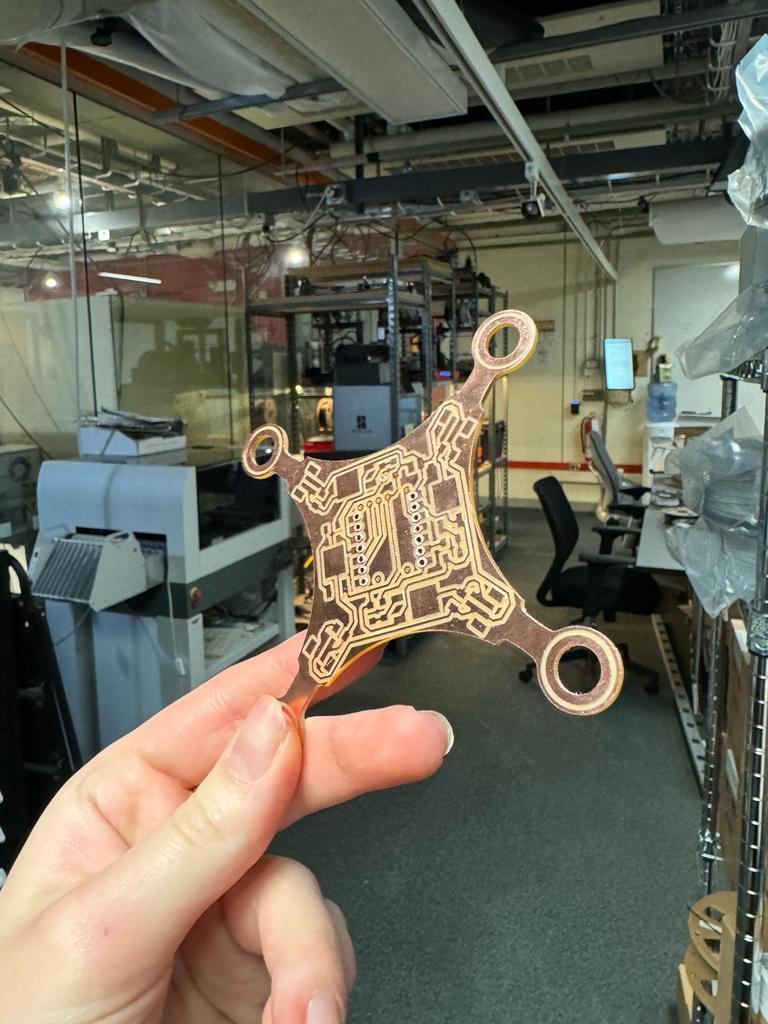
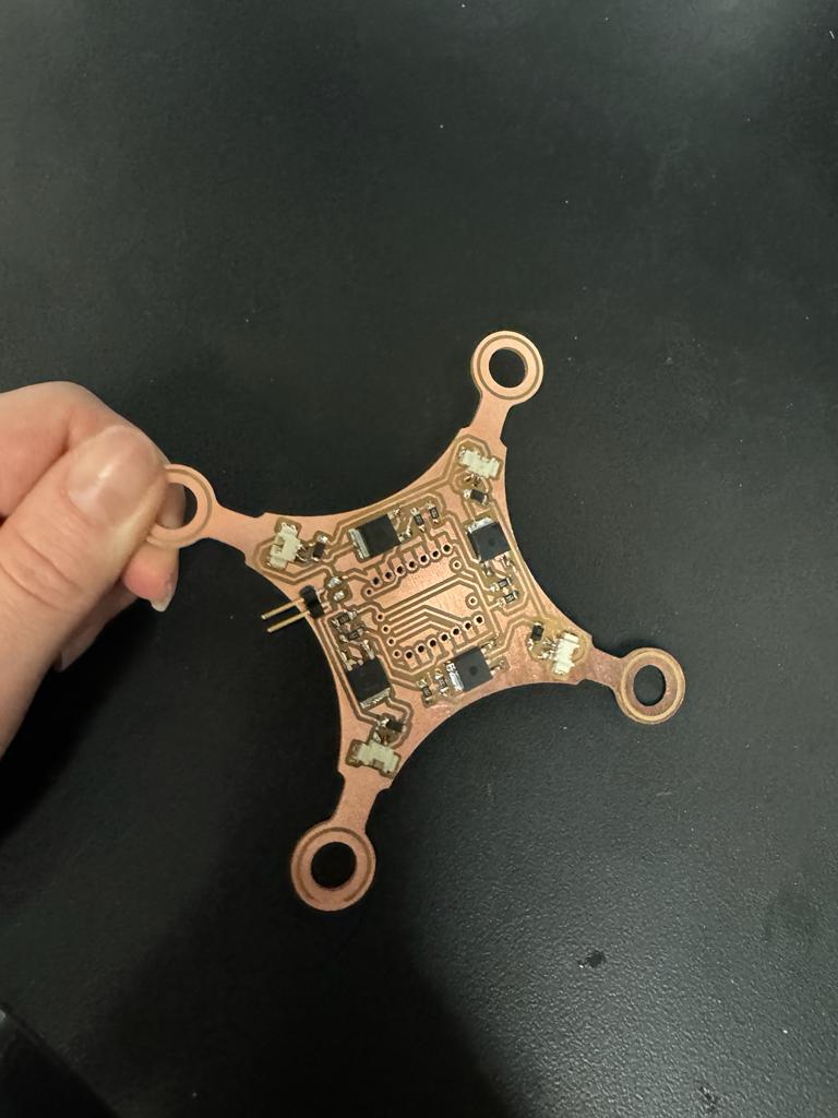
Later, in our pursuit of a lightweight design, a strategic decision was made to transform the PCB beyond its traditional role as an electronic component. Instead, we opted to leverage the PCB as an integral structural element, serving as the primary frame for the drone. Consequently, we abandoned previous considerations of constructing the frame through laser cutting materials like cardboard or plywood.
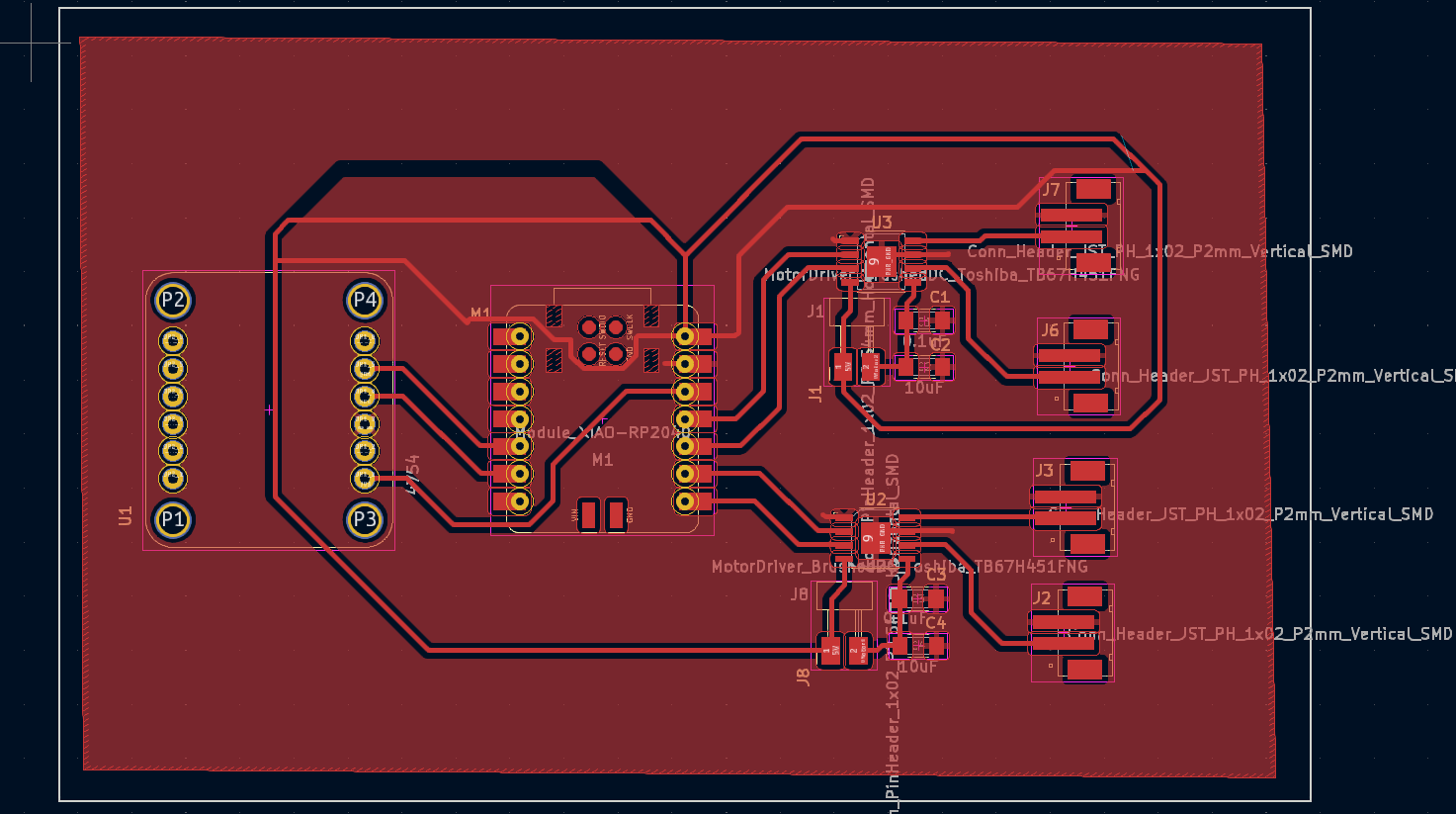
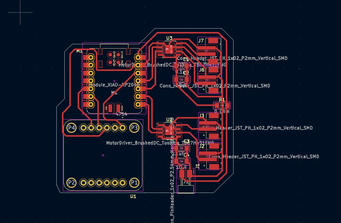
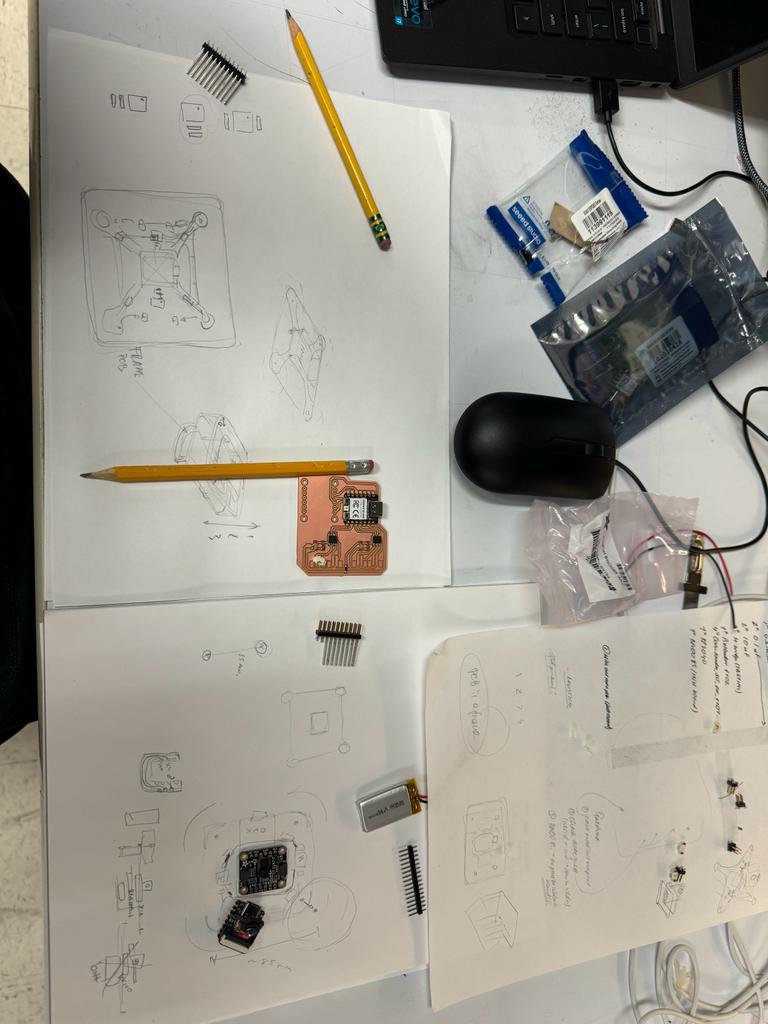
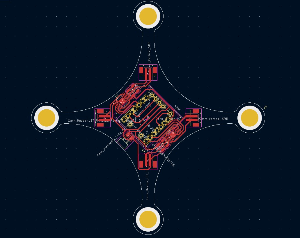
During the collaborative sketch session with Miana (see Sketch with Miana 1:1), I found myself engaged in extensive maneuvers within KiCad, a software not conventionally recognized as a proper Computer-Aided Design (CAD) tool. The intricacies of this task demanded a considerable amount of effort to navigate KiCad's functionalities.

Here is the PCB design outocme!
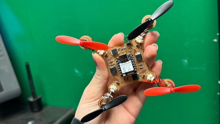
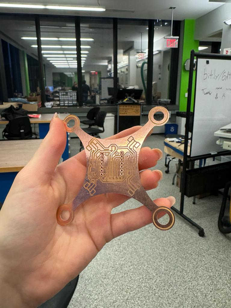
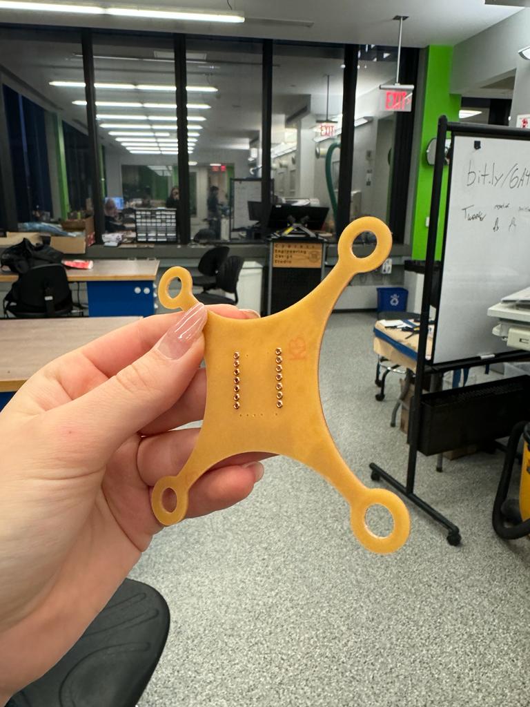
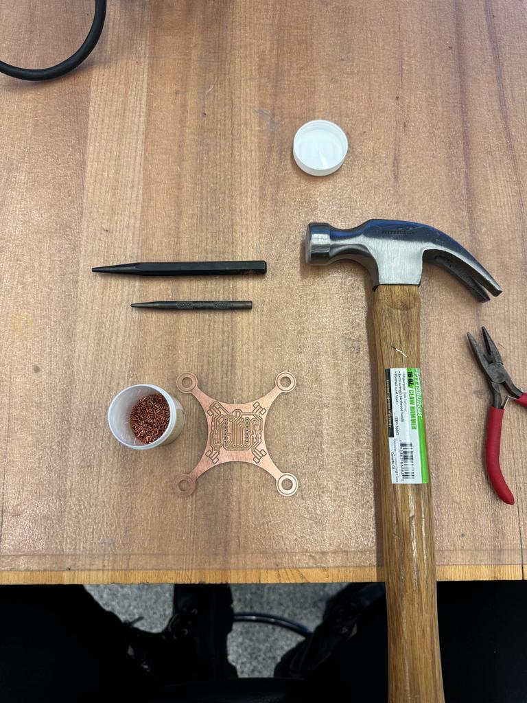
Here are some production photographs!
After soldering all parts on it, I wrote a simple code to just turn on the motors. It was a succes! All the motors nicely followed one second delay
Here is the video:
Unfortunately, when we powered the drone using a 3V power supply (as we initially opted for a lower voltage), the H-bridges experienced a malfunction, emitting smoke in the process. It became evident that they were unable to handle the current drawn by the motors. Subsequent investigation revealed that the DC brushed motors were pulling such a substantial amount of amperage that an alternative solution had to be sought. Upon conducting separate tests on the DC brushed motors, we were taken aback by their robust performance. The extent of their strength is showcased in the following video, which we encourage you to watch.
Here is the blown-up PCB board.
Part 3: Second Loop
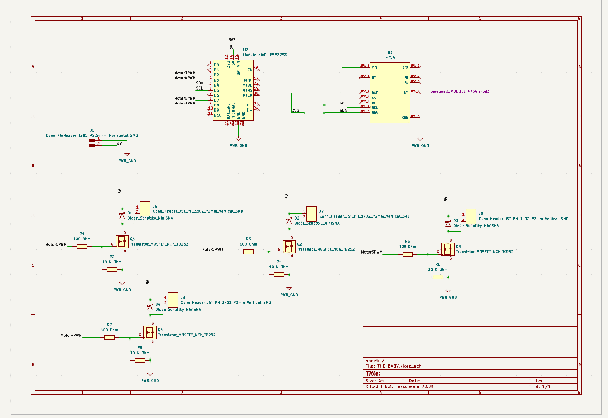
So from part 2 we have learned that the electronc design didnt work. I had to come up with another solution. After discussion the descision has been made to use mosfets (transisors) for each individual motor
The decision to employ MOSFETs (transistors) after the unfortunate incident of the H-bridges malfunctioning is grounded in their ability to address the specific challenges that arose during the initial electronic design. Unlike H-bridges, MOSFETs provide a more efficient and controlled means of managing the current flow to the motors.
MOSFETs operate as electronic switches, allowing for precise modulation of power to the motors. By using individual MOSFETs for each motor, we gain the flexibility to regulate the current independently, mitigating the risk of overloading or malfunction. This approach is particularly advantageous when dealing with DC brushed motors that demand careful current management.
Moreover, MOSFETs are known for their high-speed switching capabilities, which enables swift and accurate adjustments in motor operation. This is crucial for achieving the desired responsiveness and control in a drone application.
In summary, the shift to MOSFETs from H-bridges is a strategic response to the limitations encountered in the initial electronic design, providing a more tailored and reliable solution for controlling the motors in the drone.
Here is the new design:

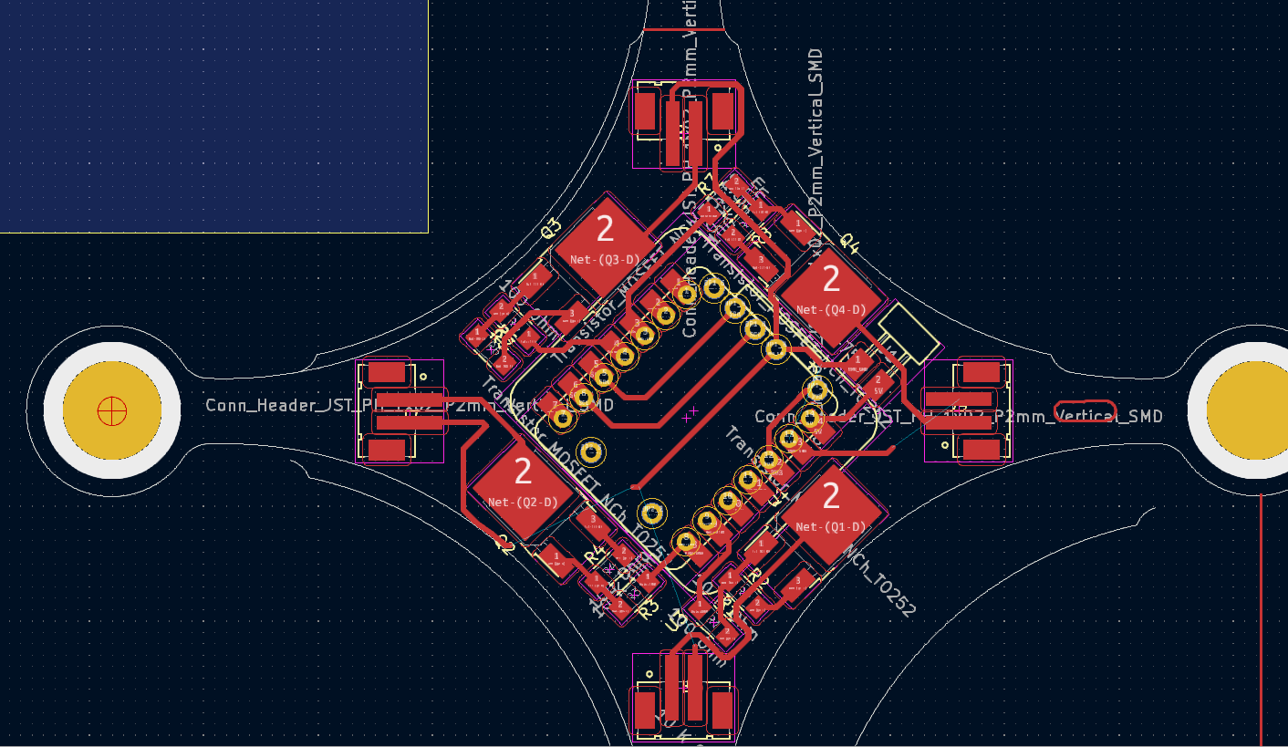
Making Process:

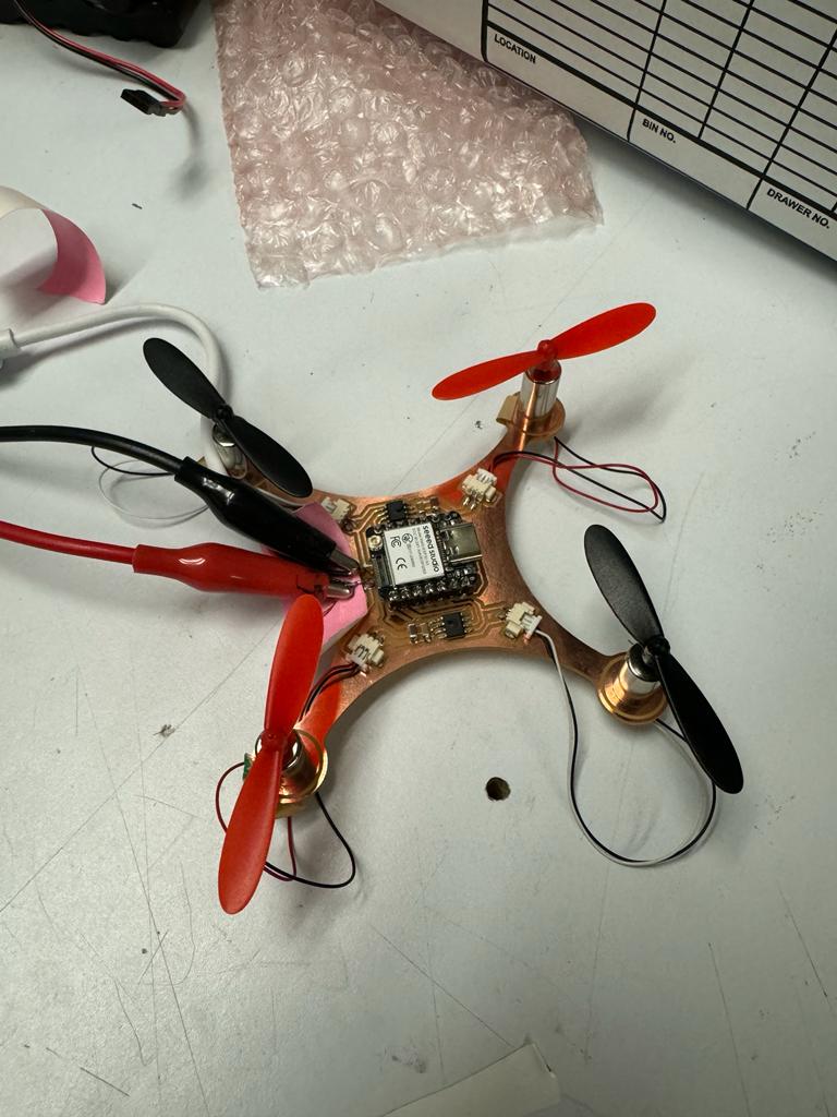
Following the soldering process and conducting initial tests with a 5V supply through my laptop, I discovered that only two motors powered on, exhibiting a behavior resembling that of "clock hands." This pattern persisted when I conducted further testing with an external power supply. It was at this juncture that I delved into the intricacies of debugging.
Following the soldering process and conducting initial tests with a 5V supply through my laptop, I discovered that only two motors powered on, exhibiting a behavior resembling that of "clock hands." This pattern persisted when I conducted further testing with an external power supply. It was at this juncture that I delved into the intricacies of debugging.