Week 6
Molding & Casting
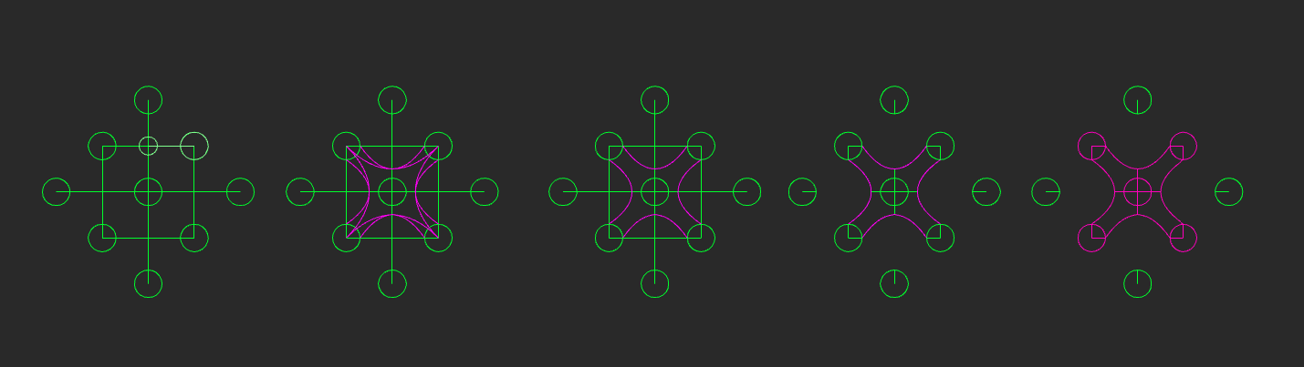
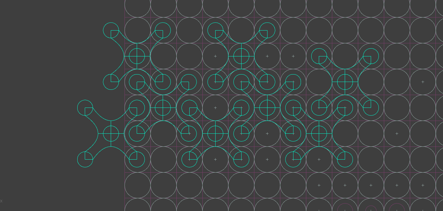
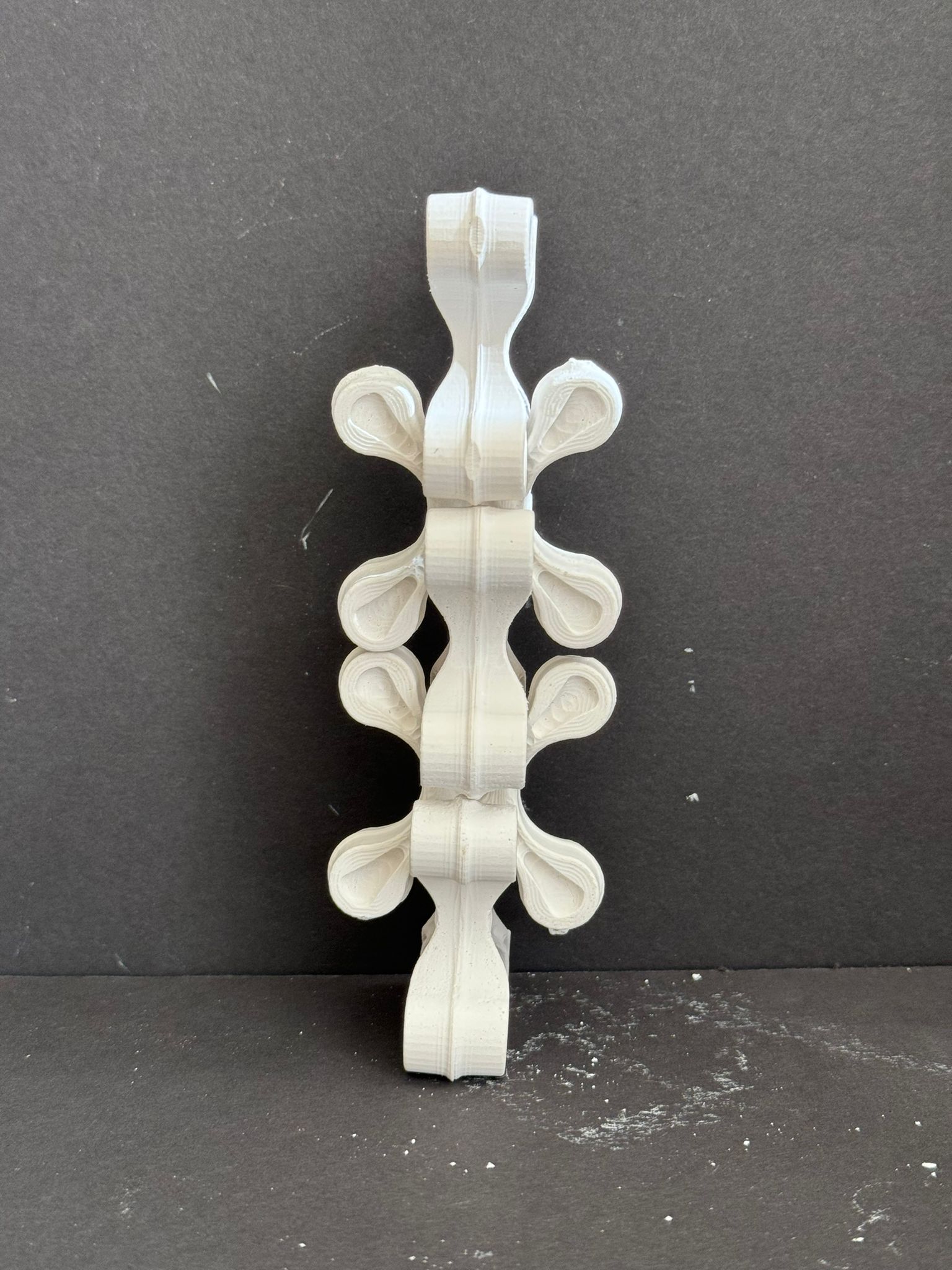
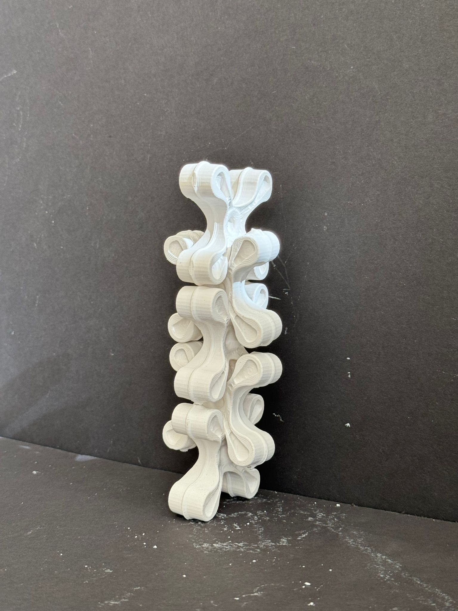
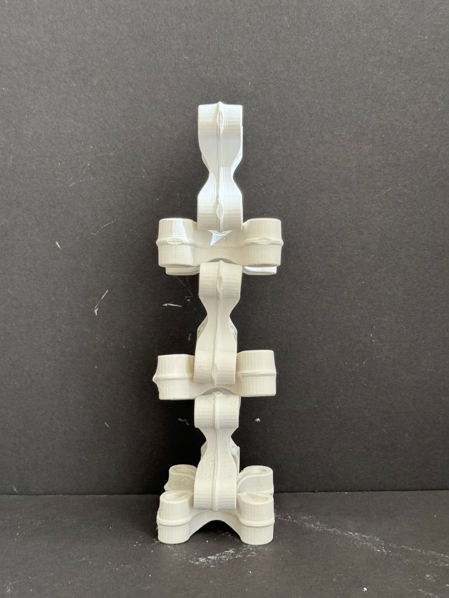
This week, I embarked on a new design challenge: creating a versatile "module" or "unit" that could be easily assembled in both plan and elevation, and replicated as many times as needed.
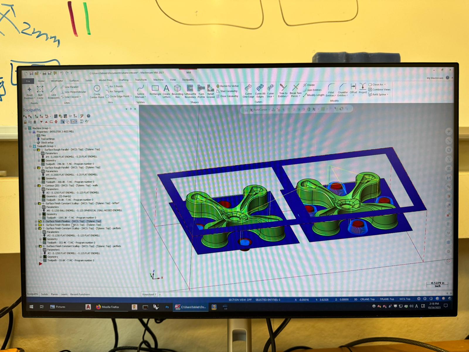
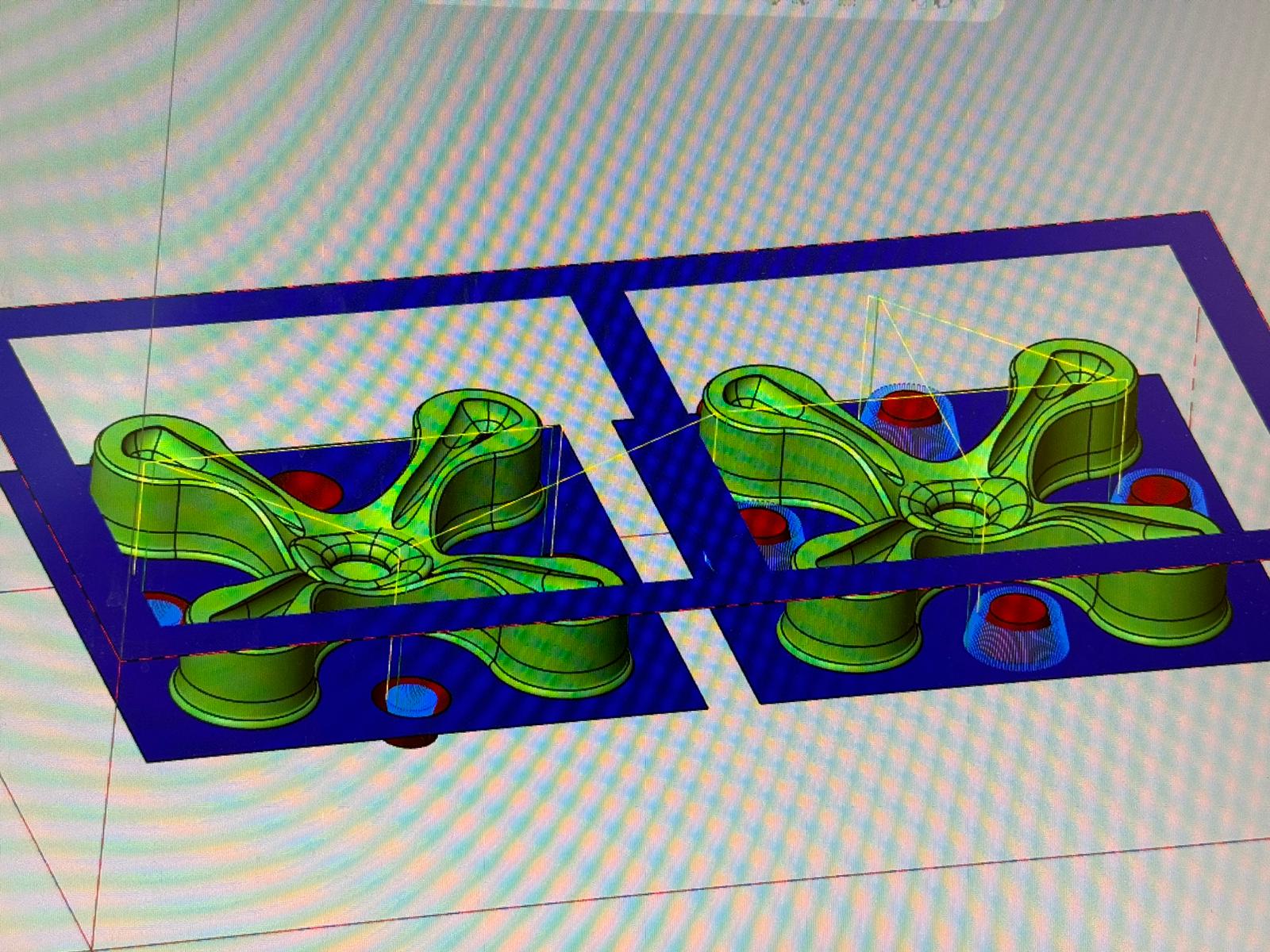
To start this creative journey, I dove into Rhino, crafting a preliminary design to test my concept for the module. It took some time to shape the idea into reality, and my peers playfully likened the design to a miniature drone due to its intricacy.
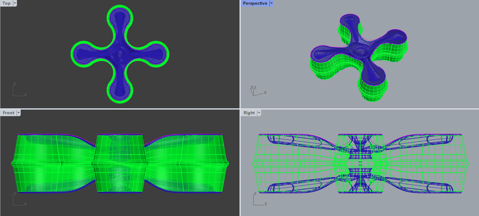

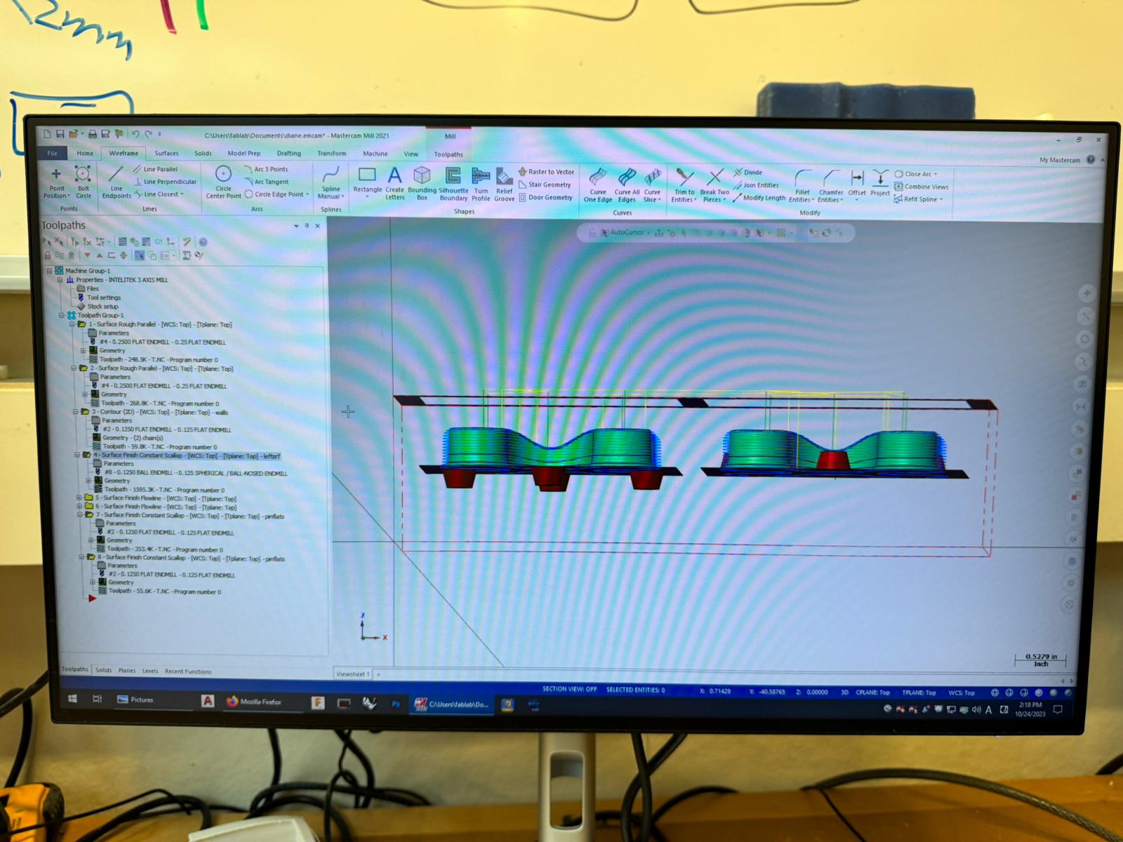
Following the digital design phase, my focus shifted to the practical side of things. I had to create a mold suitable for the CNC machine. The mold I devised was a two-part structure, carefully dividing my model with a simple 2D plane. This clever division ensured that the two halves of the silicone molds would possess flat mating surfaces, critical for a successful outcome.
In the process, I included a .125" circle, corresponding to the width of our smallest end mills on the various routers. This served as a visual guide, helping me understand how precisely an 1/8 inch tool would fit, or not fit, when cutting along the edges of an object. These toolpaths necessitate a little extra space beyond the tool's diameter for proper maneuvering, especially when dealing with intricate cuts.
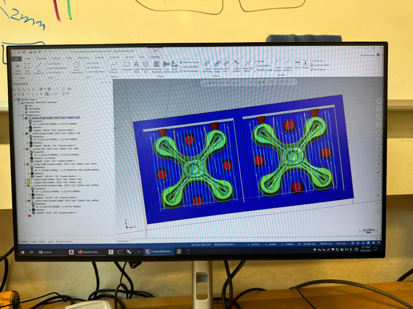
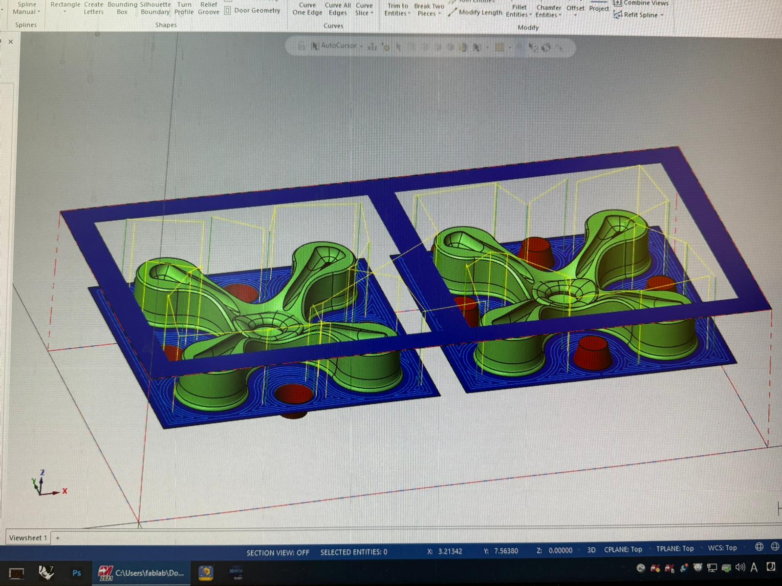
It's worth noting that I received advice not to convert my file to an STL format. Instead, I was advised to send a 3dm, step, or another NURBS model type. Meshes, as I learned, can pose more challenges when it comes to the computer-aided manufacturing (CAM) process.
Lastly, I paid careful attention to the depth of the geometry. Ensuring that it was recessed deep enough was crucial, as it would ultimately determine the thickness of the material at the bottom of the negative space once the silicone was poured. This attention to detail would play a pivotal role in the success of the molding process.


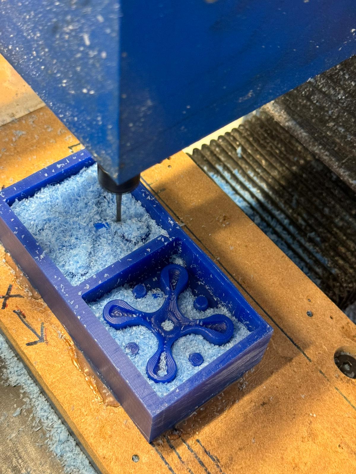
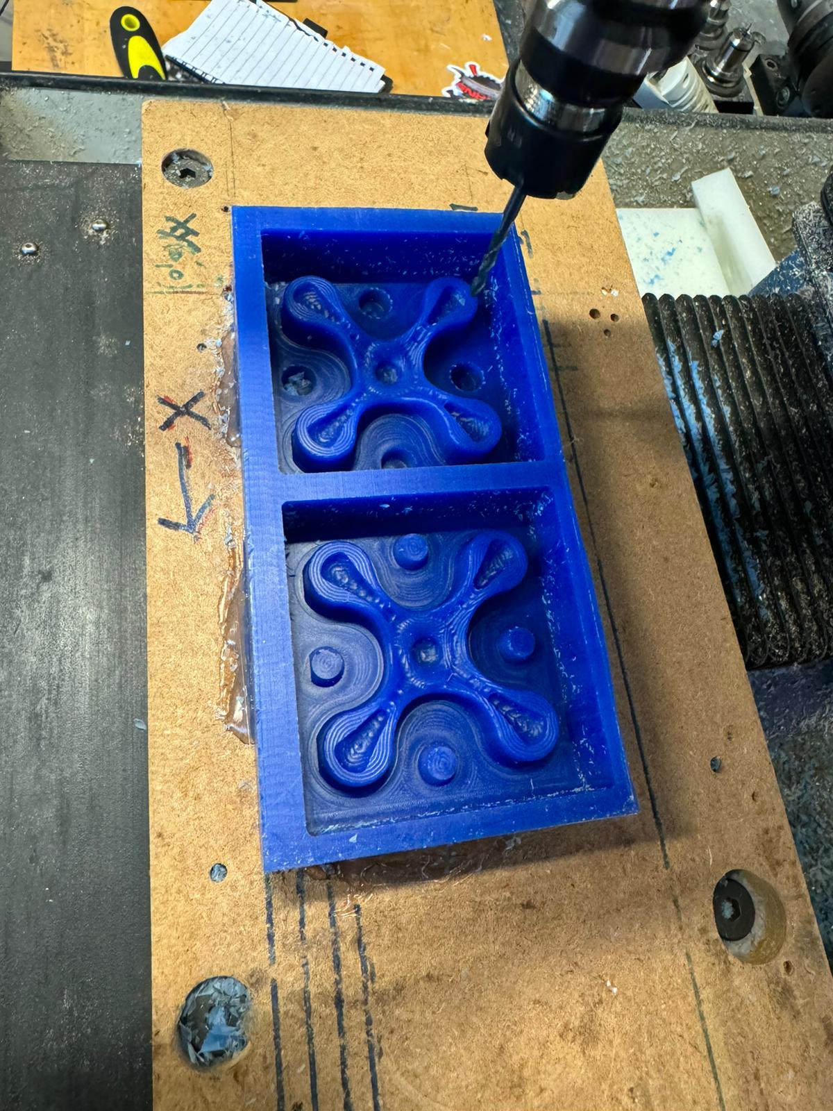
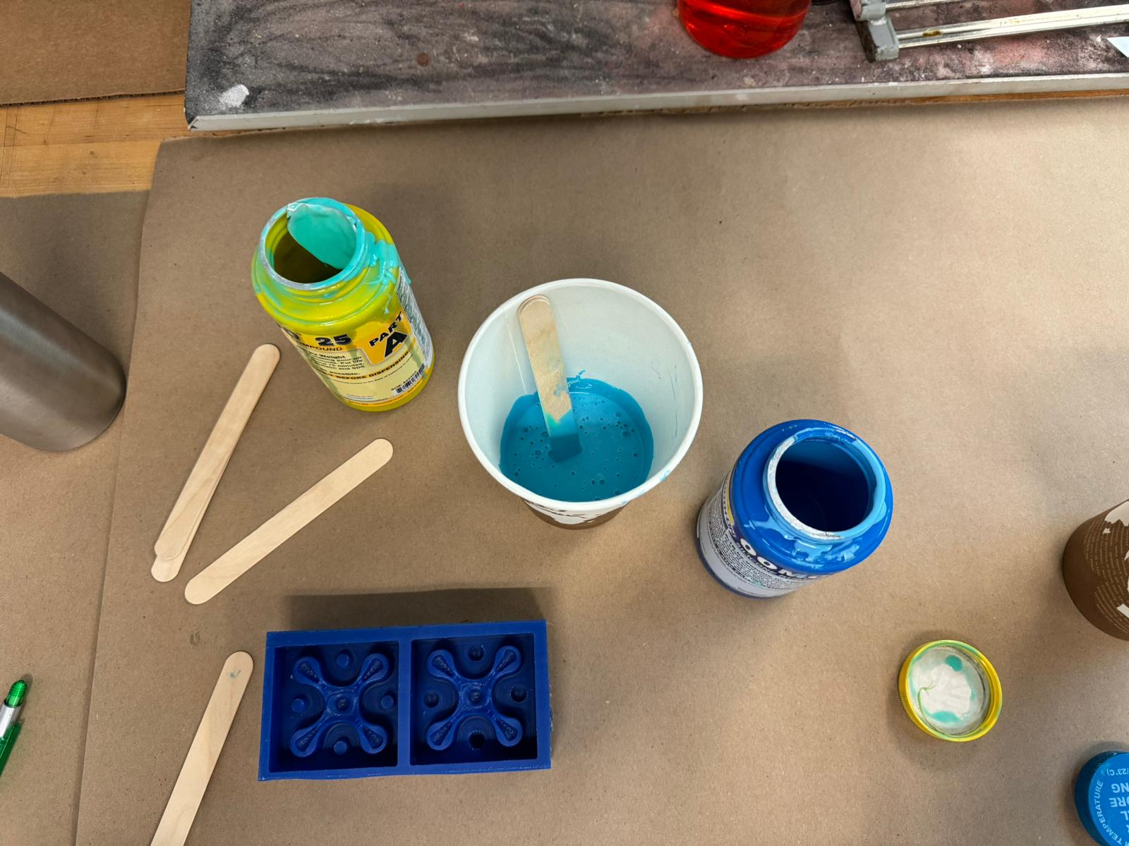
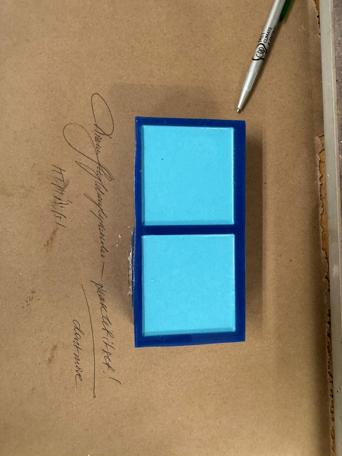

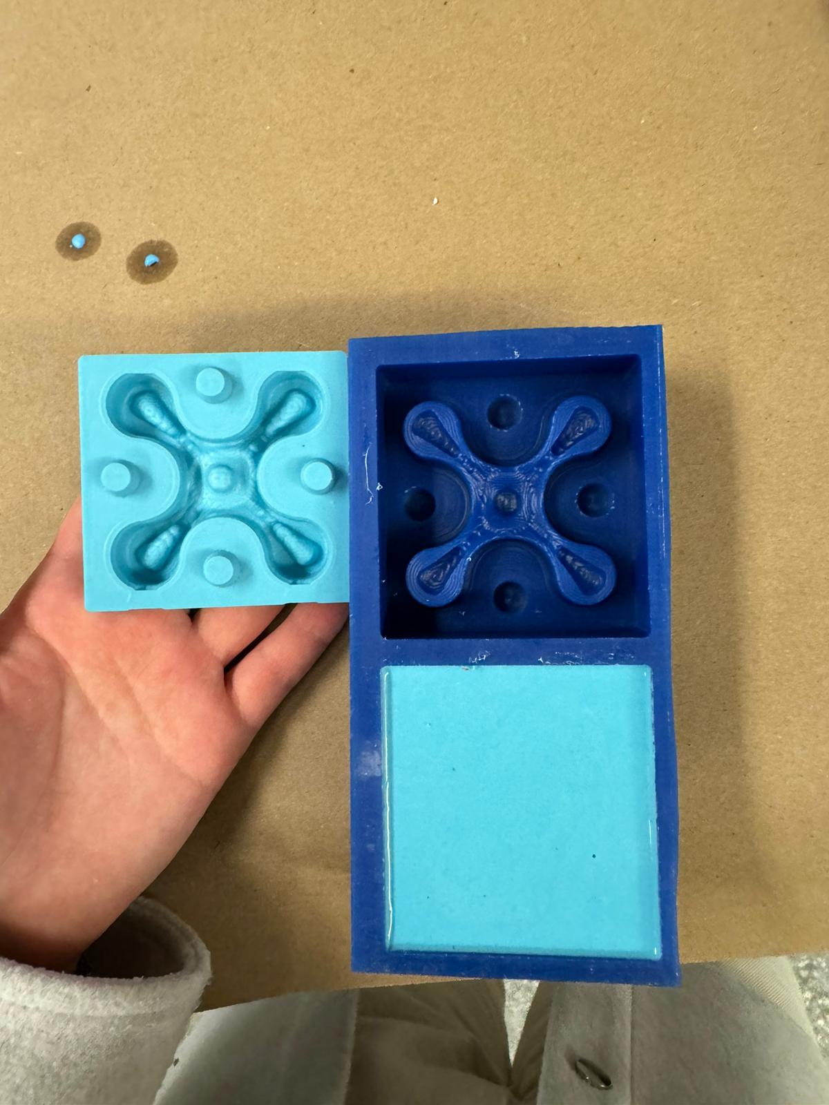

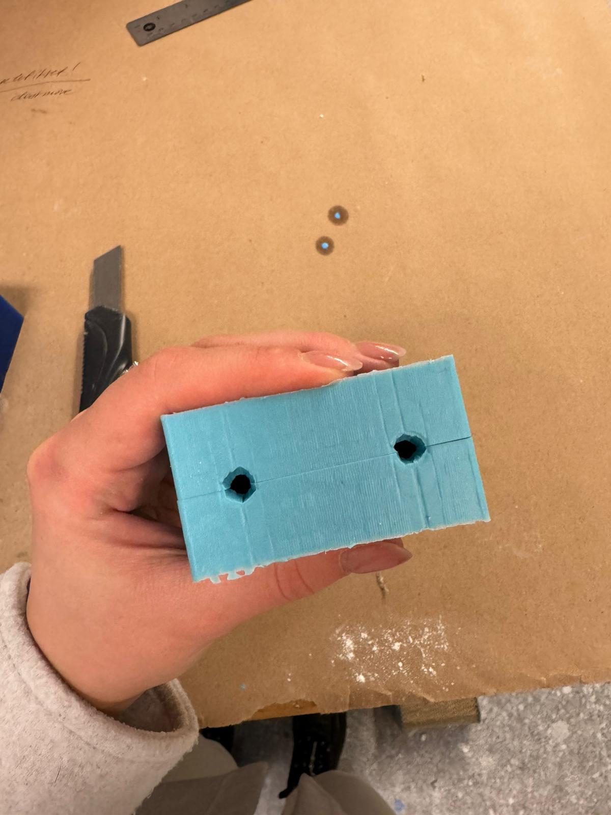

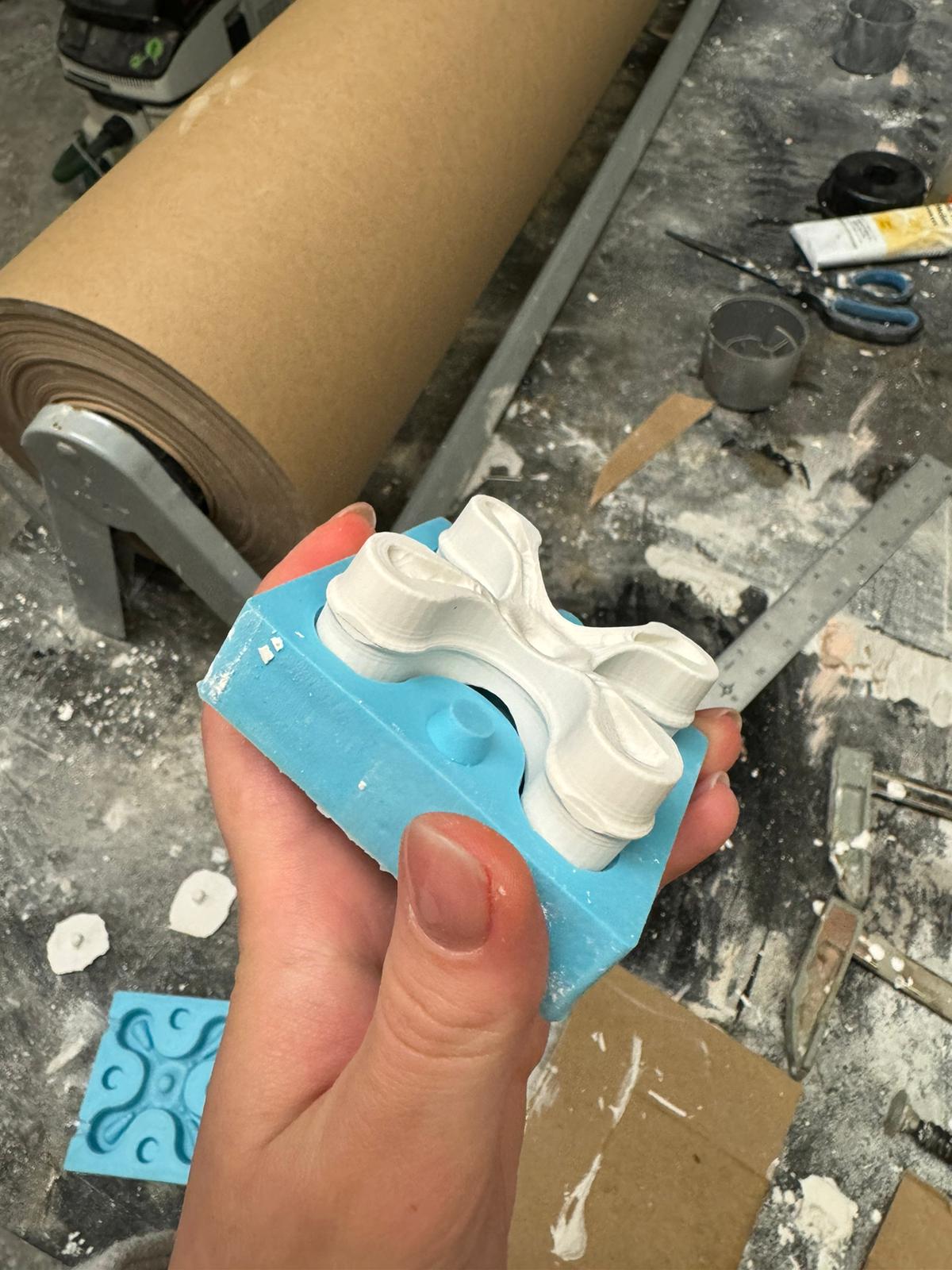
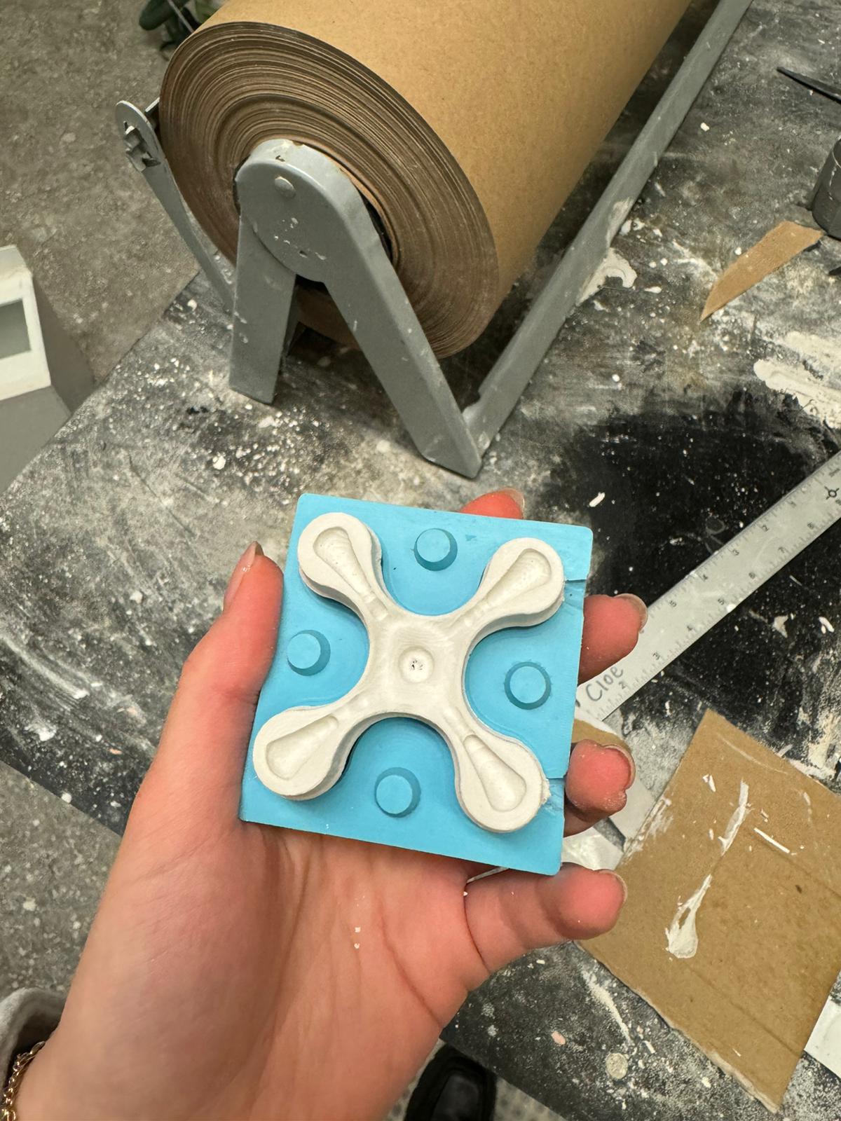
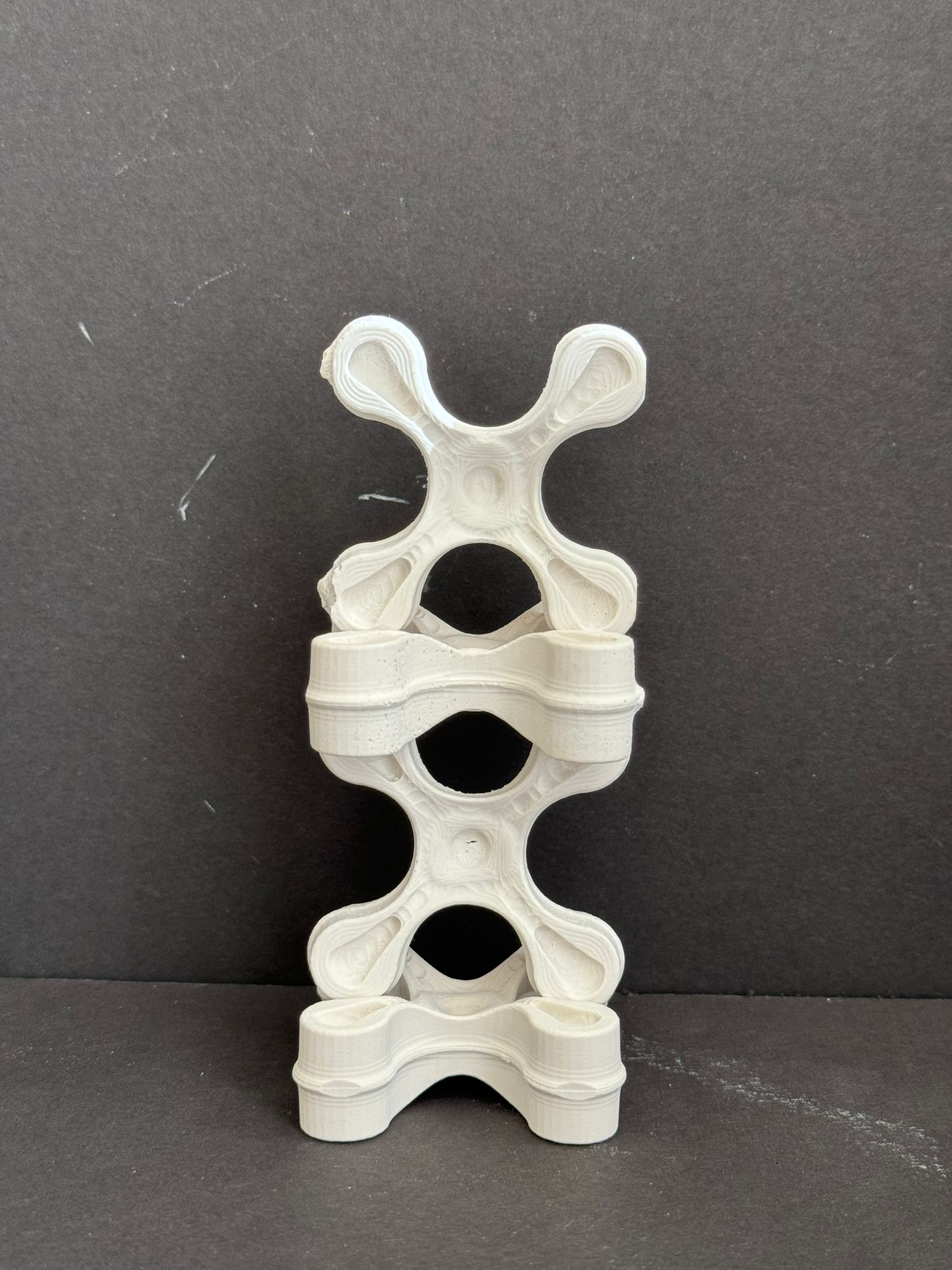
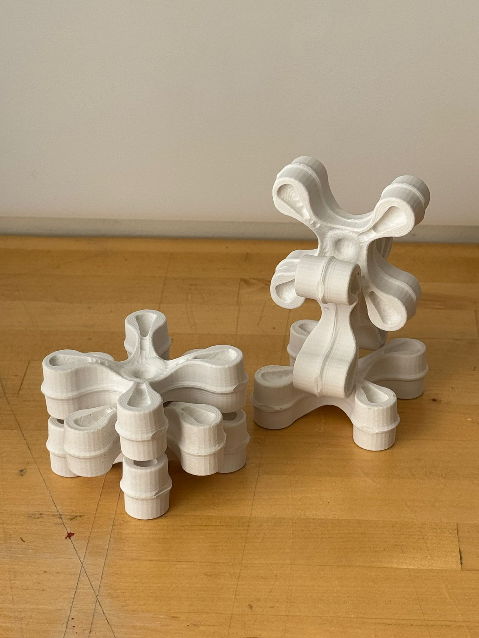
As a result of this immersive learning process, here are some quick photos of the outocme.


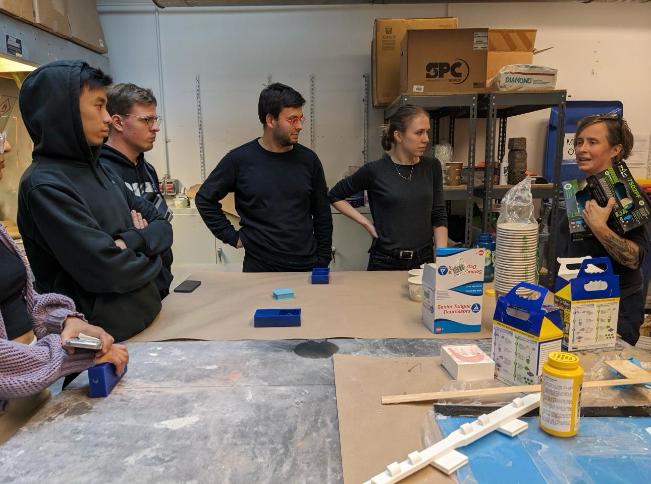
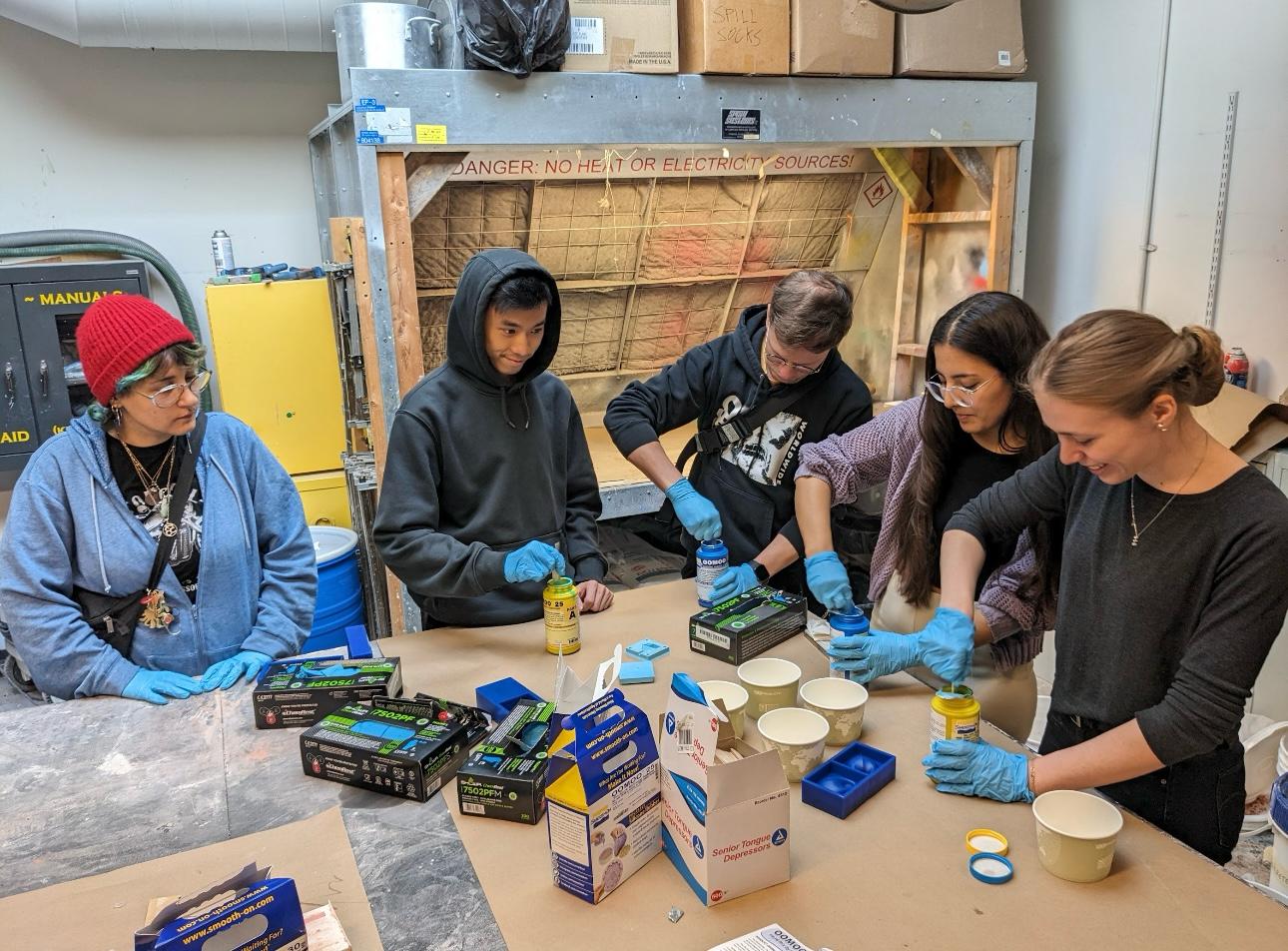
Group Project
It was fun .. more description to follow.