WEEK 4 : Electronic Design
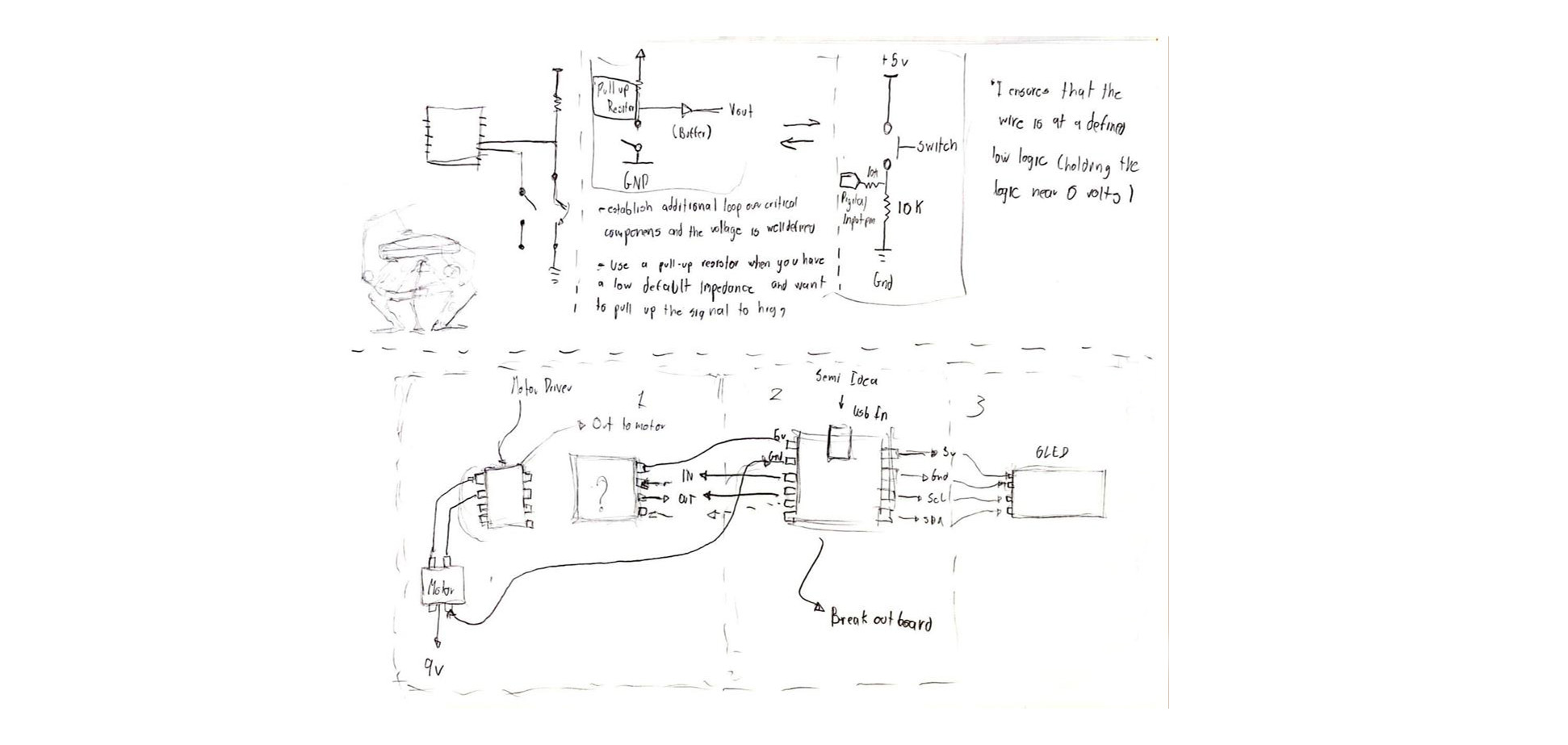
For this weeks assignment I want to treat it a little bit different since I want to list some of the resources that helped me during this week as I go through the process of designing my first ever PCB board. Sooo starting with KICAD after the recitation it was clear it was KICAD felt the most intuitive software for me. I also started browsing through some of the previous websites and ran into my old friend's Kim from 2021, where he links this video from Zack their Ta where he goes step by step on how to load the libraries on KICAD and get started. Then I also did some research onto pull up and pull down resistors here and finally I started sketching a bit what I thought my board could do for the final Project break out onto OLED and a motor
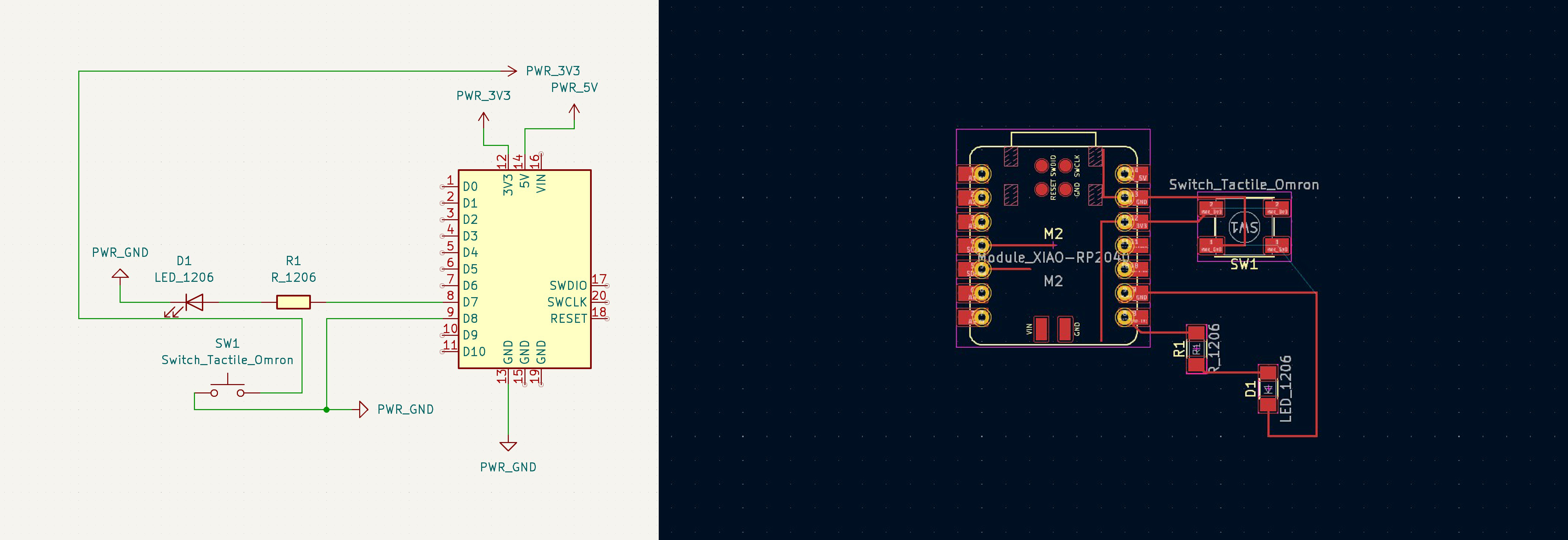
So first I started playing with KICAD and getting familiarized with the tool I started by making a pretty simple board, just added a LED and a switch, the recitation for last week really helped me getting started
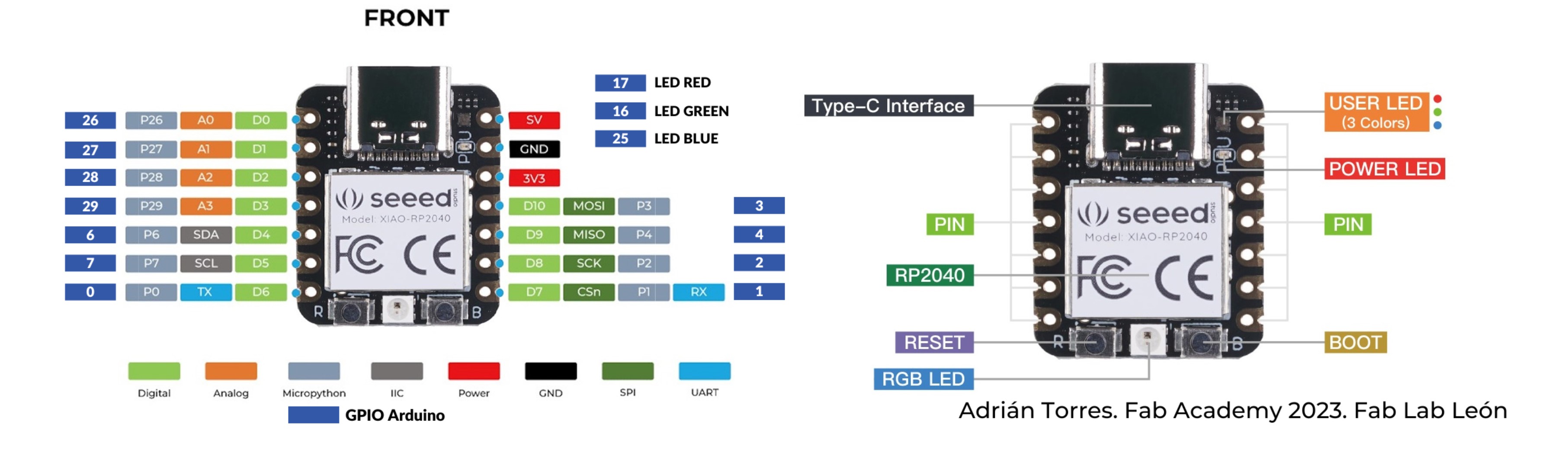
Then I again went back to the Board's data sheet after hearing Anthony in the recitation say "all pins are not created equally" in order to understand the difference in-between pins and not make any dumb moves like block the RX or TX ones when starting to create the breakout board, I also did some research on the difference between digital and analog pins and found this link helpful.
Then I slowly starting adding more components to the board in order to give it more ins and outs pins to hopefully be able to connect a stepper motor and connect the LED's

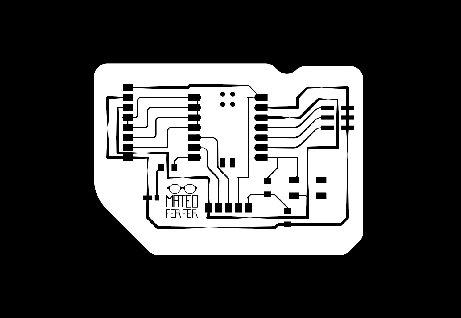
This is the first output SVG I made from KICAD, (still working on some issues on determining the thickness of the wires and spacing) also unsure if my conn_pinheader needs to be connected to power and ground or if it can just work as inputs and outputs
Then I found this lifesaving link from one of the CBAS instructors, and tried to follow what he did as it seems the break out board he created would be perfect for what I intend to create with my final project, I started by adding the elements that I need from the library and going back and forward from the pcb editor and the schematic.

Then I tried to complete the wiring to have more inputs and outputs so I can hopefully connect LEDs from one side and a motor from the other for my final project.

Customized!
Then I tried to visualize it on the 3d but only one of the components appeared I dont know why I shall figure it out for next week!

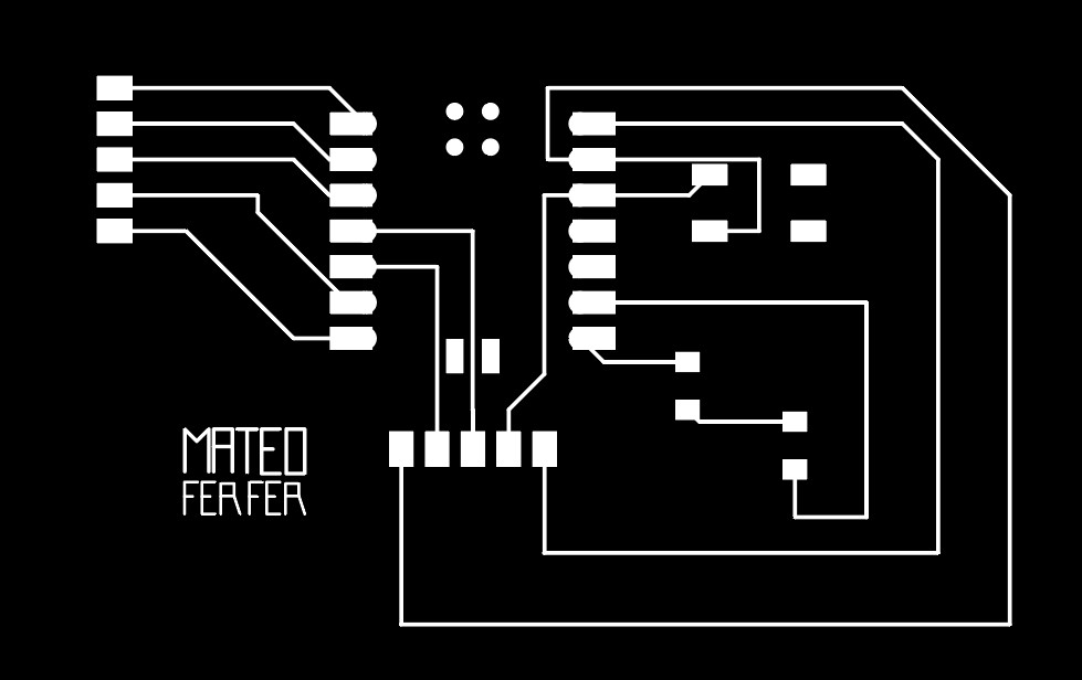
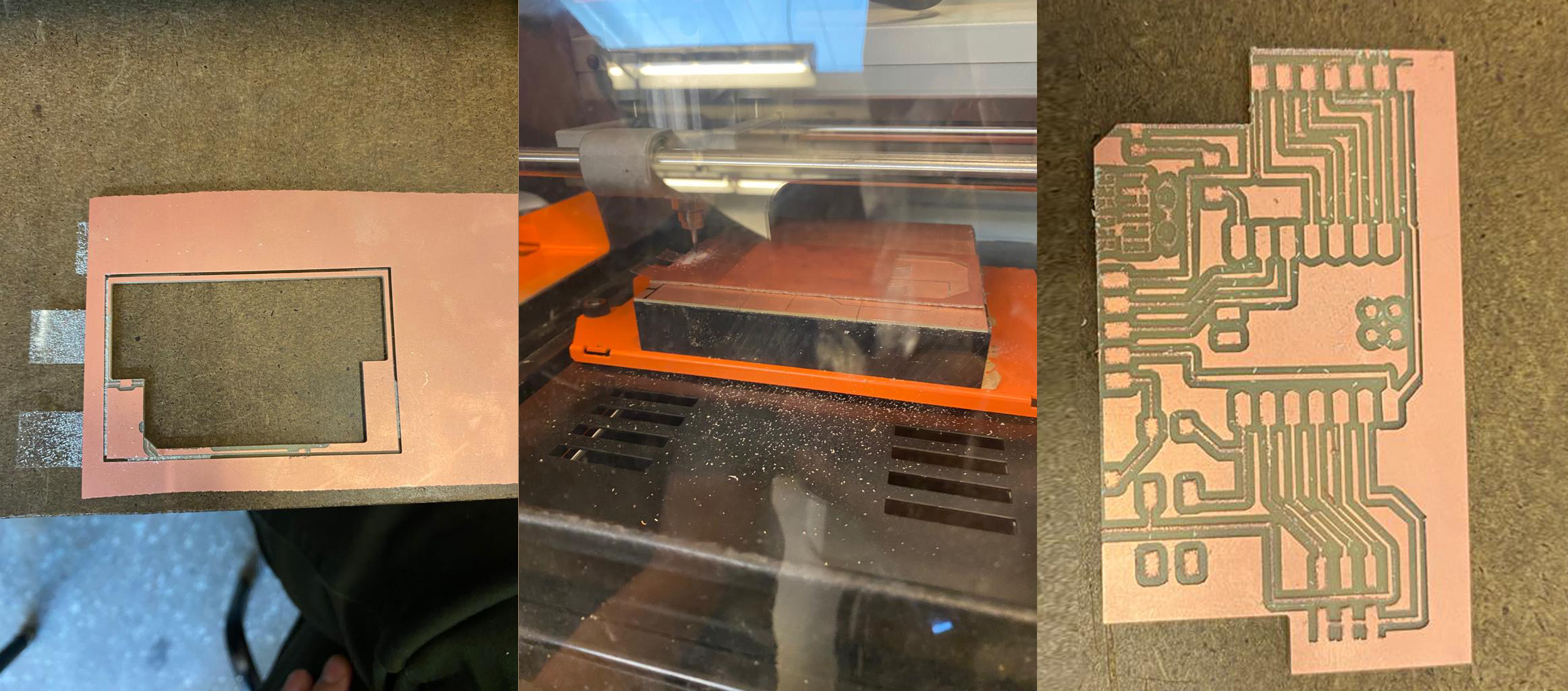
I tried to mill it but messed up, the wires were too thin and I chopped some of the board I dont know why but I will figure it out for next week
.jpeg)