I started my week to actually researching through videos, data sheets, previous examples. I realized that making a speaker and taking out a smooth audio is a very complex job. Therefore after researching like 2 days, These are the main idea of the amplification process. After a really short introduction to the idea, I will continue with further application details.
To play sound using a microcontroller like the Xiao RP2040, which uses PWM (Pulse Width Modulation) for producing analog-like signals, you need to generate audio signals and interface them correctly with an audio amplifier. First, use the PWM pins of the microcontroller to create the audio signals. This involves coding to modulate the PWM duty cycle, creating audio waveforms that can range from simple tones to complex audio, depending on the microcontroller's capabilities and memory.
However, the PWM signal is too 'rough' for direct audio use and needs to be smoothed out. This is where a low-pass filter comes in. By using a resistor and a capacitor, you can build an RC (Resistor-Capacitor) filter. This filter allows low-frequency audio signals to pass through while blocking the high-frequency PWM components, creating a smoother analog signal. The cutoff frequency of this filter should be set higher than the maximum audio frequency you want to play but lower than the PWM frequency, typically around 20 kHz for audio applications.Finally, after filtering, the signal is ready to be fed into the audio amplifier. For added control, a potentiometer can be inserted between the filter and the amplifier to adjust the volume.
Here are the links that helped me to understand the audio amplification; Audio Amplifier Basics , LM386 Audio Amplifier with Bass Boost, How does an Amplifier Work? (Class-A), LM4871 Boomer Data Sheet.
Building Speaker as a output device, Logic of amplification
With Antony's suggestion, I decided to use LM4871 audio amplifier that is included in archshops inventory. The LM4871 is an integrated audio amplifier designed for compact, portable devices. It operates efficiently in a bridge-tied load (BTL) configuration, allowing it to deliver a higher power output to a speaker without requiring a dual supply voltage. This makes it ideal for single-voltage, battery-powered applications like mobile phones or portable speakers. The LM4871 stands out for its ability to work effectively at low voltages (around 2.0V to 5.5V) and its minimal need for external components.
When creating a circuit with the LM4871, I needed to connect a power source (microcontroller) 3.3 volt, a speaker, and a few capacitors and resistors for filtering and stability. I also added a tactile slider for the shutdown feature.

PCB Design, Components
For the design I utilised the data sheet of the amplifier, only added one swich to be able to shut down the sound when needed. You can see the diagram below which is shared in data sheet.

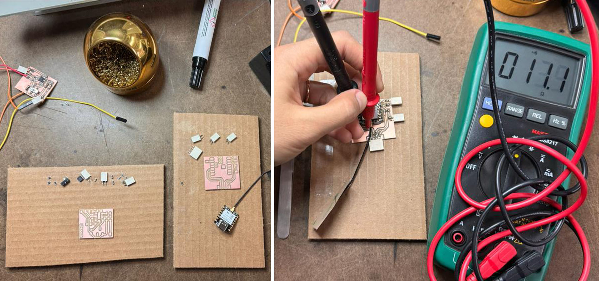
IMPORTANT! The initial PNG file I uploaded to the milling machine was somewhat unclear, leading to a poor-quality outcome. The details were overly smooth and inaccurately represented, as evident in the right-hand image. The top image showcases the issue with the blurry PNG, where intricate features like the LM4871 traces merged together. I created my document using Illustrator. Although the document is a vector file, it's crucial to navigate to the 'effects' section before exporting and select 'rasterize', setting the resolution at 300 dpi. The default setting is often 72 dpi, which can cause the PNGs to be pixelated and the final output to appear blurred.

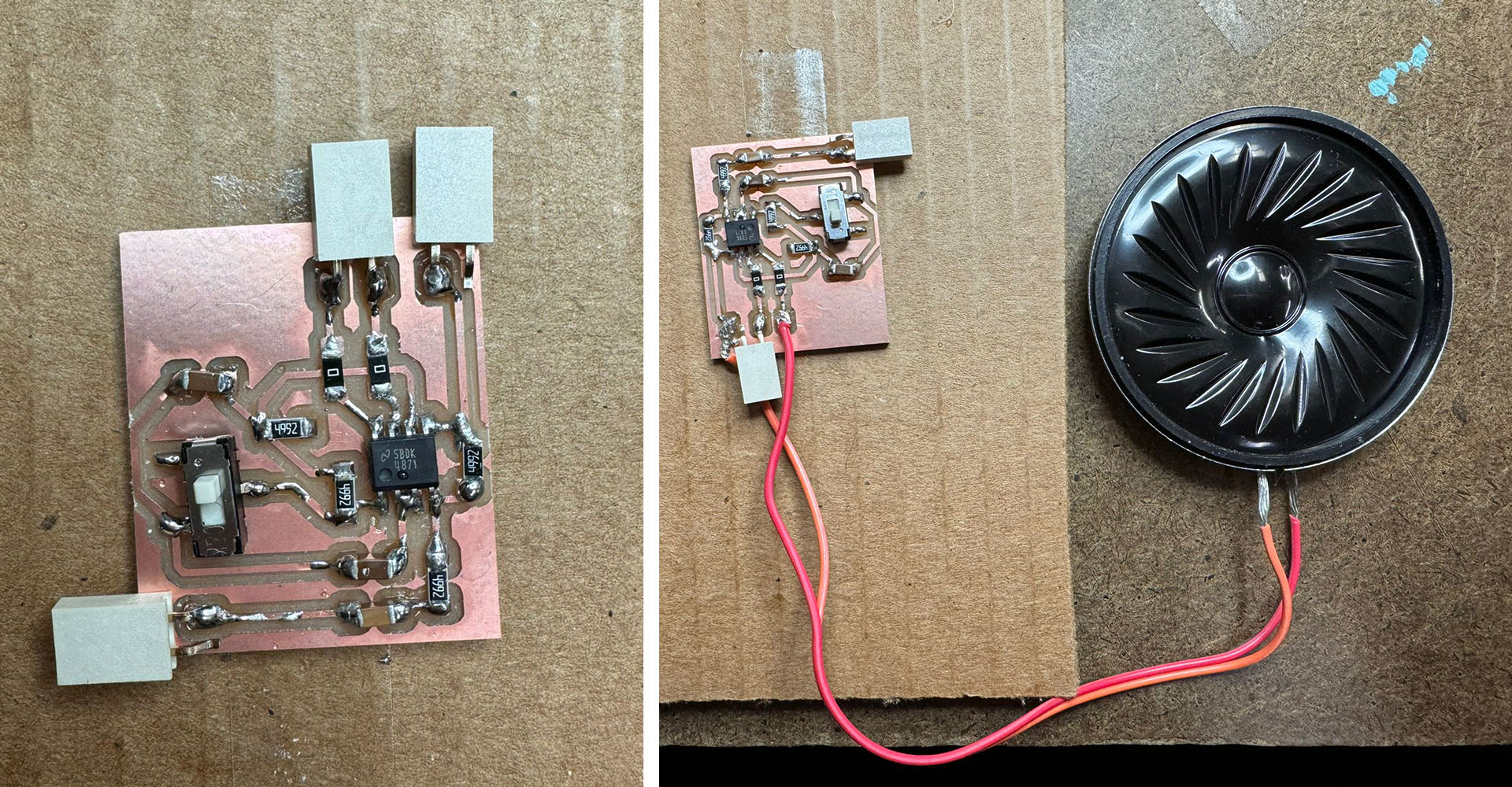
In the archshops I could not find the exact values for resistors and capacitors. Therefore I used three 49 ohm resistors and 2x1.O UF and one 0.1 UF capacitors. This was the closest values I can get.
Results, Outcomes
So I tried to upload a buzzer code to see if my circuit is working. However, it did not work. Here is the basic code I used.
While designing the circuit in KiCad, I named the ground and power of the audio amplifier separately to connect it to the microcontroller and showed it as an external pin. That's why the ground and power amplifier circuit were not completed. This very simple error caused the system to stop working. So I rebuilt it from scratch.
Fixing the errors, new circuit
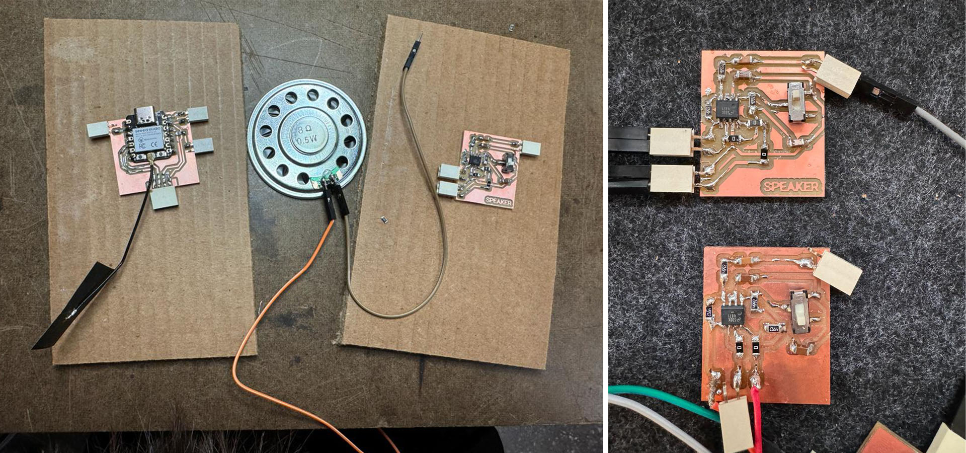
This time, after combining the ground and power of the entire system, I added a connecting power outside the ground and power. You can find the new LM4871 audio amplifier circuit below.

Every time I solder and mill, the process becomes more straightforward. This time, I completed my task very quickly.

You can find the non-working circuit I made before and the new one below on the right.

Results
I used two different codes to test the circuit. One for using the speaker as a buzzer and the other for beeping. Below you can find both codes and videos of the results of these codes.
const int buzzerPin = 3; // Define the buzzer pin

void setup() {
  // Initialize the buzzer pin as an output
  pinMode(buzzerPin, OUTPUT);
}

// Loop function runs over and over again forever
void loop() {
  // Turn the buzzer on
  digitalWrite(buzzerPin, HIGH);
  // Keep it on for 500 milliseconds (0.5 seconds)
  delay(500);
  // Turn the buzzer off
  digitalWrite(buzzerPin, LOW);
  // Wait for 500 milliseconds
  delay(500);
}
#include

// Define the speaker pin
const int speakerPin = 3; // GPIO3

// Define a melody
const int melody[] = {
  262, 294, 330, 349, 392, 440, 494, 523  // frequencies for notes C, D, E, F, G, A, B, C
};

const int noteDurations[] = {
  4, 4, 4, 4, 4, 4, 4, 4  // play each note for a quarter note (1/4)
};

void setup() {
  // Initialize the speaker pin as an output
  pinMode(speakerPin, OUTPUT);
}

void loop() {
  for (int thisNote = 0; thisNote < 8; thisNote++) {
    // Calculate the note duration
    int noteDuration = 1000 / noteDurations[thisNote];
    tone(speakerPin, melody[thisNote], noteDuration);

    // To distinguish the notes, set a minimum time between them.
    // The note's duration + 30% seems to work well:
    int pauseBetweenNotes = noteDuration * 1.30;
    delay(pauseBetweenNotes);

    // Stop the tone playing:
    noTone(speakerPin);
  }

  // Wait for a bit before replaying the melody
  delay(1000);
}
Both codes worked successfully. However, if I make an audio amplifier again, I will definitely add a potentiometer to increase or decrease the sound. The speaker volume is uncomfortably loud.
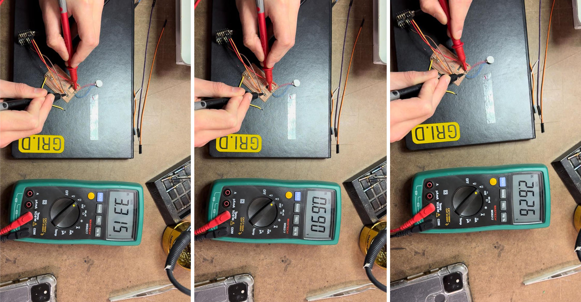
Group Work
For our group project, Danny and I worked on assessing the power needs of the buzzer circuit. Initially, we hooked it up to the 3.3V and 5V outputs of the Xiao ESP32-C3 and took measurements using a multimeter. Interestingly, even as the circuit's voltage rose, the readings for both buzzers remained relatively consistent at 0.690 and 0.697. We observed that higher voltages led to an increase in the buzzer's operating speed. Following this, we experimented with even higher voltages using a power booster and noted the corresponding changes in the buzzer's speed.