
I am incredibly excited about the opportunity to learn the laser-induced graphene technique, a fascinating process that turns out to be surprisingly accessible thanks to the widespread availability of laser cutters in many maker spaces. The simplicity of creating graphene using this method is a game changer for me. It frees me to explore and experiment with various designs, particularly in the realm of sensor technology. This freedom to design and test any kind of sensor not only fuels my creativity but also offers a practical pathway to innovation. The thought of harnessing this technique to bring my ideas to life is truly exhilarating and I can't wait to dive into the endless possibilities it presents. But of coruse, after final project... For this week, I will try to make a pressure sensor with it.
First Meeting, Introduction
On Friday, we had a productive meeting with Wedyan to discuss the laser-induced graphene technique. She provided a comprehensive overview of the materials, along with detailed instructions on machine settings and operation. Wedyan has experimented with various machines from CBA, arch shops, and EECS, fine-tuning settings for each. This groundwork is incredibly helpful, particularly for my work in the arch shops.
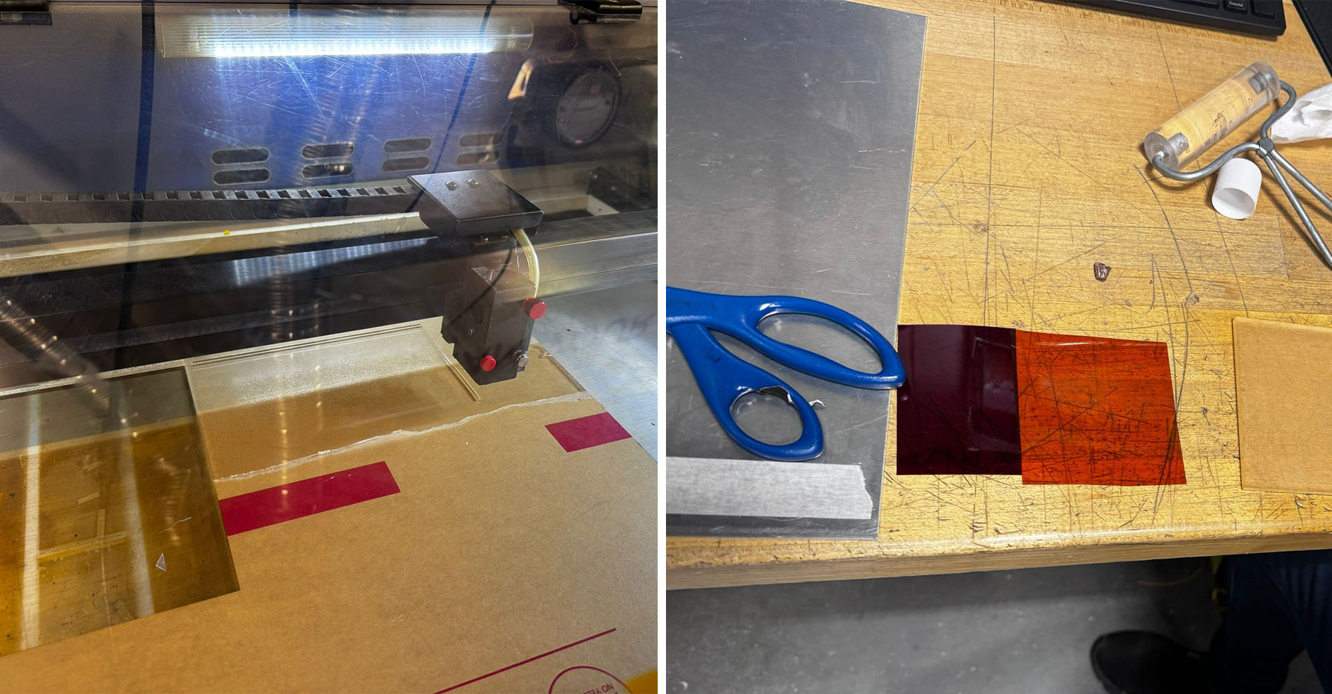
A key tip she shared was about preparing the machine: lower the bed, remove the metal grid to ensure the material lays flat, essential for avoiding burns on the polyamide. She advised using a straight aluminum plate, securing the material with tape for uniformity. This step is crucial since even minor bumps can cause burning.
For the laser setup, she recommended placing the plate on the flattest part of the machine, adjusting the focus, and then raising the bed to align with the machine's focal point. Before executing the main design, she sends a thin square outline around it, without closing the machine's door. This allows for precise positioning of the plate. Finally, she uses specific settings for the design: 1500 DPI, 1500 PPI, 8% Power, and 10% Speed. Wedyan's insights and recommendations are invaluable for navigating this process efficiently and safely.


Application
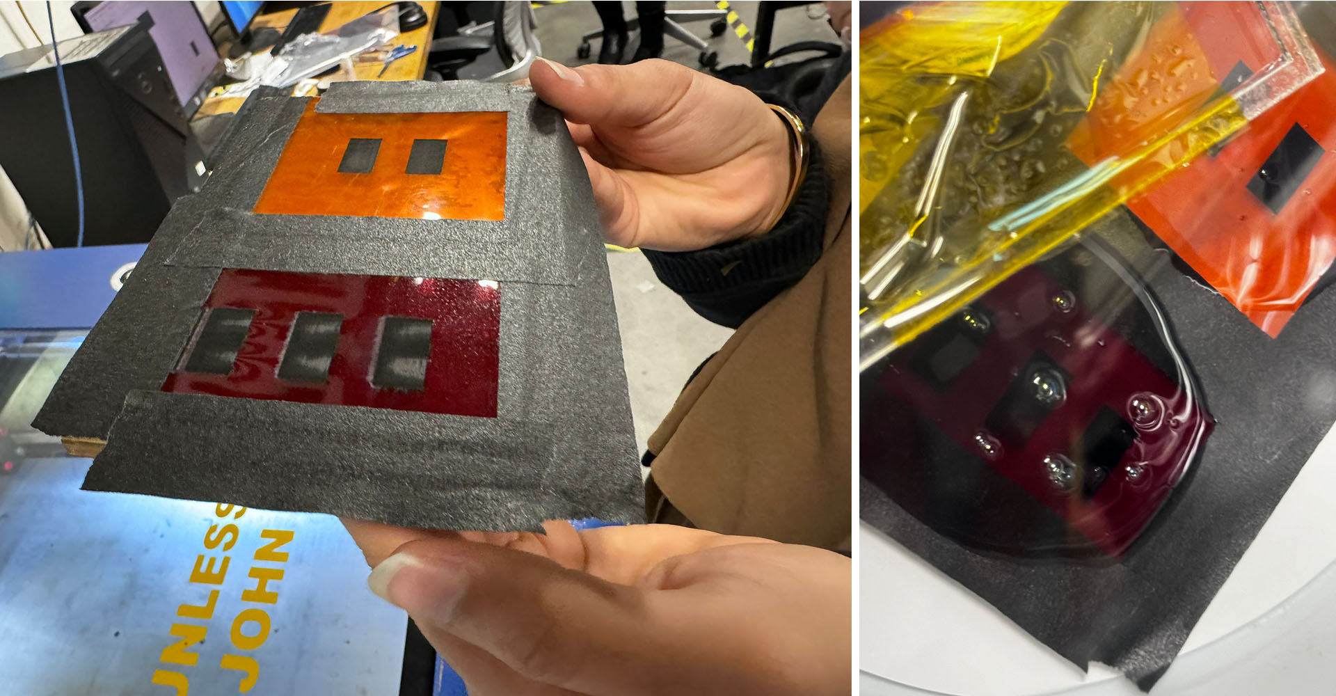
Before going to our second meeting, I told Wedyan that I wanted to make a pressure sensor, and she said she could meet with me to discuss this topic. I learned that Rachelle from our team is also interested in making a pressure sensor. We planned to use the same design to create two pressure sensors with polyamide of different thicknesses and measure their values. For the thicker one, we set the power to 30% and the speed to 40%. For the thinner one, which we had tried previously, we reduced the speed to 20%. The aim was to make it more fleaky than usual because a pressure sensor needs to have a compressible material with a resistor graphene in between. Producing more fleaky graphene will make it easier to transfer it onto PDMS later. This way, we can observe more significant changes in the resistivity of the graphene sandwiched within the compressible silicone.


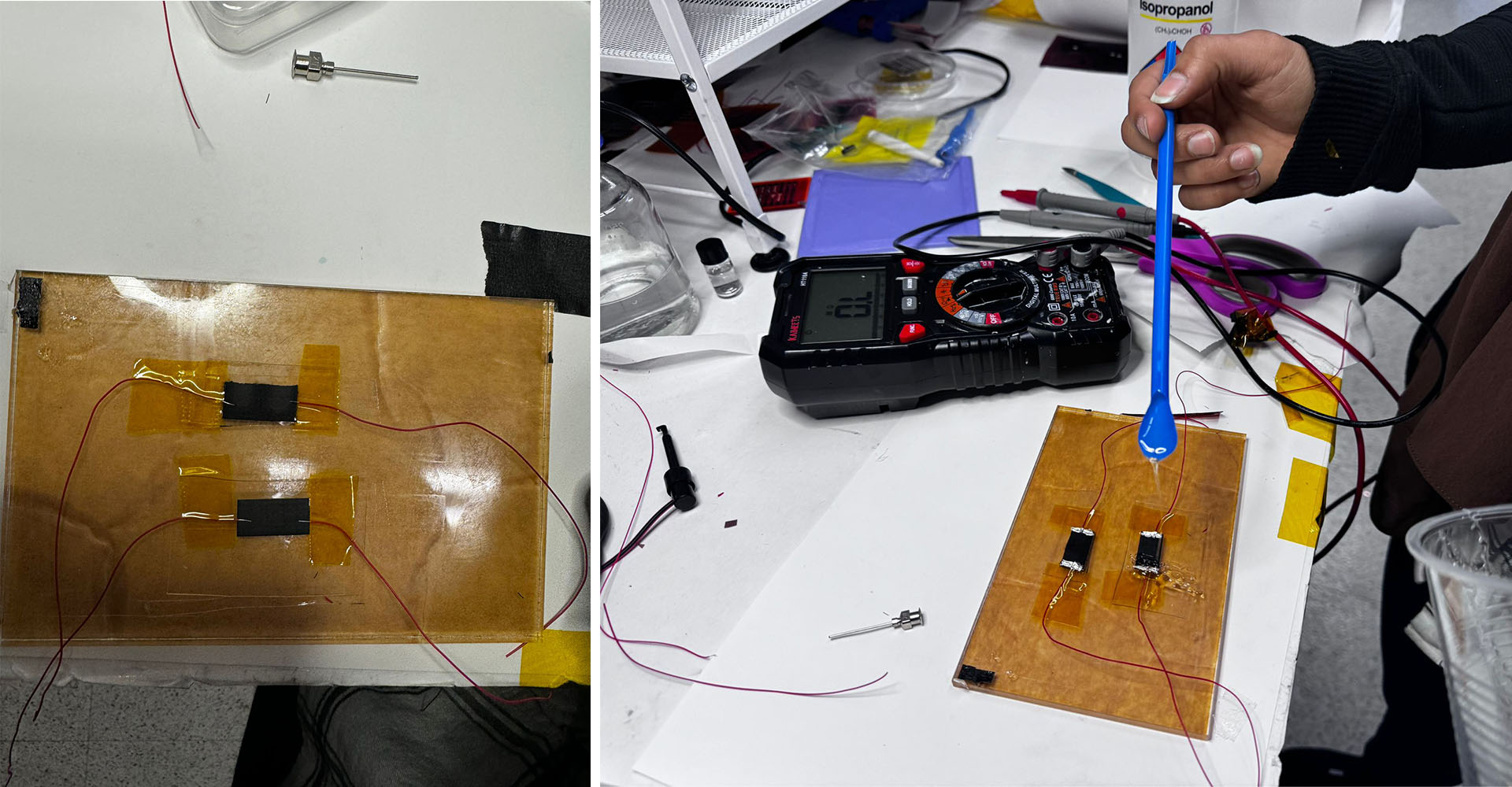
We've developed a graphene pressure sensor using thin paper, which has shown promising results. The sensor's resistance varies between 75 ohms and 460 ohms depending on the applied pressure. You can find a demonstration video of this below.

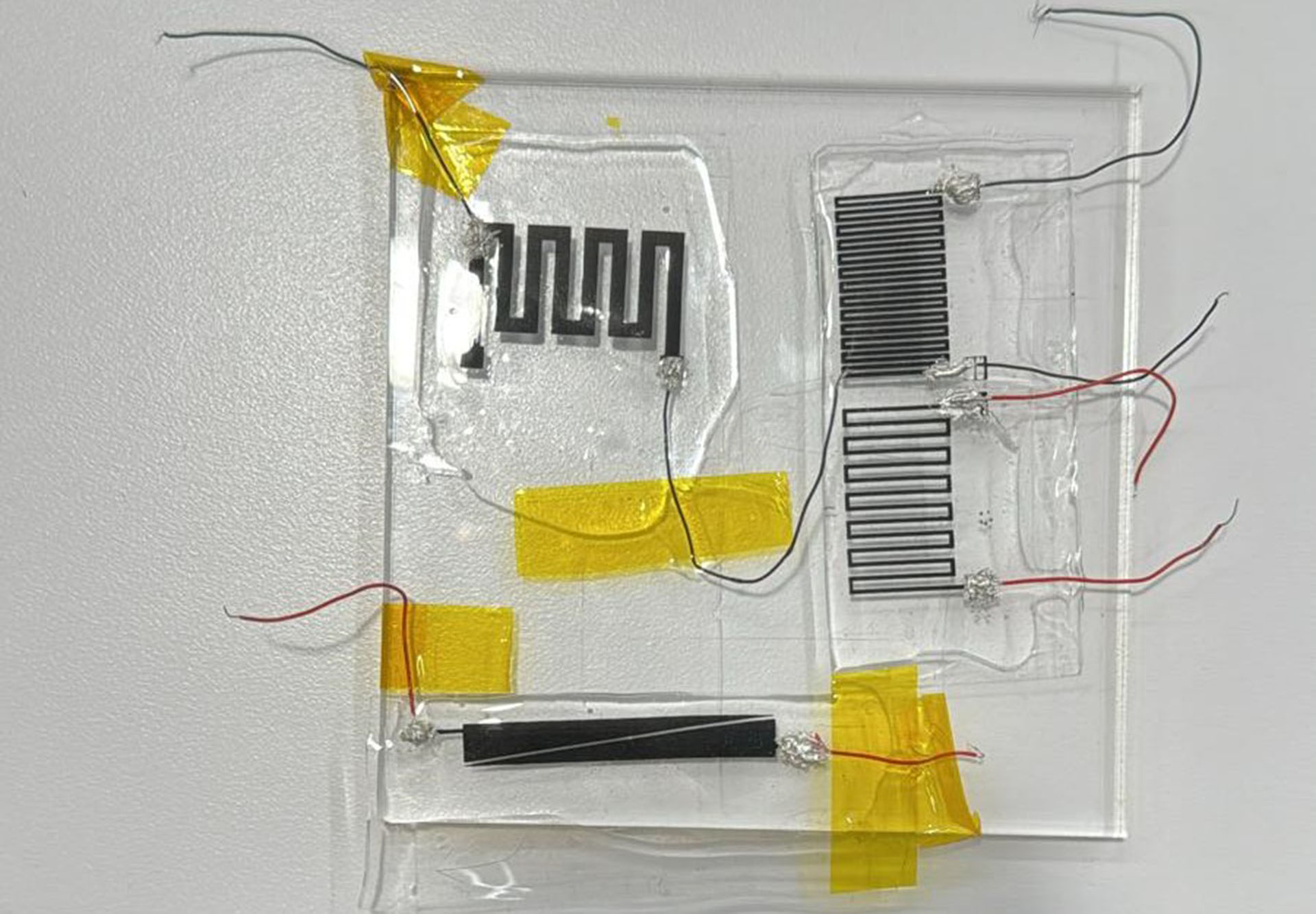
To further enhance the sensor's performance, I decided to redesign it with thin, elongated lines. I created two paths, each 0.5 mm thick. Unfortunately, the settings we used this time burned my paper, resulting in resistance values of 10 megaohms and 35 kiloohms at the ends. Aiming to reduce this to the 1 kiloohm level recommended by Wedyan for optimal pressure sensor performance, I increased the thickness to 2mm and redesigned it. The outcome was outstanding, precisely hitting 1 megaohm. Despite one side being slightly burnt due to a bump in the paper, the resistance values between the two ends were excellent.
For the new 2mm design, I experimented with different settings: while 20% speed and 30% power burned the polyimide, reducing to 8% speed and 10% power yielded much better results, making it 'fleaky enough' for transfer. I plan to attempt the transfer again tomorrow.

Design, Outcomes

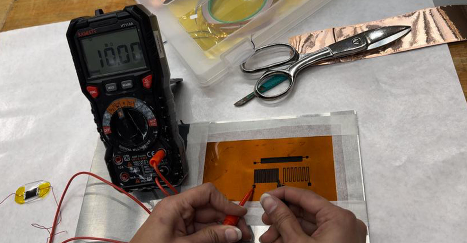


Here is the resistance measurement following the drying of the first PDMS layer.


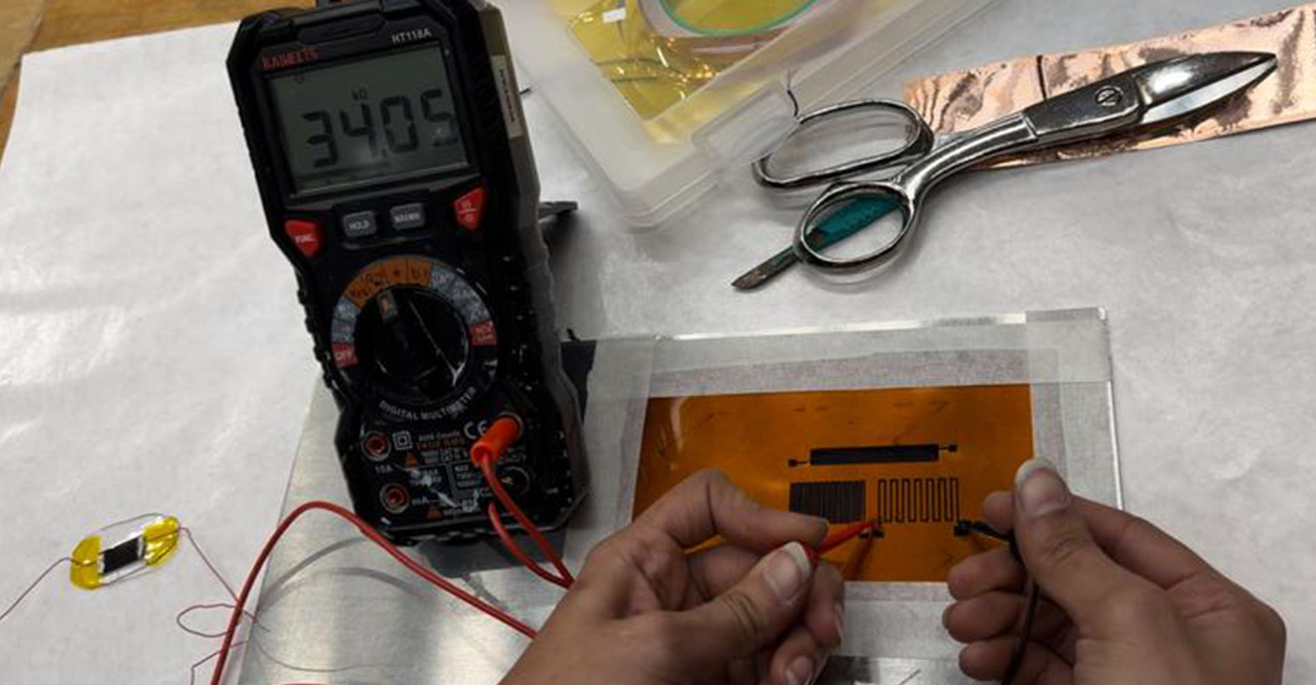
And after the second layer.

Here are the key steps to follow when creating a pressure sensor using the Laser-Induced Graphene (LIG) technique:
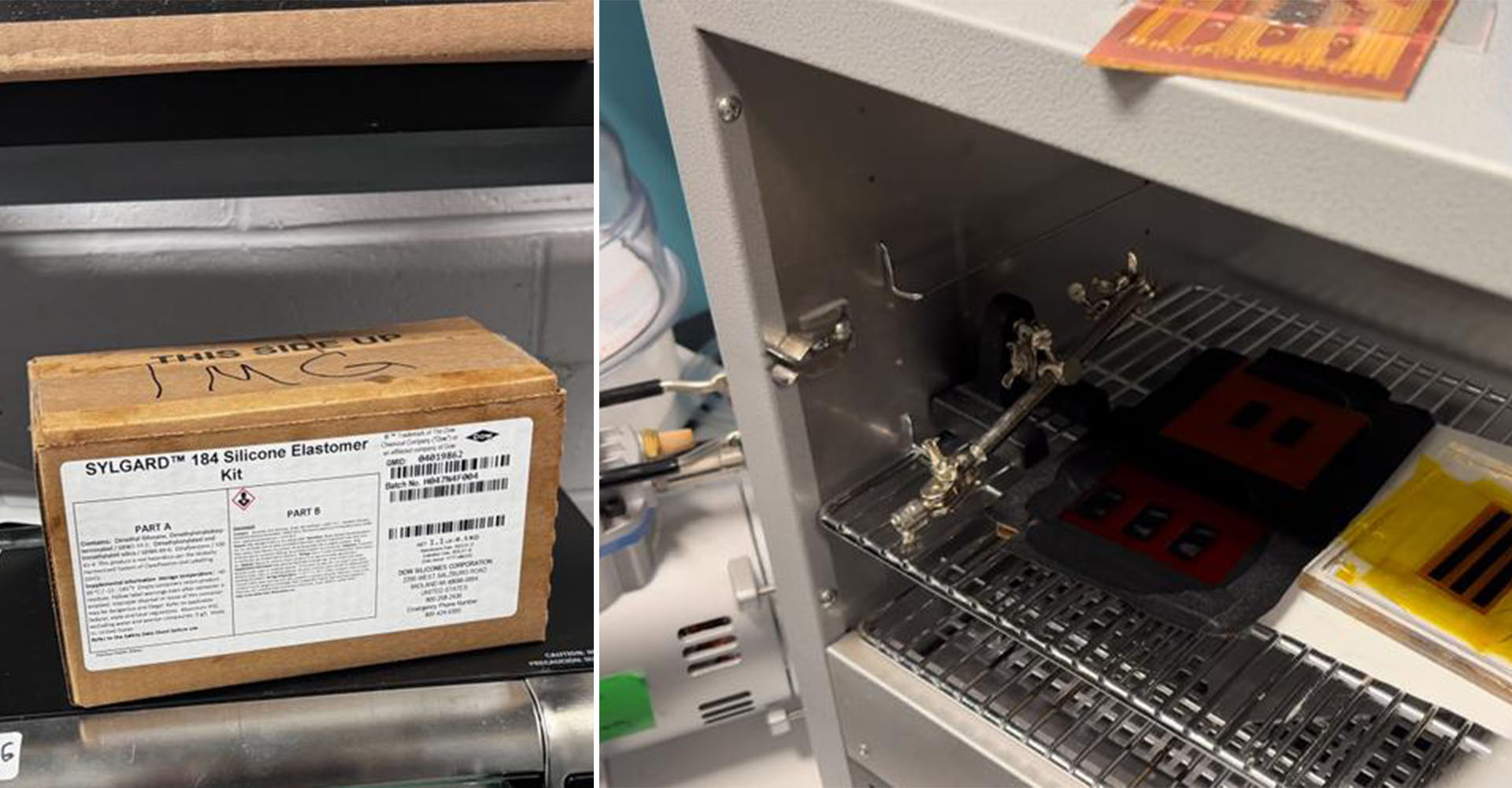
- Optimize Laser Output: Ensure the laser engraving results are of high quality. The graphene should be slightly flaky to facilitate effective transfer but avoid burning it.
- Application of PDMS Layer: After applying the first layer of PDMS, allow it to dry completely. Then, carefully peel off the PDMS from the bottom layer of polyimide to the top.
- Silver Epoxy Application: When applying silver epoxy, aim for a minimal amount. Larger quantities of silver epoxy can inadvertently decrease the sensor's resistance, so a smaller application is preferable.