
For my final project I wanted to build a collective music making machine which is more than a musical instrument; that is a platform to experience rhythm and melody in a completely interactive way. At the heart of this experience is a drum machine, featuring an intuitive step sequencer with eight distinct sequences. It’s about exploration and playfulness – the joy of seeing how different beats and rhythms come together to form something entirely new and unexpected. Multiple people can collaborate, each adding their layer to the composition.
First Trials with DIY Velostat Pressure Sensor
To make this project happen, I tried different methods to make the step sequencer grids interactive. The first method I experimented with was a pressure sensor. For this, I used Velostat placed between copper tapes that I had glued between two pieces of cardboard. I prepared these in two different sizes for my experiments. When I tried a single sensor, I managed to get good results. However, when I added a second sensor, even applying pressure to just one would affect both readings. I believe this was due to them sharing common power and ground connections. But with only a week left until the final project, I didn’t want to invest time in developing such an inconsistent method, so I returned to the capacitive touch sensor that I had been working with all semester.


Capacitive Touch Sensor
I returned to the capacitive touch sensor idea that I've been working on since Input Week.Input Week. In previous weeks, I had experimented with assigning sounds to various plants and living beings by touching them, using MAX MSP. Later, I created my own capacitive touch PCBs using three different techniques. In one method, I connected the touch pads to two digital pins and a 1 megaohm resistor. In the second method, I connected the touch pads to an analog pin and a 1 megaohm resistor, closing the other ends to ground. Finally, I also experimented with a capacitive slider.


Electronics Design
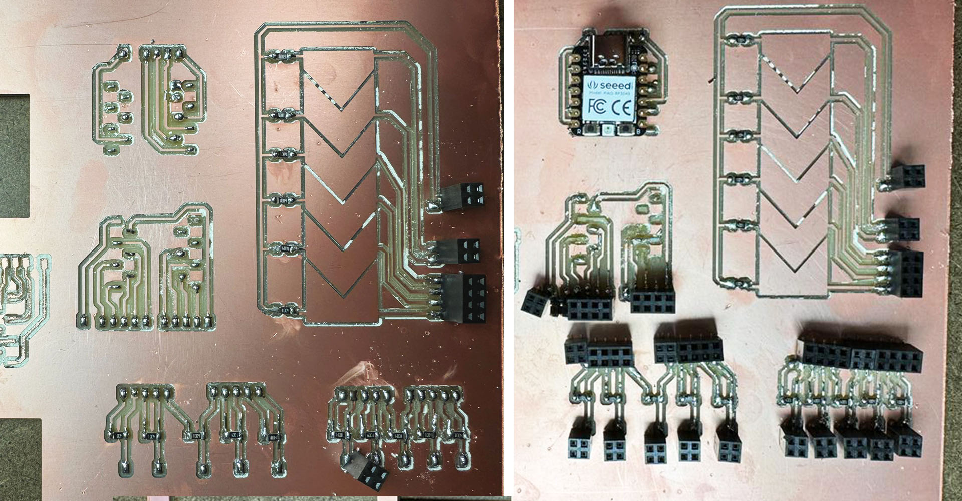
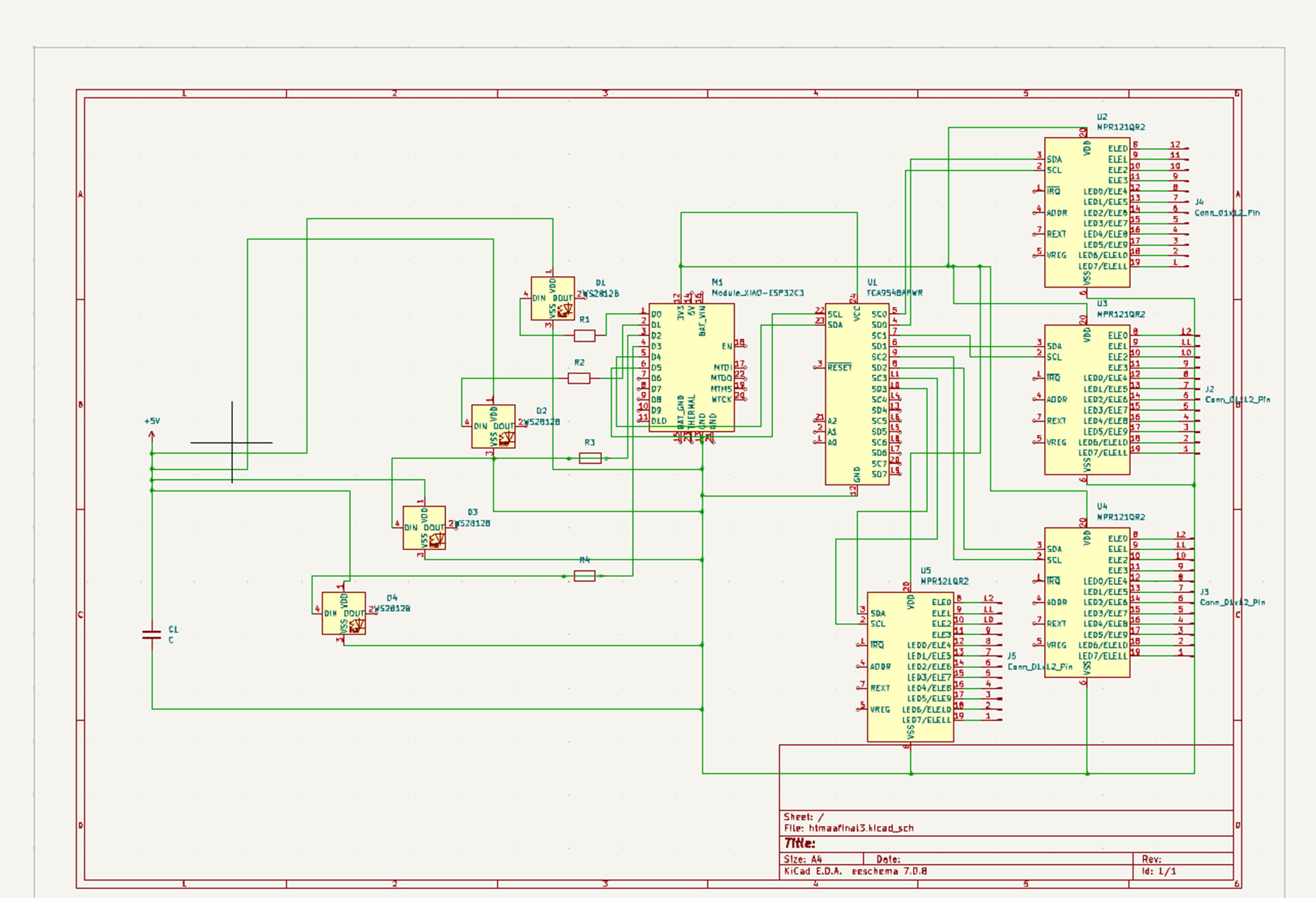
For this project, I initially needed 40 touch pads for the 5x8 step sequencer grid, plus an additional 8 pads for the control panel – two for metro-speed changes, two for genre changes, two for record and delete, and two for navigation, making a total of 48 touch pads. However, after setting up the MAX MSP patch, I had to scale down to 32 touch pads for the 4x8 grid and 8 control pads, totaling 40 pads, due to my computer's CPU limitations and audio slowdowns. Connecting this many touch pads to analog or digital pins directly was impractical. Instead, I decided to use Adafruit's MPR121 12 Capacitive Touch Sensor. Since each sensor has 12 touch pins, I needed to connect four of them to my Xiao ESP32C3 using I2C. To manage this, I used the TCA9548 I2C expander as an intermediary. I connected the four sensors to the I2C expander, and then the expander to the Xiao ESP32C3.
Connecting the four WS2812B LED strips to my Xiao ESP32C3 required both careful planning and precise execution to ensure both functionality and safety. Firstly, I dedicated one digital GPIO pin on the ESP32C3 for each LED strip's data input, ensuring isolated control for each sequence. To protect the data lines and maintain signal integrity, I placed a 330-470 ohm resistor in series with each GPIO pin before it connected to the Din (Data In) pin of the corresponding WS2812B strip. This setup was crucial for reducing noise and voltage spikes that could potentially damage the LEDs. Additionally, I integrated a 1000 µF capacitor between the power supply's positive and ground terminals, which was instrumental in smoothing out the power supply and protecting the LEDs against voltage surges, especially at the moment of power-up. This capacitor acted as a buffer, absorbing and releasing energy, thus stabilizing the voltage supplied to the LEDs.
I also tried to connect the touch pad outputs on the PCBs to the wires coming from the grid by creating different touch pads so that they could communicate with each other.


MAX MSP, Step Sequencer-Drum Machine Patch
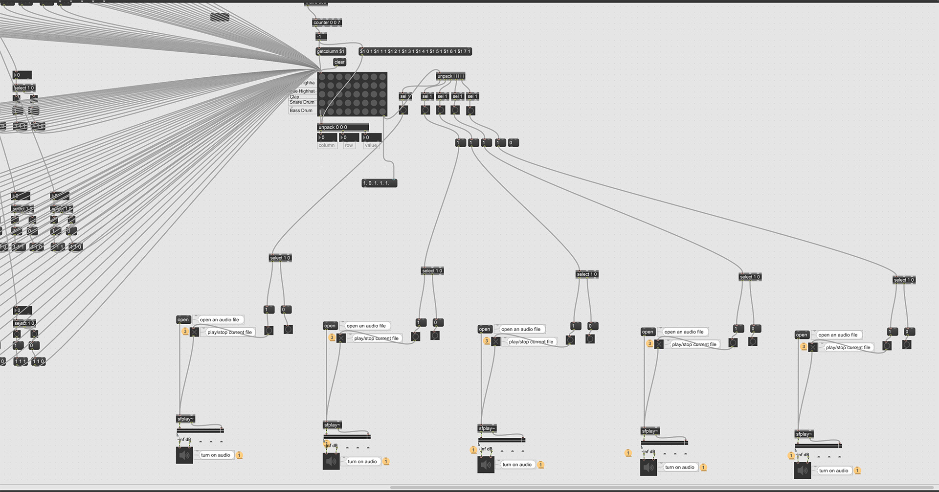
Developing the MAX Patch for this project was a multi-stage process, focusing on establishing a robust interface with the Arduino IDE and creating an interactive sound environment. My first step was to establish a line of communication to receive the serial monitor output from the Arduino IDE. To do this effectively, I utilized a combination of objects in MAX: 'metro' for timing, 'serial' with a baud rate of 9600 for data reception, 'select 13 10' to parse the incoming data stream, 'zl group 2000' to manage data chunking, 'itoa' to convert integers to ASCII, 'fromsymbol' to process the ASCII characters, and 'unpack' to separate the data into usable streams. This initial setup was critical in transforming the raw serial data into a format that MAX could interpret and manipulate.
In the second phase, after successfully receiving binary data (1's and 0's) from the Arduino IDE, I routed each outcome of the 'unpack' object into a 'select 1 0', followed by a 'toggle' for each end. This step was crucial in converting the binary data into toggled states, which could then be used to trigger specific events within the patch. Each of these toggled states was then recombined and connected to a corresponding 'grid' object, with defined x, y, and z coordinates, essentially mapping the binary inputs to a three-dimensional control space within MAX.
Next, I focused on the sound generation aspect. I 'unpacked' the data from the 'grid' object and used 'sel 1' objects for each of the four outcomes. Each of these outcomes was mapped to different sounds, allowing for a diverse auditory experience. This mapping was key to creating a dynamic and responsive sound landscape, where different inputs would trigger varied sonic responses, enhancing the interactivity of the project.
The final step in the MAX Patch creation involved refining the sound playback mechanism. I used 'select 1' once more to isolate specific triggers, which were then connected to 'groove' objects. These 'groove' objects were crucial for sound playback, and I integrated 'open' and 'buffer' objects to load sounds from the computer into the patch. An important consideration was the sound format; I ensured to use WAV files instead of MP3s. WAV files provided better quality and more reliable processing within MAX, crucial for maintaining the clarity and integrity of the sound output in the project


DESIGN

FABRICATION
Waterjet, Cutting Aluminum Sheets
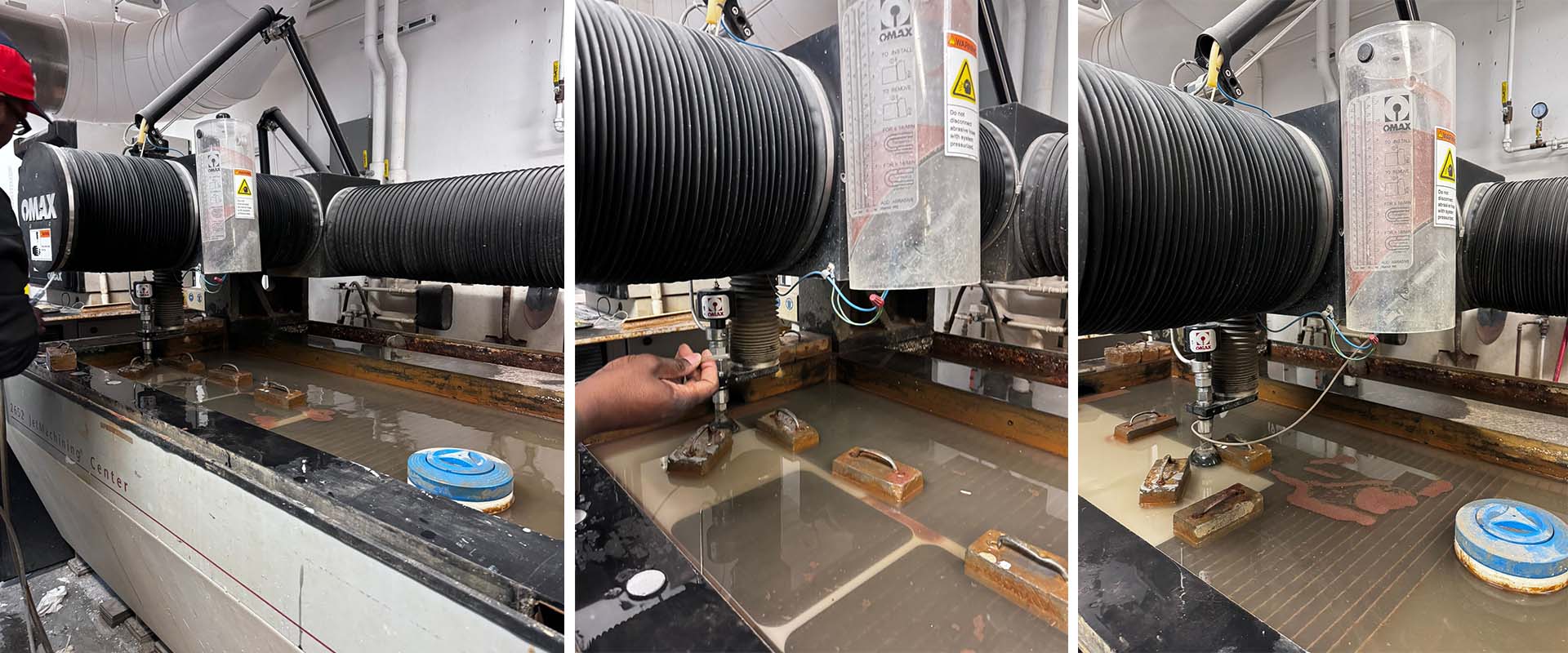
For the fabrication part of the project, I initially experimented with different materials on the touch pads. I tried MDF, acrylic, and aluminum sheets of various thicknesses. The best result came from using an aluminum sheet that was 0.02 inches thick. This sheet was incredibly flexible, bending easily to make contact with the touch surfaces (areas with copper tape) and then returning to its original shape without any issues. To prepare the sheets for cutting, I first needed to resize them from their original dimensions of 36x36 inches to smaller sizes of 24x36 inches and 12x26 inches, making them suitable for cutting on the waterjet. The cutting process took around an hour and a half, but the outcome was smooth and met my expectations perfectly.
Shah moderated the waterjet, and carefully placed the material, calculated the route and also added necessary weights onto the material. The material was trying to float in water, so that Shah was really careful in placing weights.


Since the material was very lightweight, even a slight bulging of just 1 millimeter could cause issues during the waterjet cutting process. The water's recoil when hitting the bulged areas would sometimes cause the waterjet's nozzle to clog with garnet sand. We encountered this blockage issue about 5-6 times. Each time, Shah had to remove the pipe connecting the nozzle to the garnet bucket and clean it with compressed air. He also used the compressed air to stop the flow of garnet sand by directing it at the bucket's outlets. However, whenever the material bulged even slightly, we faced the same problem of nozzle clogging.
CNC Cutting
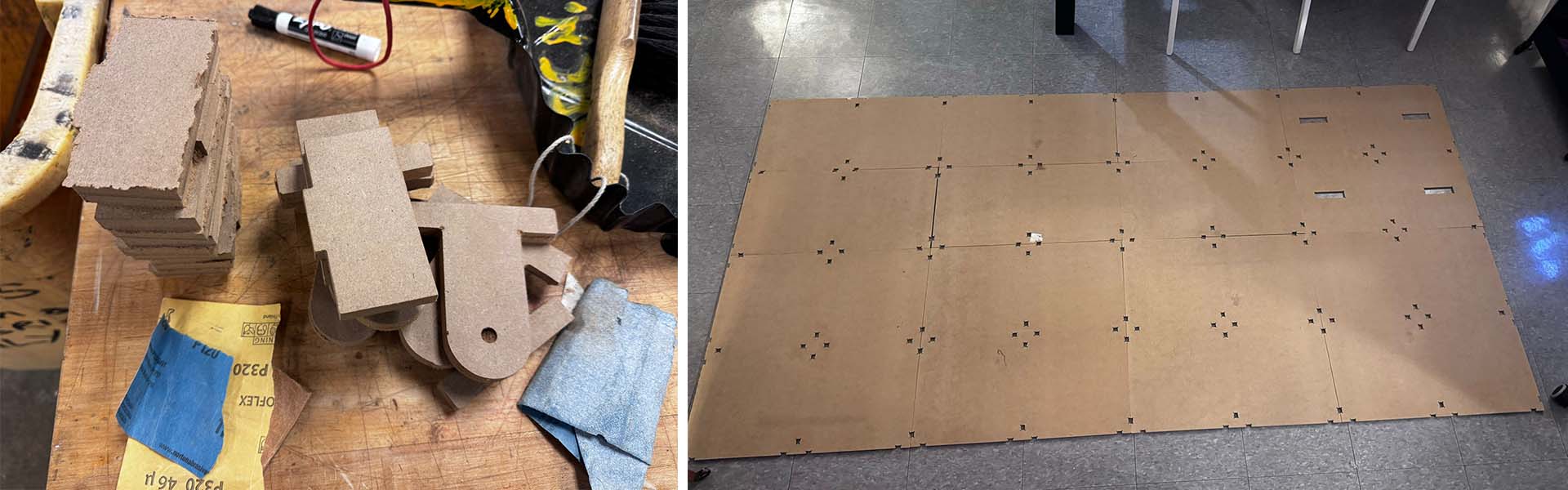
Despite expecting a straightforward CNC process, it turned out to be quite time-consuming, primarily because many people were rushing to complete their final assignments at the last minute. I frequently found myself waiting for Chris, David, or Sloan to prepare the G-code. For the panels that I planned to place under the grid, I used 0.25-inch MDF sheets, cutting them from 2x4 feet sheets. For creating the connecting details to join these panels together, I utilized 0.5-inch panels.


The connection pieces I wanted to cut from the 0.5-inch panels were very small, which led Chris to suggest that I combine them first and then shape them using a bandsaw. This was because their small size could cause them to shift during the cutting process, potentially compromising the accuracy of the cuts.
Once the cutting was complete, I took the pieces to the bandsaw to shape them into their final forms and then sanded them down. I found that 220-grit sandpaper gave the best result. Finally, I used a hammer to carefully assemble the sanded pieces together.

Lasercutting
When it was finally my turn to use the CNC, uncertainty about whether some parts would be cut in time led me to decide to use the laser cutter for them. First, I resized the parts to fit the 24x36 inch bed of the laser cutter. Then, I proceeded with the laser cutting process. However, cutting through the 0.25 inch MDF proved to be more challenging than anticipated, requiring me to pass over each cut 15 times to achieve the desired depth. I experimented with various settings, but ultimately the best results came from using a configuration of 500 dpi, 10% speed, and 100% power.


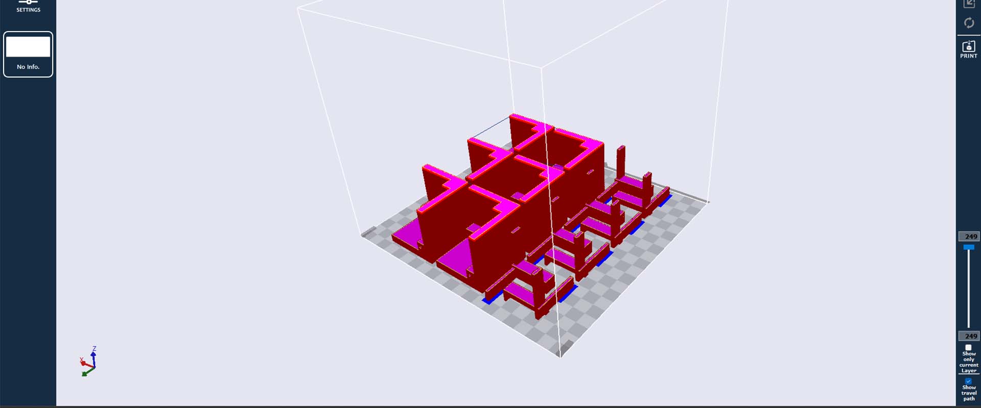
3D Printing
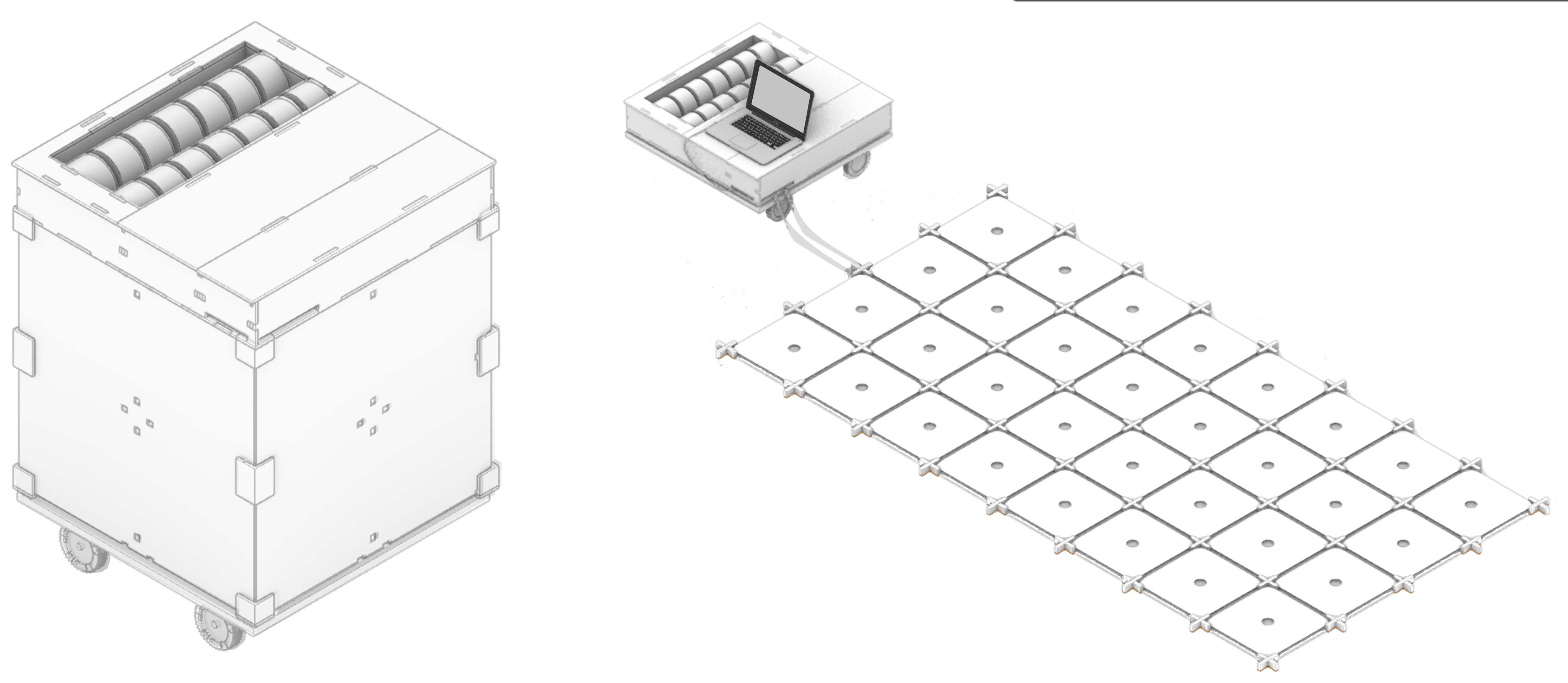
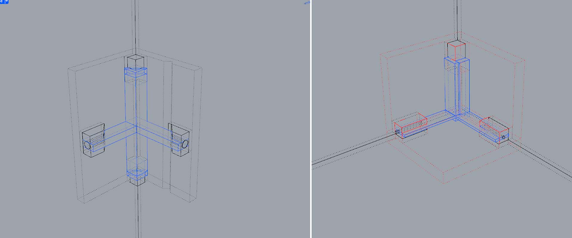
To ensure that my newly created musical device was portable, I envisioned a system where the MDF panels underneath it could transform into a box-like structure. To achieve this, I designed 3D printed connection details. These details were specifically crafted to replace the MDF connectors and form a box when the device is assembled and the MDF connectors are removed. The design allows for external elements to enter these holes, clamping the MDF panels in place, and then securely locking with an internal 3D printed locking mechanism. This approach not only enhanced the structural integrity of the device but also added a layer of versatility to its assembly and disassembly process.
In addition to these connection details, I also designed four wheels for added mobility. I produced these wheels using a 3D printer, ensuring that they were sturdy enough to support the weight of the device while providing smooth movement. The incorporation of wheels was a crucial aspect of the design, as it significantly enhanced the portability of the device, making it easy to relocate and set up in different environments.


Casting
To facilitate the use of this multiuser musical device by a single individual if desired, I decided to produce some weights. I used Cementall for casting, pouring it into 2-inch high and 4-inch diameter silicone molds. To enhance their appearance, I also incorporated white acrylic paint into the mix. I added the paint at a ratio of one-tenth of the total volume of water and Cementall combined, effectively using a 1/4 ratio of water to Cementall and then adding the white acrylic paint to constitute 10% of the total volume.

Assembly
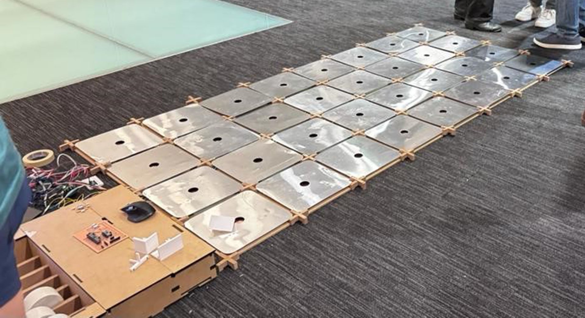
When I reached the assembly stage, it was time to bring all the components together. I began by placing and numbering the bases I had cut earlier. Then, in the center of each, I affixed 15cm x 15cm copper tapes. Subsequently, I wired all these copper areas together, gathering the wires at one point. I left about 1 meter of wire length for each and secured them in place with tape. The final step in this phase was to install the connectors and position the aluminum pieces.
The parts that were cut using the laser cutter were designed to interlock, which facilitated an easy and straightforward assembly. I joined these pieces together, completing the setup process efficiently. This method of interlocking components not only streamlined the assembly but also contributed to the overall structural stability of the device.


Presentation
After completing the assembly, I proceeded to test the PCB that I had made earlier. Unfortunately, the PCB did not function as expected. To diagnose the issue, I decided to run a series of diagnostic codes to check if the microcontroller was receiving any signals from the I2C expander. This step was crucial to pinpoint the problem, as it would help determine whether the issue was with the microcontroller's communication or something else in the circuit. The results of these tests, however, came back negative, indicating that the microcontroller was not successfully communicating with the I2C expander. THE I2C EXPANDER WAS BROKEN AND I DID NOT REALISED THIS UNTIL I TRY IT ON THE VERY LAST DAY.
#include

void setup() {
  Serial.begin(9600);
  Wire.begin();

  for (int channel = 0; channel < 8; channel++) {
    Serial.print("Selecting channel ");
    Serial.println(channel);
    selectI2CChannel(channel);
    delay(1000); // Adding a delay for stabilization
    scanI2CBus();
  }
}

void loop() {
  // Nothing to do here
}

void selectI2CChannel(int channel) {
  Wire.beginTransmission(0x70); // TCA9548 I2C address
  Wire.write(1 << channel);
  Wire.endTransmission();
}

void scanI2CBus() {
  byte error, address;
  int nDevices;

  Serial.println("Scanning...");

  nDevices = 0;
  for (address = 1; address < 127; address++ ) {
    Wire.beginTransmission(address);
    error = Wire.endTransmission();

    if (error == 0) {
      Serial.print("I2C device found at address 0x");
      if (address < 16) Serial.print("0");
      Serial.println(address, HEX);
      nDevices++;
    } else if (error == 4) {
      Serial.print("Unknown error at address 0x");
      if (address < 16) Serial.print("0");
      Serial.println(address, HEX);
    }
  }
  if (nDevices == 0) {
    Serial.println("No I2C devices found\n");
  } else {
    Serial.println("done\n");
  }
}
    code
    #include

void setup() {
  Serial.begin(9600);
  Wire.begin();

  for (int channel = 0; channel < 8; channel++) {
    Serial.print("Selecting channel ");
    Serial.println(channel);
    selectI2CChannel(channel);
    delay(1000); // Adding a delay for stabilization
    scanI2CBus();
  }
}

void loop() {
  // Nothing to do here
}

void selectI2CChannel(int channel) {
  Wire.beginTransmission(0x70); // TCA9548 I2C address
  Wire.write(1 << channel);
  Wire.endTransmission();
}

void scanI2CBus() {
  byte error, address;
  int nDevices;

  Serial.println("Scanning...");

  nDevices = 0;
  for (address = 1; address < 127; address++ ) {
    Wire.beginTransmission(address);
    error = Wire.endTransmission();

    if (error == 0) {
      Serial.print("I2C device found at address 0x");
      if (address < 16) Serial.print("0");
      Serial.println(address, HEX);
      nDevices++;
    } else if (error == 4) {
      Serial.print("Unknown error at address 0x");
      if (address < 16) Serial.print("0");
      Serial.println(address, HEX);
    }
  }
  if (nDevices == 0) {
    Serial.println("No I2C devices found\n");
  } else {
    Serial.println("done\n");
  }
}

Upon discovering that my initial PCB was not functioning correctly due to unfunctioning TCA9548 I2C expander, I moved forward with fabricating a new one, aiming to successfully connect three different MPR121 sensors to the Xiao ESP32C3 via their I2C addresses and the ADDR pins on the sensors. Theoretically, this setup should work if I connected the first sensor normally, linked the second sensor's ADDR pin to the ESP32C3's ground pin, and connected the third sensor's ADDR pin to the ESP32C3's power pin. This configuration would assign each sensor a unique I2C address, allowing the microcontroller to communicate with all three sensors individually.
However, my attempts with this new PCB also failed to yield the desired results. As the deadline loomed and it was already the midnight of the last day. I had to quickly find a solution to make the system operational. With limited time and the urgency of the situation, I decided to revert to using a breadboard for troubleshooting and testing. My focus was on creating a functional prototype on the breadboard, which would enable me to understand and resolve the issues that were preventing the PCBs from working as intended.

                                    #include
#include

// Create instance for the MPR121 sensor with a unique I2C address
Adafruit_MPR121 cap1 = Adafruit_MPR121();

// Unique I2C address for the sensor
const uint8_t MPR121_ADDR1 = 0x5A; // Address for the sensor

void setup() {
  Serial.begin(9600);
  Wire.begin();

  if (!cap1.begin(MPR121_ADDR1)) {
    Serial.println("MPR121 not found, check wiring");
    while (1); // Halt execution if sensor not found
  }

  // Set touch and release thresholds for all electrodes
  cap1.setThresholds(2, 1); // Set touch threshold to 2 and release threshold to 1

  Serial.println("MPR121 sensor found and initialized with custom sensitivity!");
}

void loop() {
  // Read touch data from the sensor
  uint16_t touch1 = cap1.touched();

  // Send each touch pad state as a separate value, separated by spaces
  for (int i = 0; i < 12; i++) { // MPR121 supports up to 12 touch points
    Serial.print((touch1 & (1 << i)) ? "1" : "0");
    if (i < 11) {
      Serial.print(" "); // Add a space after each number except the last
    }
  }

  // End the line after sending all touch pad states
  Serial.println();

  delay(100); // Adjust delay as needed
}
In my breadboard setup, I successfully established communication with a single sensor. In the coming days, I plan to try a new method. This involves connecting three different sensors to the GPIO pins in a standard fashion. My goal is to find libraries that facilitate communication with capacitive touch sensors, and then I will create a new PCB based on this approach. However, with the current state of the project, I was able to present the machine in a semi-functional form on the final day, successfully running it albeit with some limitations. This partial success was a crucial step in the development process, demonstrating the potential of the device and setting a foundation for future improvements and iterations.

What does it do? The machine is a 4x8 grid step sequencer, equipped with touch pads, designed to enable collective music creation. It allows multiple users to interact and compose music together, making it a unique tool for collaborative musical expression.
Who's done what beforehand? There have been various grid step sequencers developed previously. I drew inspiration and technical guidance from YouTube tutorials, particularly for integrating Arduino IDE serial data with Max MSP and working with the grid object.
What did you design? I designed the entire system encompassing the step sequencer, which includes both the hardware and software components, as well as the PCB. The design process involved conceptualizing the interactive experience and ensuring the seamless integration of various electronic elements.
What materials and components were used? The machine is built using materials such as 0.25 inch MDF, 0.5 inch MDF, 0.02 inch aluminum sheets, white PLA, CementAll, memory foams, white acrylic paint, copper tape, and numerous wires and tapes. The electronic components include 4 MPR121 touch sensors, 1 TCA9548 I2C expander, and 2 Xiao ESP32C3 microcontrollers.
Where did they come from? Most of the materials and electronic boards were purchased. The school provided the white PLA and Xiao ESP32C3 microcontrollers.
How much did they cost? The total cost of the materials and components was approximately $588.
What parts and systems were made? I fabricated the 3D printed parts, the MDF surfaces, and developed the touch-sensitive system comprising copper-foam-aluminum layers.
What processes were used? The processes involved programming with Max MSP and utilizing the MPR121 touch sensor library to facilitate the touch interaction.
What questions were answered? The main question addressed was how to create a portable, interactive, multi-user musical device that leverages touch sensors and sound mapping for collective music-making.
What worked? What didn't? Most aspects of the device worked seamlessly, except for the PCB. The failure of the PCB was mainly due to a malfunctioning I2C expander. Due to the time constraints before the presentation, I couldn't develop a functional PCB in time.
How was it evaluated? Considering the project's scope and the time frame, I'm quite satisfied with the outcome. The main challenge was the decision to start this project in the last week, requiring rapid design and fabrication within a very tight schedule. With a few more days, I could have resolved the PCB issue. Despite changing my final project idea late in the semester and facing time constraints, I'm thrilled with the result and look forward to future developments, where I plan to fully operationalize the device and observe user interactions.
What are the implications? This project has spurred my interest in researching interactivity in public spaces and inspired me to create more interactive devices. I am excited about the learning process this project entailed, combining various skills acquired throughout the semester. It was challenging but immensely educational and rewarding.