For this week's assignments in my How to Make (Almost) Anything, we're diving into the world of 3D printing and scanning. As part of our group assignment, we'll be testing the design rules for our 3D printers, ensuring precision and accuracy in our future creations. On the individual front, I'm tasked with designing and 3D printing an object that defies traditional subtractive manufacturing techniques.
3D Scanning
Scanning with Iphone, Lidar Technology
For my assignment on scanning objects, I chose to scan various meals throughout the week, given their diverse characteristics such as shiny, matte textures, different colors, and various forms. To start, I attempted to scan these meals using my phone's Lidar Feature. I experimented with several scanning apps, including 3D Scanner, SureScan 3D, proAR, Modified, ScandyPro, Qclone, Matterport, 3D Scanner App, Canvas, and Metascan. After multiple unsuccessful attempts, I eventually achieved promising results with two of these apps: 3D Scanner App and Metascan.
In the case of the 3D Scanner App, I began by creating scans using 30-70 photos taken of each meal. Unfortunately, the initial results were disappointing. I initially attempted to maintain the plate's position while circling it to capture images from different angles.

Next, I improved the lighting conditions, but the results remained unsatisfactory in the first two photos. I then decided to keep the plate stationary while rotating myself to capture each photo, resulting in slightly better outcomes. However, the 3D shape of the meal still appeared distorted when viewed from a lower perspective. It became apparent that the app's point cloud generation process did not capture areas under the plate, erroneously merging the plate and table in some photos.

Ultimately, I opted to create the scan using a video instead of photographs, which surprisingly produced better results. The video consisted of 291 frames, and the increased frame count contributed to improved quality. However, the bottom of the plate remained empty. I also downloaded the OBJ version and examined it for further control.


Subsequently, I used the Metascan app for the same purpose and achieved better results. Initially, I tried keeping the camera fixed while rotating the plate for each photo, but the results were unsatisfactory. However, when I scanned a Sicilian Cannoli with a fixed plate and a rotating camera, I succeeded. This scan, comprising 20 photos taken from various angles around the plate, proved to be successful. Even though the settings were configured for medium detail, the resulting scan was significantly better.

Scanning with Revopoint Pop 2
The Revopoint Pop 2 device was positioned in room 4-312. This device featured a rotating base and a scanner attached to a tripod. During my initial trial, my goal was to find the optimal position for scanning. Once I had achieved this optimal setup, I began scanning a banana. Throughout the scanning process, I kept the tripod stationary while only allowing the banana to rotate. Initially, when the scanning was completed but not yet processed, the model appeared to be unsuccessful. However, once the processing was complete, the results turned out quite well. The scan produced a satisfying outcome, although there were areas at the top and bottom that remained unscanned.
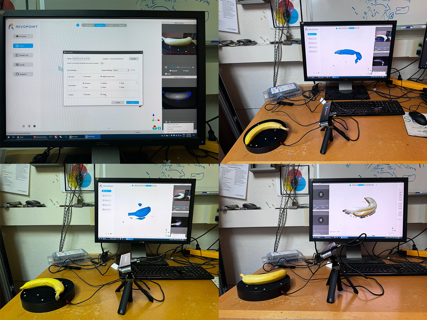
Next, I attempted to reposition the tripod while scanning the banana. Unfortunately, my movements were somewhat fast, and the banana itself was rotating on its surface. The scanning results were highly unsatisfactory as the scanner struggled to keep up with the rapid motion.

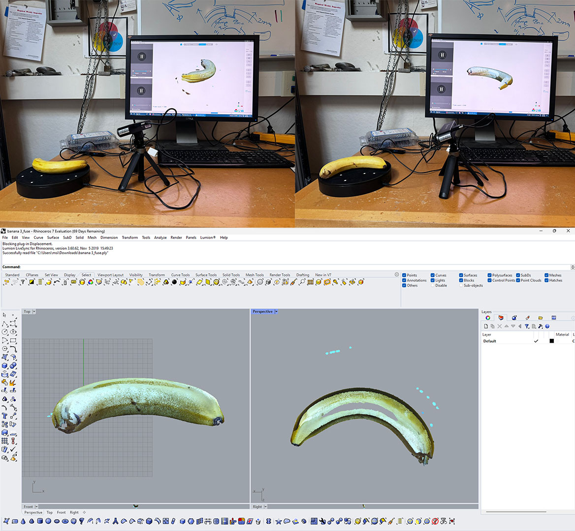
Ultimately, I decided to enhance the scan by trimming the end of the banana so that it could fit securely in the base. With this adjustment, I proceeded to scan while slowly moving the tripod around the banana. This approach yielded the best results among all my attempts, although there was still an area at the bottom of the banana that remained unscanned.
Subsequently, I made the decision to export the scan as both .obj and .ply files. Unfortunately, the .obj version failed to open in Rhino, despite my various attempts. On the other hand, the .ply version did open, but it appeared as a point cloud rather than a mesh. This presented a challenge as it prevented me from 3D printing my scans.

3D Printing
First Trials, Printing Settings, Raft and Thicknesses,
For my 3D printing assignment, I faced quite a challenge in deciding what to work on this week. I ventured into various experiments, which turned out to be a blessing in disguise because I encountered a multitude of unique problems to tackle. Initially, I embarked on printing three distinct fabric-like patterns, each with varying thicknesses. The first pattern consisted of a 0.4 mm thick grid, followed by a 0.8 mm version, and finally, a chain-like structure.

However, during the printing process, I opted to utilize a raft generated by the 3DWOX slicer program. Unfortunately, this decision proved problematic for the 0.4 mm grid-like surface, as it adhered too strongly to the raft. Consequently, when I attempted to remove it, the gridal structure ended up getting damaged.

The 0.8 mm surface, when removed, displayed some minor cracks but still served its purpose as a flexible surface, aligning with the direction of the holes within it.

Conversely, the chain structure encountered a different challenge as it detached from its raft during the printing process. Consequently, the portion without a raft exhibited flexibility, resembling a chain, while the section attached to the raft proved difficult to separate and remained quite rigid.

Further Trials, Chains and Fabric-like Printings, Flexibility and Durability
I embarked on a chain testing experiment using models I found online on UltimakerThingiverse.com. I printed all of these chains without the use of a raft to determine if it would simplify the process. Initially, I had to closely monitor the first few layers due to concerns that the filament might not adhere correctly to the bed. Fortunately, this did not pose a problem. It was very easy to remove the prints out of cartilage and also did not created any cracks.
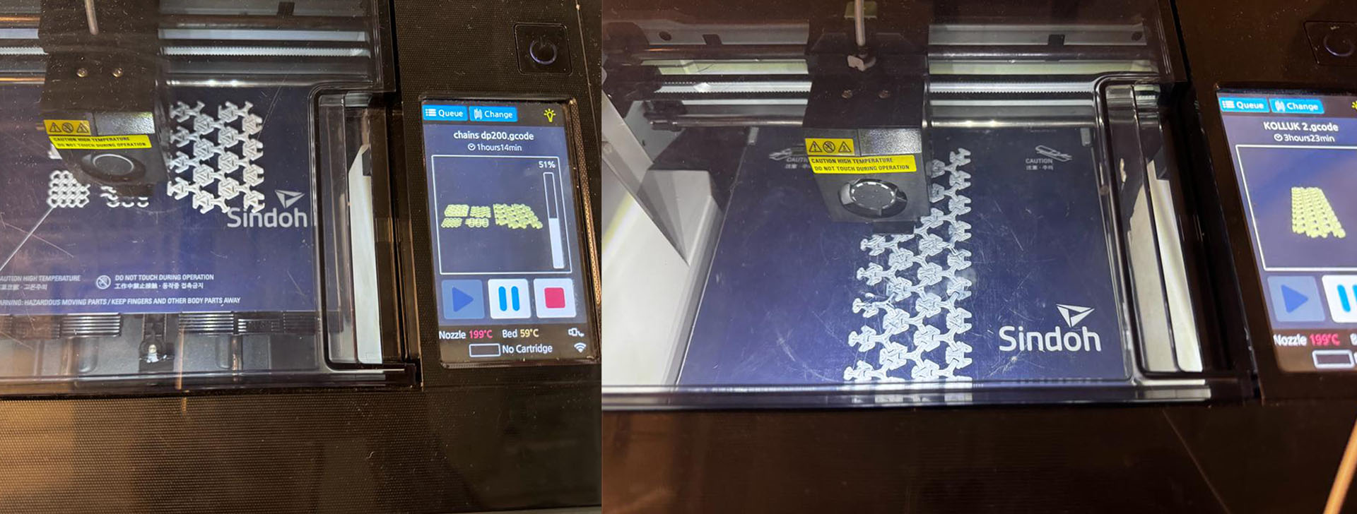
For my first test, I decided to work with the NASA chainmail model, which, as it turned out, was the least flexible among all the chains I tried. Next, I experimented with the Treeflake structure, which consisted of hexagonal structures connected by triangular joints. This chain displayed remarkable flexibility on all sides and behaved almost like a rough fabric. However, when I scaled down the Treeflake structure to 50 percent of its original size, it became quite fragile, although it still retained some flexibility. Lastly, the parametric chain structure proved to be the most flexible option, even though it was small in scale. It exhibited greater durability compared to the Treeflake joints.


Lace Collar with Flowers
For this week's 3D printing assignment, my goal was to craft an intricate, delicately thin lace collar adorned with a decorative flower button. Leveraging my previous experience, I knew that a thickness of 0.8 mm would yield a surface that was both durable and sufficiently flexible. Additionally, incorporating some holes into the design would enhance its flexibility.
I located a lace pattern and proceeded to print it at a 0.8 mm thickness. Unfortunately, the size constraints of the 3D printer prevented me from creating a complete collar with a back section. Nevertheless, I devised a solution by crafting two separate sides that could be seamlessly connected using the flower button as the centerpiece.
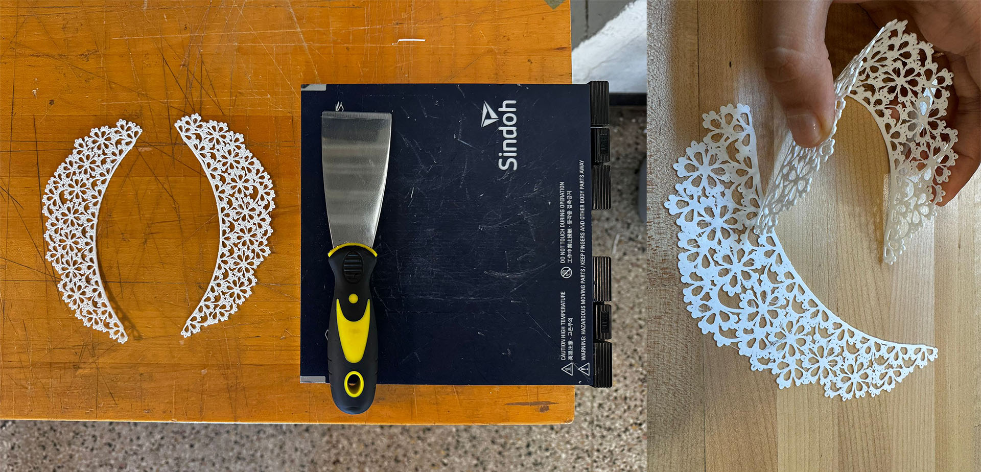
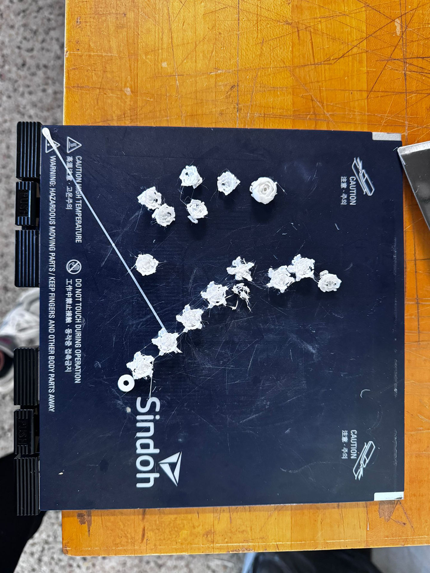
The 3D printed lace collar, which was printed directly onto a surface without any additional structure or raft, was a success in terms of adherence to the surface and ease of removal. However, the intricate flower buttons proved to be a challenge due to their small size. Some of these miniature flowers were not fully printed, resulting in incomplete or unrecognizable flower shapes. Furthermore, the ones that did manage to form were extremely delicate, making them susceptible to breakage.
Continuing my exploration of collar design, I decided to incorporate butterfly drawings that I had discovered online. I compiled these butterfly images into a cohesive collar design and then used Adobe Illustrator's "Image Trace" feature to convert them into vectors. Subsequently, in Rhino, I transformed these vectors into a 3D model and added support structures in certain areas.
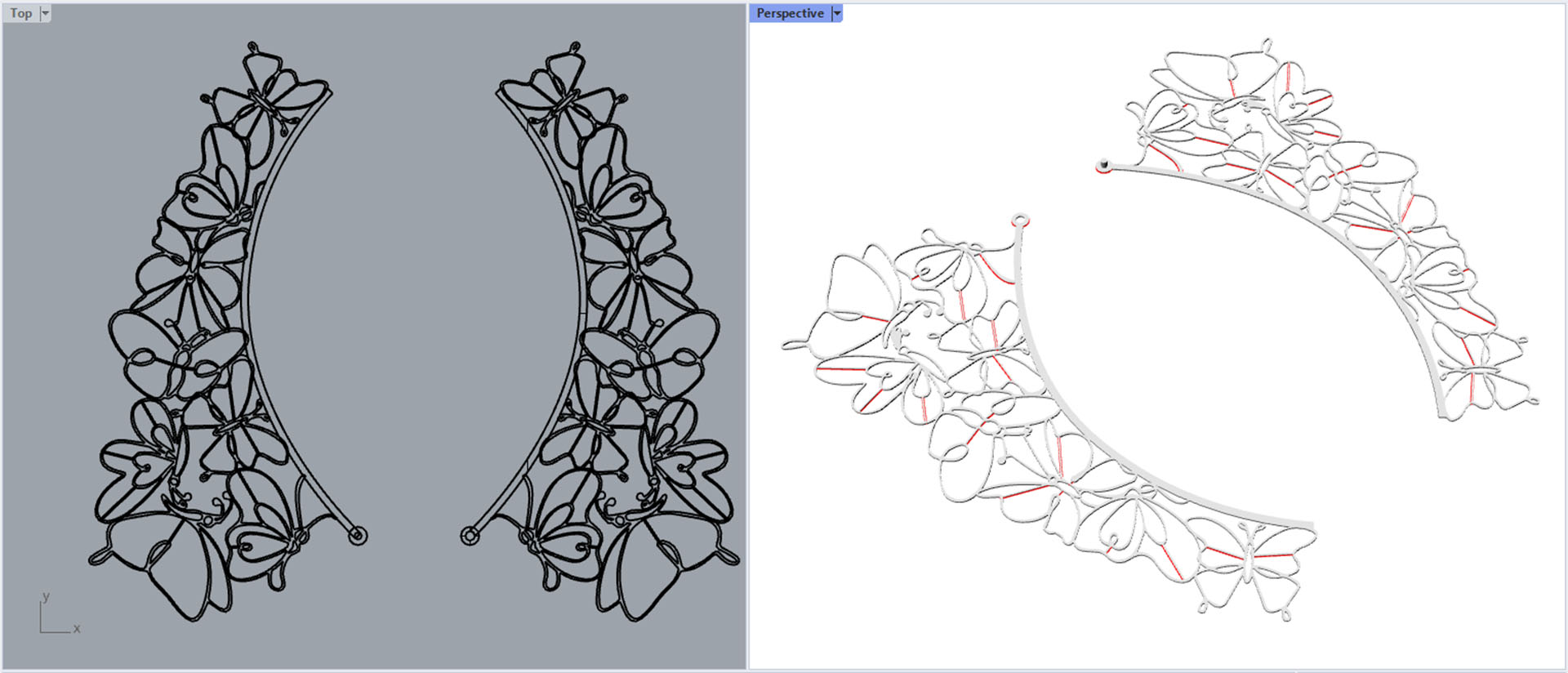
For the printing phase, I aimed for a 0.8 mm thickness, and, similar to my previous experience, I opted to print it without any additional structure or raft. Unfortunately, I encountered an issue during printing where the first layer failed to adhere properly to the build surface. This forced me to halt the printing process prematurely.

Design of an 3D Printed Lace Veil and Printing
In Turkish culture, lace is something that everyone at least my age has seen in their home. Sometimes he goes so extravagant that this lace is knitted onto a computer monitor, a washing machine, a vacuum cleaner, and even the house cat.
The pinnacle of this lace obsession, though, is the television cover. When TVs began to pop up in homes across Turkey, even in the most remote and affluent rural areas, they've been given places of honor in living rooms. Housewives of yore seemed to have an unspoken pact, dressing their televisions in various lace covers - some for practicality, to keep the dust at bay, and others purely for aesthetic reasons.
Now, for my homework, I've decided to give this tradition a 21st-century twist. We recently got a brand new TV, which has been sitting idle for the past three months. My idea is toTo craft a 3D printed lace cover for it.

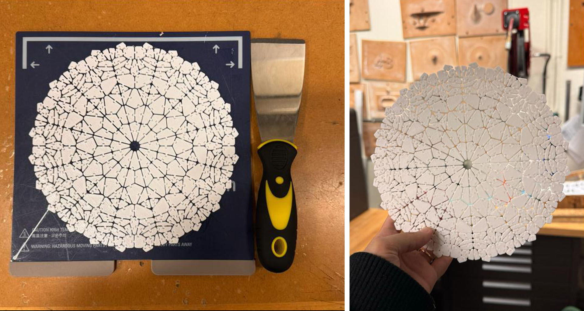
I start the design of my lace cover with a very simple grasshopper code. I determine a point and create a cluster. In this cluster, I try values such as pattern size, division, offset, fillet and extrusion. In order for the pattern I created to bend on the TV and give a lace look, I set the division to 12 and 7, the offset to 0.5 mm, and the fillet to 1 mm. I set Extrusio to 0.4mm, which I've done before and had good results with. Below you can see the visual results of these changes in comparison.


Next, I infuse additional intricacies into my lace design, incorporating elements from my previous successful attempt with a treeflake structure. I start by creating openings using boolean difference and then insert fitting components within these spaces. The success of the Treeflake design lay in its hollow inner gear section, which allowed for flexible movement. To replicate this effect, I perform a final boolean difference, revealing the threaded part and enhancing the design's resemblance to authentic lace.


Then I prepared my g-code as I did before with no raft and no support, so that I can easly take it out and easily flex it.

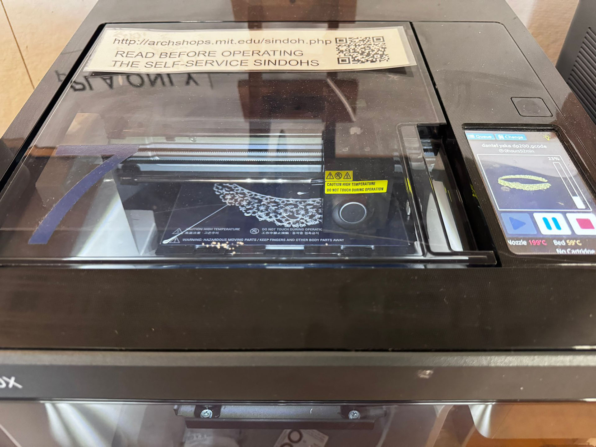
It took nearly nine and a half hours for my lace design to be printed on the 3D printer. This time, we opted for printing without a raft, using the Sindoh 3dwox1 printer. The printer's flexible tray made it easy to remove the lace. However, the lace was more fragile than anticipated. The connecting parts were finer compared to the Treeflake structure I had printed previously, resulting in some breakage.
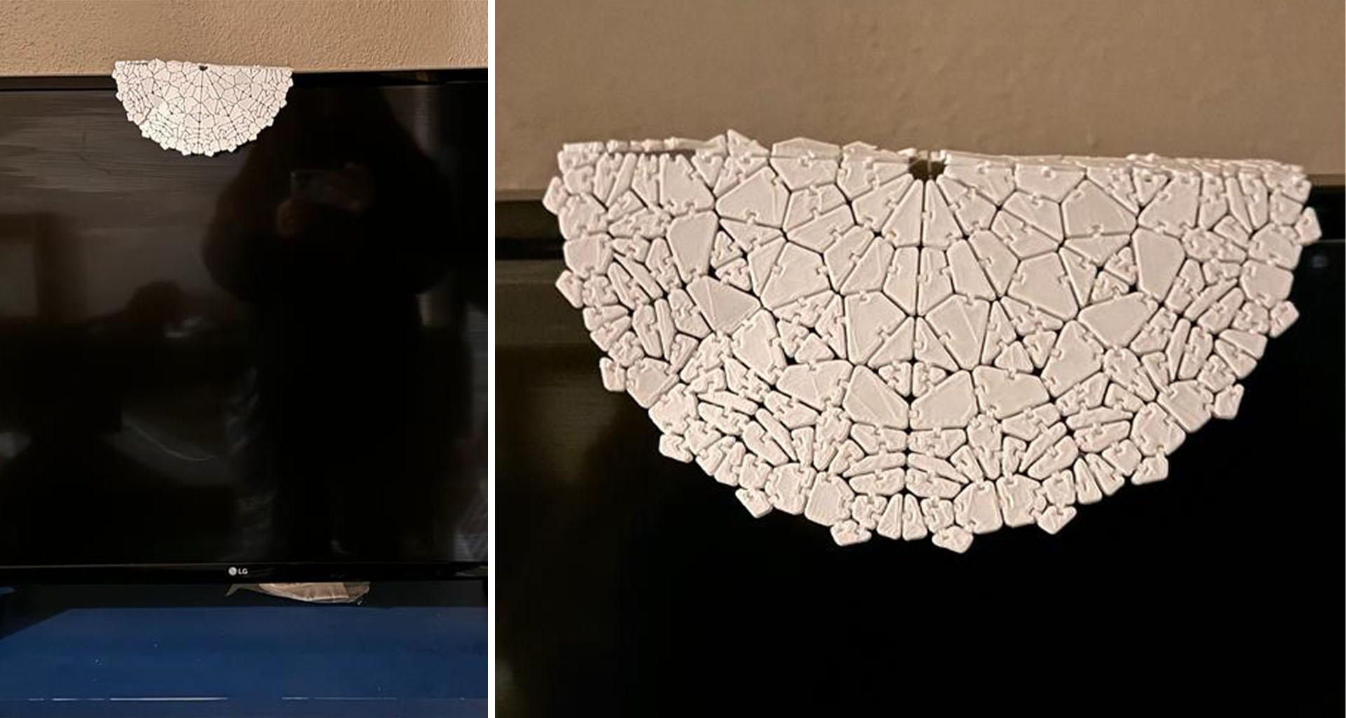
The video demonstrates that the lace pattern's main divisions are quite flexible due to the presence of joints along the lines. However, in the areas between these main divisions, flexibility is lost. This is because the joints are more dispersed and do not form a continuous, smooth pattern. As a result, these areas are prone to breaking under force, lacking the ability to stretch and absorb pressure.
Despite this, the outcome was quite impressive, especially considering the intricacy and multiple components of the design. We've displayed it above our television, reminiscent of the decor in the homes of my childhood.
Group Work
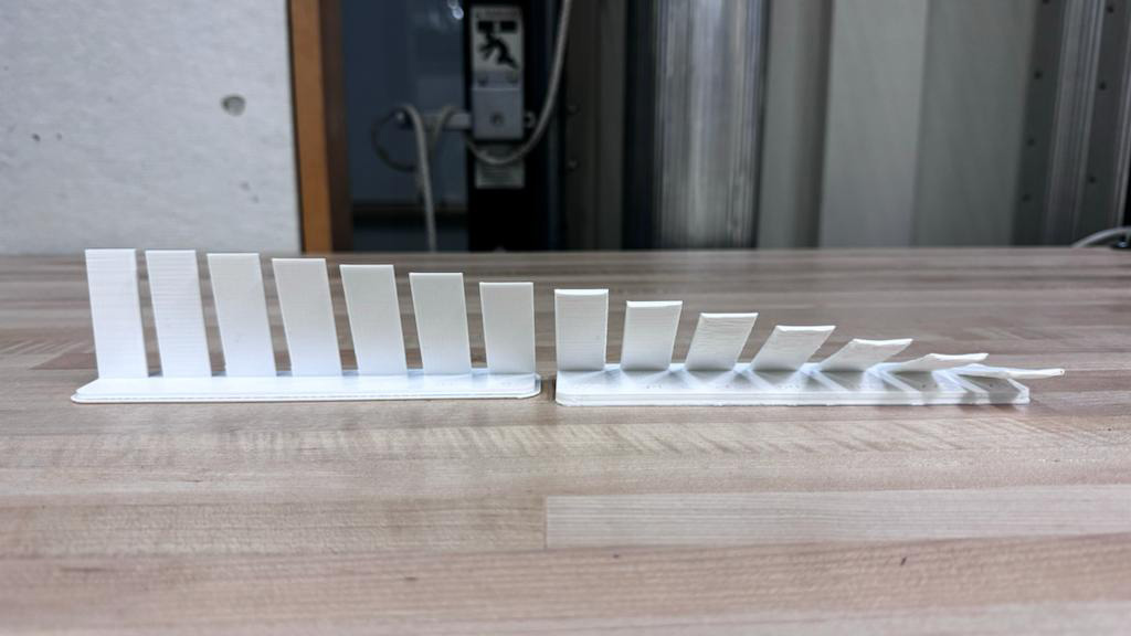
In addition to the previous trials conducted in past years, such as those involving bridges, varying thicknesses, and suspended structures, our group, consisting of Danny, Mateo, and myself, decided to explore the failure points of a straight wall during the printing process. We initiated this experiment by printing wall segments that started at a perpendicular 0-degree angle relative to the printing surface. Subsequently, we incrementally increased the angle in six-degree intervals, creating pieces that were 0.1 inch thick and 2 inches long.
Surprisingly, we found that the wall did not fail at any of the angles tested, even up to 78 degrees. However, an interesting observation emerged from our experiment. While the surface of the wall appeared very smooth at 0 degrees, as the angle increased, it became noticeably rougher, and the distinct printing layers became more apparent.