
-
Self-education, Electronics
Before tackling my assignments this week, I was taken aback by my lack of knowledge on the topics Neil covered in class about Electronics. To address this, I began by educating myself. My self-education journey commenced when I picked up a book from the library that Neil strongly recommended in class: 'Learning the Art of Electronics, A hands-on lab course' by Thomas C. Haynes with assistance from Paul Horowitz. This book is not just about theory; it's a hands-on guide from the basics to advanced topics, where you're actively building and testing circuits. I believe it's the practical, lab-based counterpart to the electronics 'bible'. Truly, it's a game-changer. Throughout the week, it remained open on my desk, assisting me whenever I needed it.


I recently stumbled upon a video on YouTube where Instructor Joe Gryniuk covered everything one would want to know about the Fundamentals of Electricity. These lectures were from his classes at Lake Washington Technical College in Kirkland, Washington. Professor Gryniuk consistently provided real-life examples to illustrate how each law or component functions, and he pointed out common mistakes people might make. I'm fortunate to have found a professor who effectively bridges the gap between theory and practice, which has been a great start for my self-education. So far, I've watched the first 11 hours of his lectures.
I consistently took notes throughout the lectures, which have been instrumental in revisiting and deepening my understanding. I've also compiled my notes into a PDF for anyone who might be interested.
https://drive.google.com/drive/folders/1hP80Qt6tPLyRfX1unlAnotwziIQnqg15?usp=sharing
Group Work, Test Equipments
Firstly, we looked at the voltage difference between the VCC input and Ground input on the breadboard system Danny prepared a few weeks ago. Additionally, we measured a resistor whose current we weren't sure about.

Subsequently, using an oscilloscope, we examined the signal produced by connecting the networking end and the ground end of the same system. We zoomed in and out on this visual to find the optimal view for our purposes. We then transferred this visual to our computer using its SSD card. The device provided us with both an image and an Excel file containing the associated values.
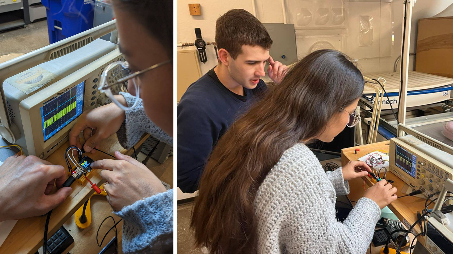

Our final test involved reading waves we generated with the Gunsteng SFG-2110 Synthesized Function Generator on the Gunsteng GDS-1152A Oscilloscope. With this experimentations, I had the opportunity to experiment with some methods the instructor, through the lecture I watched on YouTube, mentioned for debugging .

Development Boards, Exercises
I started in board development by downloading both Fusion and KiCad. Fusion seemed more complicated in terms of its libraries. Even though I downloaded the SnapEda tool, KiCad's Fablab library seemed more accessible to me. That's why I'm thinking of continuing with KiCad. Later, I followed Zach's recitation on KiCad as recommended by II Hwan Kim, a student from 2021, and reproduced what he made alongside him. It was a very good exercise for me. In fact, I tried to design places where he used Jumpers without using Jumpers, and I succeeded.


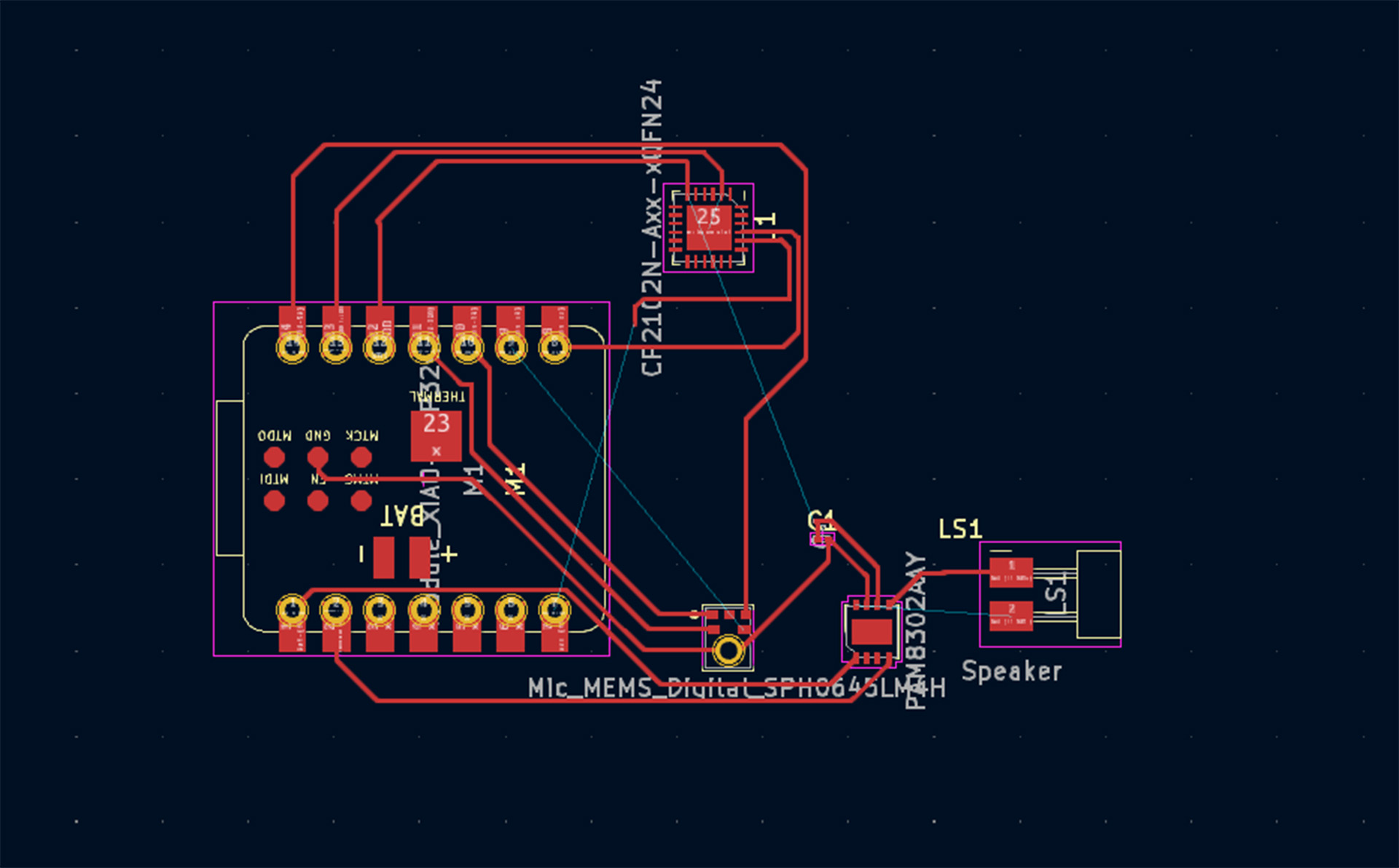
Development Boards, Designing My Own Circuit
After that, I set out to design a new development board that was more complex and could serve my final project idea in mind. During this process, I first identified the components I would need. Components: Microcontroller: ESP32-C3 with built-in Wi-Fi capabilities. USB Interface: A USB-to-serial converter for connecting the ESP32-C3 to a computer for programming and debugging purposes. Audio Input: A microphone module. Audio Output: An audio amplifier and a small speaker. Display: Waveshare 2-inch IPS LED display, which likely uses SPI for communication. Holographic Display System: The setup involving the Waveshare display, a Fresnel lens, and other optical components to create the illusion of a hologram based on the "Pepper's Ghost" theory."

After familiarizing myself with the components, I started positioning them in KiCad. Then I began creating connections between them. Here's how I routed the system:
For ESP32-C3 to USB Interface: I connected the Tx and Rx pins of the ESP32-C3 to the matching Rx and Tx pins of the USB-to-serial converter. I also linked their Ground (GND) pins.
Regarding the ESP32-C3 Wi-Fi Setup: I made use of the built-in Wi-Fi capabilities of the ESP32-C3 to connect it to a Wi-Fi network.
For ESP32-C3 to Audio Input: I connected the microphone module's output to an ADC (Analog to Digital Converter) pin on the ESP32-C3 for sound processing.
For ESP32-C3 to Audio Output: To ensure optimal sound, I used the I2S interface of the ESP32-C3 to drive the audio amplifier, which in turn powers the speaker.
For ESP32-C3 to Display: I set up an interface between the Waveshare 2-inch IPS LED and the ESP32-C3. This generally requires SPI connections like MOSI, MISO, SCLK, CS, and so on. I consulted the Waveshare documentation to get the exact pin connections and requirements.

While routing, I constantly switched between the datasheet and ChatGPT for guidance. I worked to grasp the connections between each component. However, I believe I made a few errors since the layout now seems impossible to resolve. BUT I'M UNSURE HOW TO IDENTIFY THE POTENTIAL MISTAKE I'VE MADE. This is one of my initial attempts at routing.
New Circuit Design, Motion Sensor and LEDs
Following my initial unsuccessful attempt, I opted for a simpler approach and designed a more straightforward circuit. This new design incorporates a motion sensor (HC-SR04), a single switch, and two LEDs to indicate whether the circuit is active and if someone is within a specific proximity. To construct this, I had to include an extra power source. The reason being, the motion sensor I'm using needs a 5V power input, whereas the Xiao RP2040 I'm working with only supplies 3.3V. It was so much easier to route this circuit since it was so much less complicated.

