Group Work
This week, I commenced my studies with a soldering and milling circuit training provided by Jen on Friday. In the two-hour session, Jen offered guidance as we worked on the group task to 'characterize the design rules for our in-house PCB production process'. This involved running specific trace and outline files given by Neil to evaluate the mill's settings and their effects. The file demonstrated the precision of the tracing bit (1/64) in milling intricate patterns. I found the diverse machine tests enlightening, showcasing their capabilities aspecially before starting my work.


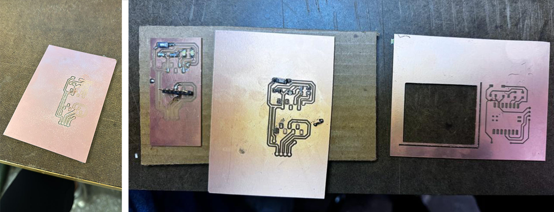
Milling and Soldering trials
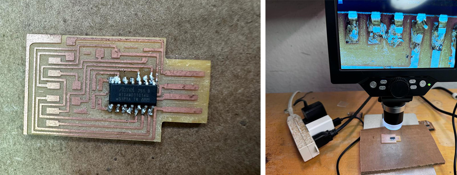
On the weekend we met with merve to work and mill our circuits together. We started to milling her circuit first. We had a lot of failures due to various reasons. For example; not giving enough attention to hight difference of the base, not putting enough tape under our board it moved from its surface once, and choosing wrong adjustments for wrong endmill. While Jen had emphasized these intricacies on Friday, we fully grasped their importance only after experiencing these setbacks firsthand. The image below illustrates the attempts Merve and I made on her circuit. Subsequently, I practiced soldering on a spare circuit provided by Jen. I quickly realized the intricacies of handling such minute components, but eventually discovered a method that worked best for me. I also examined my soldering work under a microscope, revealing details like circuit burns and overlapping solders—minute imperfections nearly invisible to the naked eye.

Breadboarding
For my own circuit, last week , electronics design, I first tried my system on breadboard. I designed the system to serve my final project. I used a Seeed Studio Xiao RP2040, HC-SR04 Ultrasonic Distance Sensor, Two Led's, Two resistors and a button. According to the fiction, if the system is on, that is, the button is 'on', one LED would turn on to emhasize the system is on. Also when the user approaches more than one meter, the distance sensor reacts and turns on the system and the second LED turns on in this case. On the other hand, a response in cm regarding the distance occurs on the serial monitor. After making sure it worked on the breadboard, I revised my circuit board on KiCad.
Here is the code I was using for this in the beginning.
    code
const int buttonPin = 2;     // Connect your button to this pin and to GND
const int ledSystemPin = 3;  // LED that indicates the system is ON
const int ledTargetPin = 4;  // LED that indicates the target is in 1 meter range
const int trigPin = 6;       // Connect HC-SR04 Trig pin to P6
const int echoPin = 7;       // Connect HC-SR04 Echo pin to P7

bool systemState = false;  // To track the button state, false is OFF and true is ON

void setup() {
  Serial.begin(9600);

  pinMode(buttonPin, INPUT_PULLUP);  // Button is active LOW
  pinMode(ledSystemPin, OUTPUT);
  pinMode(ledTargetPin, OUTPUT);
  pinMode(trigPin, OUTPUT);
  pinMode(echoPin, INPUT);
}

void loop() {
  // Check the button state
  if (digitalRead(buttonPin) == LOW) {  // If button is pressed
    delay(50);  // Debounce delay
    while (digitalRead(buttonPin) == LOW);  // Wait for button release
    delay(50);  // Debounce delay

    systemState = !systemState;  // Toggle the system state

    if (systemState) {
      digitalWrite(ledSystemPin, HIGH);  // Turn ON the system LED
    } else {
      digitalWrite(ledSystemPin, LOW);   // Turn OFF the system LED
      digitalWrite(ledTargetPin, LOW);   // Ensure target LED is OFF
    }
  }

  // If system is ON, check the sensor reading
  if (systemState) {
    long duration, distance;

    digitalWrite(trigPin, LOW);
    delayMicroseconds(2);

    digitalWrite(trigPin, HIGH);
    delayMicroseconds(10);
    digitalWrite(trigPin, LOW);

    duration = pulseIn(echoPin, HIGH);
    distance = (duration/2) / 29.1;  // Convert duration to distance in cm

    Serial.print("Distance: ");     // Print the distance
    Serial.print(distance);
    Serial.println(" cm");

    if (distance <= 100) {  // If target is within 1 meter (100 cm)
      digitalWrite(ledTargetPin, HIGH);  // Turn ON the target LED
      Serial.println("Welcome");
    } else {
      digitalWrite(ledTargetPin, LOW);   // Turn OFF the target LED
    }
  }
}


Milling, Mistakes
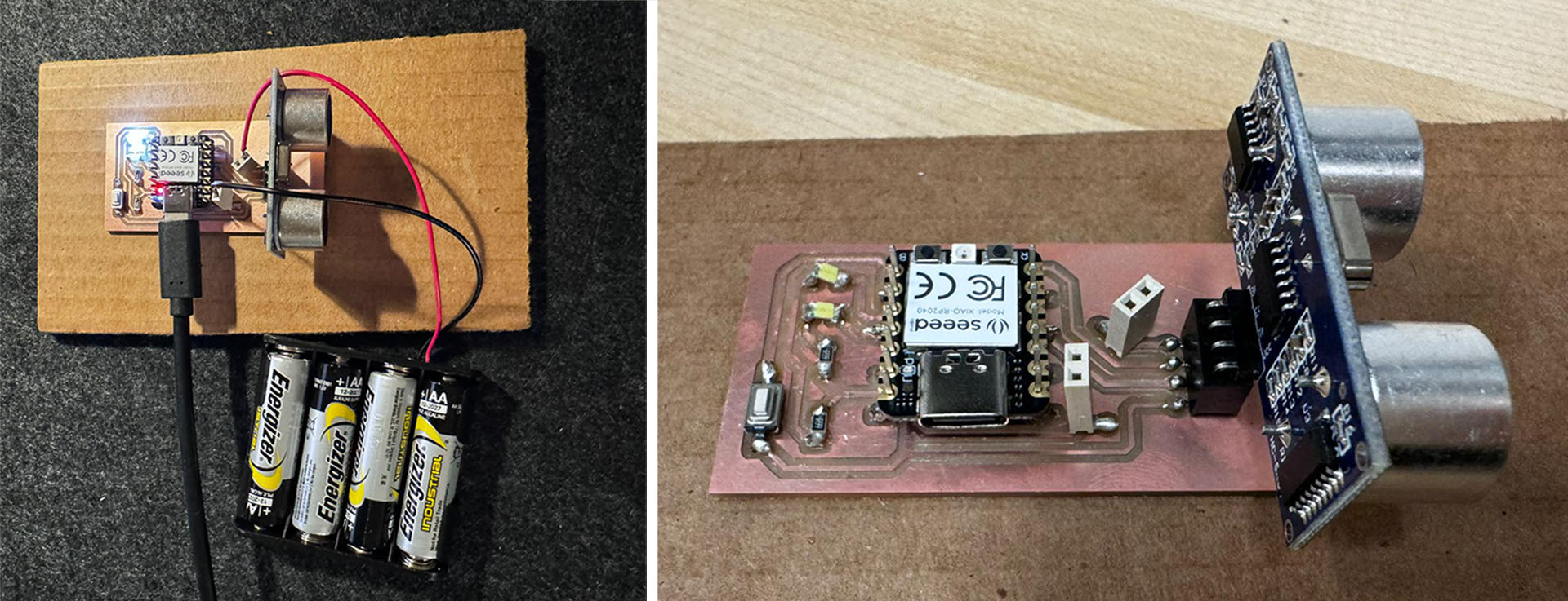
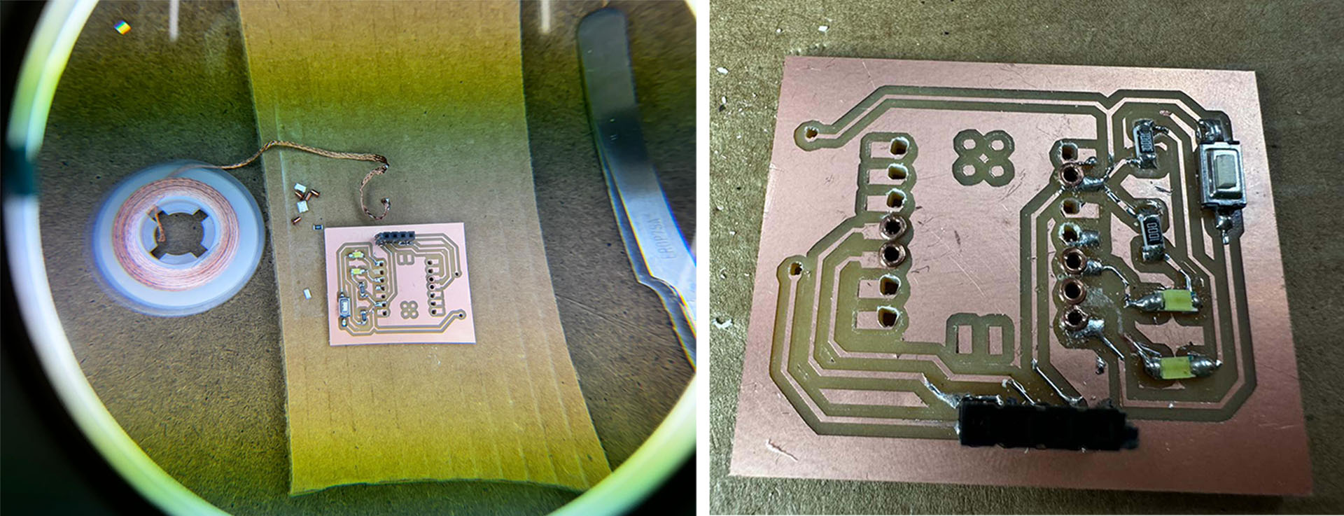
I began by customizing my board to include holes, allowing the Xiao RP2040 and HC-SR04 to be attachable and detachable, aiming for a modular system. I intended to use intermediary components for easy assembly and disassembly. On my initial attempt, I successfully milled my circuit. I utilized the 1/32 settings but with a 1/64 endmill for the milling outline, which resulted in some discrepancies in hole sizes. Some holes needed manual enlargement using the tip of a tweezer to be functional.


The real challenge arose during soldering. Initially, I managed to solder the resistor, LED, and button with ease. However, difficulties emerged when soldering a spacer designed for the HC-SR04, which had a pin on one end and a female connector on the other. The solder solidified quickly, preventing me from soldering the four parts in rapid succession, leading to incomplete connections. Subsequent testing with a multimeter revealed that while some pins conducted electricity, others didn't.
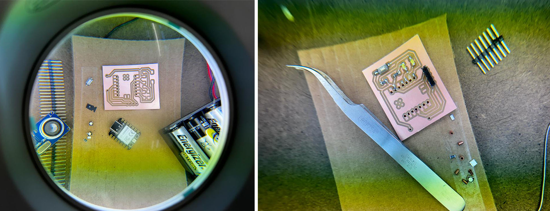
The process for the Xiao RP2040 attachment differed. To facilitate conductivity, I introduced small 1mm copper pipes at the board's connection points. Regrettably, maintaining network integrity during soldering proved challenging. Consequently, I abandoned the hole-based approach and redesigned the system in KiCad to incorporate a socket version for the Xiao RP2040.
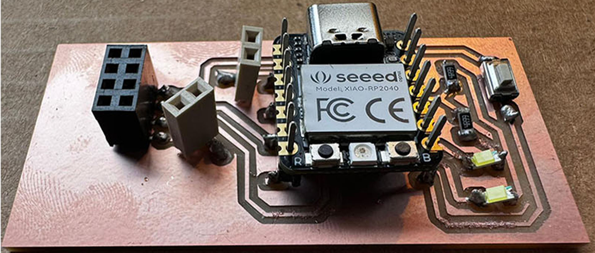
Final Circuit
I redesigned and milled my circuit one more time using socket version of the Xiao RP2040. This one went smooth and I was able to mill it in one trial.

Soldering the PCB, Do's and Dont's, Debugging
I discovered that using connectors simplified the soldering process, compared to my earlier approach of making holes. Despite successfully soldering the LEDs, they didn't produce any noise when I tested them with a multimeter by applying voltage. However, this doesn't necessarily mean that they aren't conducting electricity. This realization corrected my previous assumption and highlighted the need to consider other factors in assessing the functionality of the soldered components.


Functioning of the Curcuit
In the circuit, everything seemed normal and correctly set up, but my circuit wasn't functioning as expected. While the LEDs lit up fine, the distance sensor (HC-SR04) wasn't operational. I consulted with ChatGPT for troubleshooting advice, and it pointed out a crucial oversight regarding the power supply. I had used four 1.5 Volt batteries, which, in total, provide at least 6 Volts, potentially even more since some batteries can supply up to 1.7 Volts. This overpowered supply might have damaged the HC-SR04 sensor, as it is not designed to handle such high voltage. ChatGPT suggested that using three batteries instead of four could resolve the issue by providing a more suitable voltage level for the sensor, thereby preventing any potential damage and ensuring proper functionality.