Capacitive Touch Sensor, Trials on Breadboard
Before building a circuit, I decided to try my routing in breadboard. I successfully downloaded and installed the CapacitiveSensor Library created by Paul Badger. Following his guidelines, I constructed a circuit using 1 megaohm resistors, which I connected to the digital input and output pins of an Arduino Uno. Below is the final outcome.


Connecting Arduino IDE to MAX 8, Serial Ports.
Arduino is sending serial data to Max Msp. When the data goes above a certain number when touched, ot sends a bang.

Conductive Tread, Sewing Machine Trials
I decided to try the capacitive touch sensor, which I managed to install with 1megaohm resistors and the CapacitiveSensor library, with other conductive surfaces after fruits and plants. I also wanted to experience the effect of conductive surface amount and shape on capacitive sensor tresholds and usage. For this reason, I bought 2 capacitive threads from microcenter, the picture of which I shared below.


My plan was to create different surfaces with the sewing machine and try the signals. However, there were great difficulties in the use of this material. First of all, the thread consists of two main pieces intertwined with each other and many thin stainless steel layers underneath. These two main entangled subgroups of threads can be unwound very easily. When the metal is subjected to any load or pull, it bends immediately and does not return to its original shape. It gets tangled very quickly, is very difficult to open due to friction, and usually breaks while opening. Also, since it was not flexible like normal threads, it was impossible to sew it by machine.
At first I tried it with Singer Heavy Duty. In this experiment, I put conductive thread in both the coils above and below. It was impossible to sew. Even though I tried it on two different fabrics, the needle was only piercing the material, but the sewing process was not taking place. Even though I tried different thread holding and speed, I couldn't get any results.
Finally, I decided to manually hold the conductive threads with my hand and sew them in a gridal manner with normal thread. It was very difficult, I couldn't give it the exact shape I wanted. It also took a lot of time.
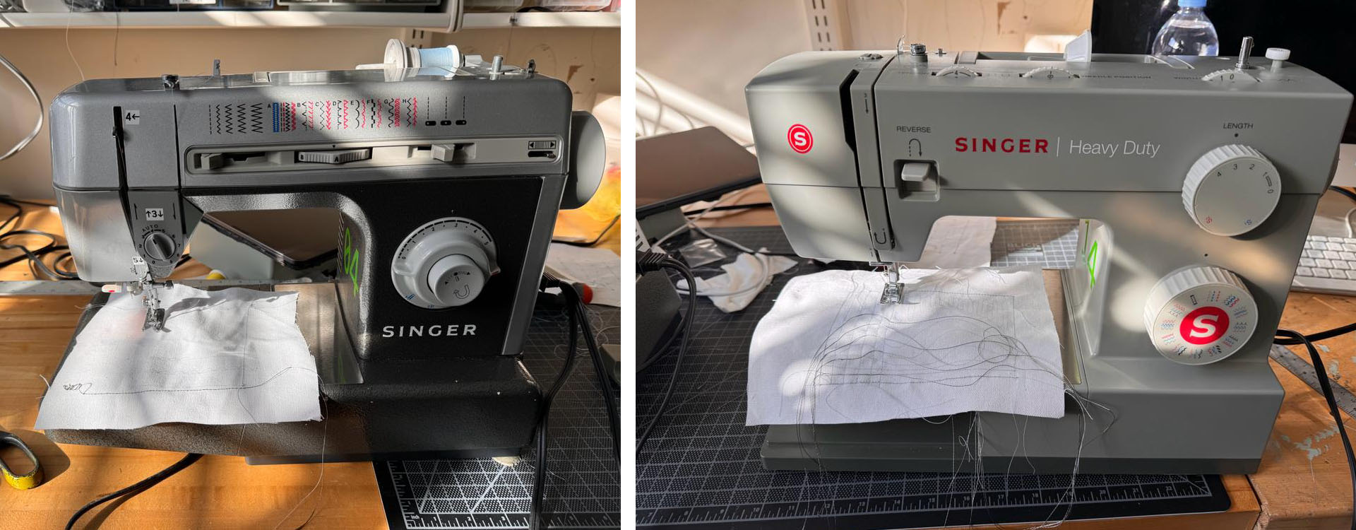

While I was working on this, Graham from Mars Lab came and suggested I switch to the other machine. The other machine I used was better suited to the bobbin under the sewing surface. While the previous machine used a straight bobbin, the curved bobbin I used worked on the second machine. Also, since my thread is thick, we also thickened the needle tip. We used the 0.28 mm needle tip. Finally, we put normal sewing thread on the upper bobbin and conductive thread on the lower bobbin. The result was truly successful. The bottom side lay flat, creating a conductive path, while the top provided a nice seam holding it in place. However, if I did not sew a straight line in these attempts, the thread felt thick and would split immediately. After 4 hours spent in front of the sewing machine, I accepted that it was not possible to give the shapes and curves I wanted with this material, and with many failure mock ups in hand.
Trying Other Microcontrollers, Xiao RP2040, Xiao ESP32 C3, Raspberry Pi Pico, Raspberry Pi Zero W, Arduino Nano 3.0

Conductive Tread and Electronic Embroidery
I thought of the embroidery kit I have at home. I was going to create the conductive surfaces I dreamed of by sewing them with my hands. My plan was to create an embroidery with an undersea concept, add LEDs to the animals' eyes, and hear the sounds I assigned in MAX8 along with the LEDs that light up when I touch the animals. However, unfortunately, hand sewing was not possible with this thread. The material constantly broke off and was constantly tangled. I had to cut short ropes, constantly renew the rope and patch the previous one.
But still, in the end my mock'up worked. I created the circuit with Thread and connected it. Although the system worked, there were some inconsistencies. Thinking that it was related to the conductive wires overlapping each other and touching the microcontroller from different places, I decided to make the connections of the circuit with plastic-coated solid wires. But as soon as I used wires my system stopped working. Even though there was no disconnection anywhere when I measured it with a multimeter and I installed the same system as I had previously set up on the breadboard, somehow my system did not work. I DO NOT UNDERSTAND WHY.
**After discussing the issue with Antony, he recommended that I solder the circuit wires. He suspects that the problem could be due to the wires being loose.


Capacitive Sensor PCB Design
After examining so many different capacitive sensors, I found out that there are two common approaches for designing a capacitive touch sensor circuit to interface with a microcontroller.
METHOD 1: CAPACITIVE SURFACE TO ANALOG PIN WITH GROUNDED RESISTOR
In this method, each capacitive touch pad is directly connected to an analog input pin of the microcontroller. A high-value resistor (like 1MΩ) is connected between each touch pad and the ground.When a finger touches the pad, it changes the capacitance between the pad and ground. The microcontroller measures this change in capacitance indirectly by measuring the voltage at the analog pin, which changes due to the variation in capacitance. This method is simpler and more direct. It is easier to implement, especially with microcontrollers that have multiple analog input pins. It may be less sensitive or slower to respond, as the capacitance change is measured indirectly through voltage changes.
METHOD 2: CAPACITIVE SURFACE TO INPUT PIN, WITH RESISTOR LINKED TO OUTPUT PIN
Each capacitive pad is connected to a digital I/O pin configured as an input. Another pin, configured as an output, is connected to the same touch pad through a 1MΩ resistor. The output pin charges the capacitive pad through the resistor, and then the pin is switched to input mode. The microcontroller measures the time it takes for the voltage at the pad (now an input) to discharge through the capacitance of the pad, which changes when touched. This method can be more sensitive and quicker to respond. It directly measures the discharge time, which is a more accurate indicator of capacitance changes. It can be more complex to implement, as it requires precise timing measurements and control over the I/O pins. It also uses more pins on the microcontroller.


Milling and Soldering
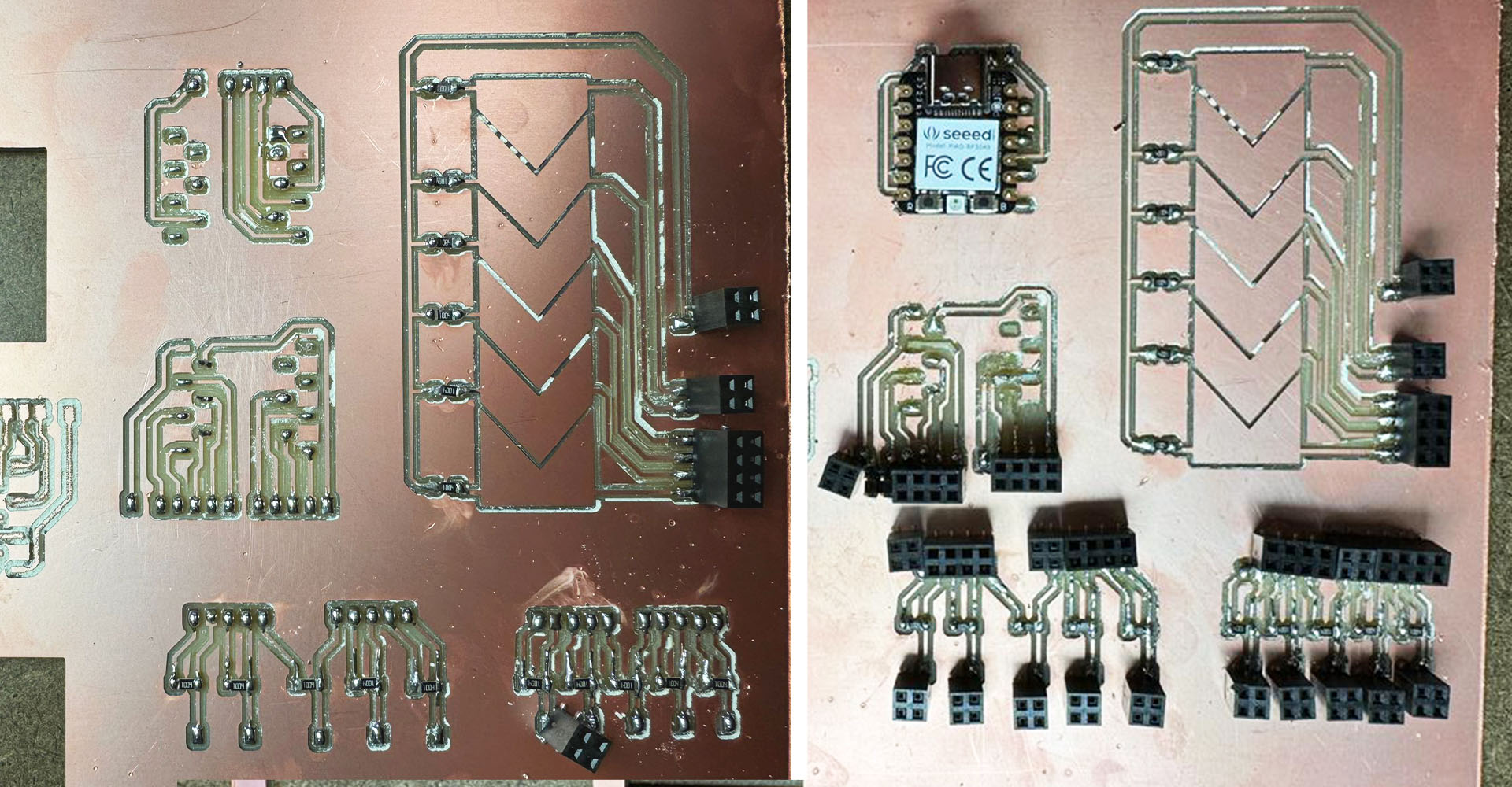
I opted to mill a slider using Method 1 along with two Method 2 capacitive touch circuits. The milling process for the routing was successful, but issues arose when the machine started to trim the edges. The copper board separated from the base, causing the circuit to become unstable. After two unsuccessful attempts, I chose not to trim the edges to maintain their integrity. This decision was partly due to significant damage to the base and also because the endmill was not in optimal condition.

How it works
You can see the results here: the capacitive sensor worked as expected. Notably, Method 2 provided a more sensitive output than Method 1. However, I'm unsure why one of the pads inside my slider consistently shows a lesser response even thoug everything was the same. The reason may be the soldering quality. But slider still works.
METHOD 2, Capacitive Sensor Arduino IDE code.
#include

// Define the send and receive pins
// Example: pin 4 is the send pin, and pin 2 is the sensor pin (connected to your copper PCB)
CapacitiveSensor capSensor = CapacitiveSensor(4,2);

void setup() {
    // Start serial communication
    Serial.begin(9600);

    // Optional: for increased sensitivity
    capSensor.set_CS_AutocaL_Millis(0xFFFFFFFF);
}

void loop() {
    // Read the value from the capacitive sensor
    long sensorValue = capSensor.capacitiveSensor(30);

    // Print the value to the Serial Plotter
    Serial.println(sensorValue);

    // Small delay to avoid overwhelming the serial plotter
    delay(100);
}
METHOD 1, Capacitive Slider Arduino IDE code
const int numSensors = 6;  // Number of sensors
const int sensorPins[numSensors] = {A0, A1, A2, A3, A4, A5}; // Sensor pins
int sensorValues[numSensors]; // To store sensor values

void setup() {
    Serial.begin(9600);
    // Initialize sensor pins
    for (int i = 0; i < numSensors; i++) {
        pinMode(sensorPins[i], INPUT);
    }
}

void loop() {
    // Read each sensor
    for (int i = 0; i < numSensors; i++) {
        sensorValues[i] = analogRead(sensorPins[i]);
    }

    // Send values in a single line separated by spaces
    for (int i = 0; i < numSensors; i++) {
        Serial.print(sensorValues[i]);
        if (i < numSensors - 1) {
            Serial.print(" "); // Separate values with a space
        }
    }
    Serial.println(); // End of a set of readings

    delay(100); // Short delay for readability
}
Processing Vode for Visualising the Method 1, Capacitive Slider.
import processing.serial.*;

Serial myPort;  // The serial port
String val;     // Data received from the serial port
int[] sensorValues = new int[6];
int sliderWidth;

void setup() {
  size(600, 200);
  println("Available serial ports:");
  String[] ports = Serial.list();
  for (int i = 0; i < ports.length; i++) {
    println(i + ": " + ports[i]);
  }

  // Replace this index with the index of COM5
  int com5Index = findComPortIndex("COM5", ports);
  if(com5Index != -1) {
    myPort = new Serial(this, ports[com5Index], 9600);
    println("Connecting to " + ports[com5Index]);
  } else {
    println("COM5 not found. Check your connections and port name.");
    exit(); // Exit the program if COM5 is not found
  }

  sliderWidth = width / sensorValues.length;
}

void draw() {
  while (myPort.available() > 0) {
    val = myPort.readStringUntil('\n');
    if (val != null) {
      val = trim(val);
      String[] stringValues = split(val, ' ');
      if (stringValues.length == sensorValues.length) {
        for (int i = 0; i < sensorValues.length; i++) {
          sensorValues[i] = int(stringValues[i]);
        }
      }
    }
  }

  background(255);
  for (int i = 0; i < sensorValues.length; i++) {
    // Adjust the mapping here
    int lowerBound = 0; // Adjust based on your sensor's minimum value
    int upperBound =250; // Adjust based on your sensor's maximum value
    int colorIntensity = int(map(sensorValues[i], lowerBound, upperBound, 0, 255));
    fill(0, 0, colorIntensity, 150);
    rect(i * sliderWidth, 0, sliderWidth, height);

    fill(255, 0, 0, 150);
    rect(i * sliderWidth, 0, sliderWidth, height - int(map(colorIntensity, 0, 255, 0, height)));
  }
}

// Function to find the index of the COM port
int findComPortIndex(String comPort, String[] ports) {
  for (int i = 0; i < ports.length; i++) {
    if (ports[i].equals(comPort)) {
      return i;
    }
  }
  return -1; // Return -1 if not found
}
Group Work
Working with Niklas Hagemann, we attemped to use the oscilloscope to visualize analog input. After wiring setup of the capacitive sensor, the signal displayed on the oscilloscope corresponds to the compression of the capacitive accordion.
