go home
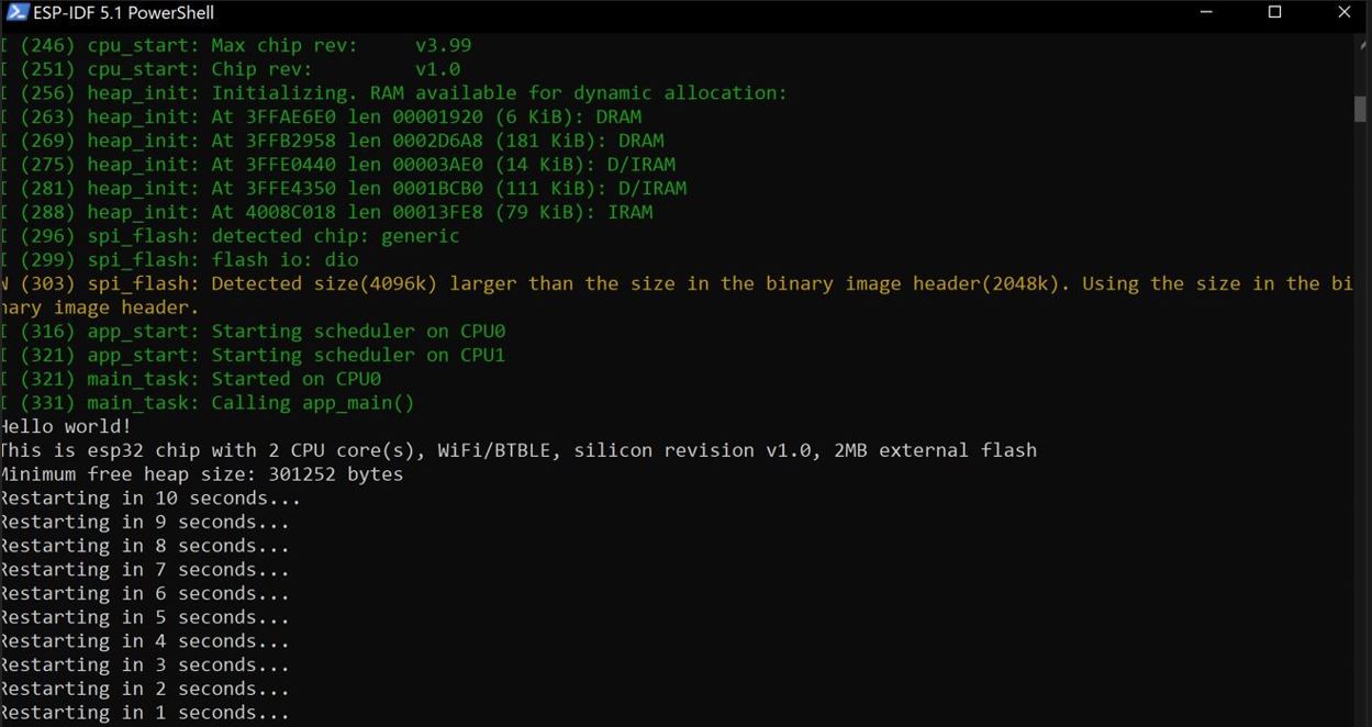
$ idf.py fullclean
// you clean build folder if needed
$ idf.py build
// in the fodler w CMakeLists.txt
$ idf.py -p COM9 flash
// flash it
$ idf.py -p COM9 monitor
 I suppose that that connection was unstable. I frist wanted to see if the screen was broken so I
went to office hours to see if a TA knew where I could get another TFT LCD screen.
I showed Quinten the screen as it was and he asked why I wasn't using the LED pin and I thought that the LED
pin was just for an LED blinky light for debugging, and I couldn't physically get the trace anywhere, I wouldnt have to
connect it via jumper cable anyways, or have it go on the back of the board.
We looked at the spec and it was the back light for the screen!
It made me confused how it worked at all in the frist place? Maybe pressing down hard on it made it so some light got though in the cracks?
I am not sure.
I suppose that that connection was unstable. I frist wanted to see if the screen was broken so I
went to office hours to see if a TA knew where I could get another TFT LCD screen.
I showed Quinten the screen as it was and he asked why I wasn't using the LED pin and I thought that the LED
pin was just for an LED blinky light for debugging, and I couldn't physically get the trace anywhere, I wouldnt have to
connect it via jumper cable anyways, or have it go on the back of the board.
We looked at the spec and it was the back light for the screen!
It made me confused how it worked at all in the frist place? Maybe pressing down hard on it made it so some light got though in the cracks?
I am not sure.


#include#include #include #include #include "Adafruit_ILI9341.h" //#include #include // JPEG decoder library //#include #include "esp_camera.h" #include "camera_index.h" #include "Arduino.h" // #include "fd_forward.h" #include // #include // TFT_eSPI tft = TFT_eSPI(); // #include AsyncWebServer webserver(80); AsyncWebSocket ws("/ws"); // const char* ssid = "NSA"; // const char* password = "orange"; const char* ssid = "MIT"; const char* password = "]BnPcs9765"; String filelist; camera_fb_t * fb = NULL; String incoming; long current_millis; long last_capture_millis = 0; static esp_err_t cam_err; static esp_err_t card_err; char strftime_buf[64]; long file_number = 0; //copy pasting from other file // #define PIN_NUM_MISO 13 // #define PIN_NUM_MOSI 12 // #define PIN_NUM_CLK 14 // #define PIN_NUM_CS 15 // #define PIN_NUM_DC 2 // #define PIN_NUM_RST 4 #define TFT_DC 2 #define TFT_CS 15 #define TFT_MOSI 12 #define TFT_CLK 14 #define TFT_RST 4 #define TFT_MISO 13 //Adafruit_ILI9341 tft = Adafruit_ILI9341(TFT_CS, TFT_DC); //Adafruit_ILI9341 tft(TFT_CS, TFT_DC, TFT_RST); Adafruit_ILI9341 tft = Adafruit_ILI9341(TFT_CS, TFT_DC, TFT_MOSI, TFT_CLK, TFT_RST, TFT_MISO); //TFT_eFEX fex = TFT_eFEX(&tft); // CAMERA_MODEL_AI_THINKER #define PWDN_GPIO_NUM 32 #define RESET_GPIO_NUM 4 #define XCLK_GPIO_NUM 0 #define SIOD_GPIO_NUM 26 #define SIOC_GPIO_NUM 27 #define Y9_GPIO_NUM 35 #define Y8_GPIO_NUM 34 #define Y7_GPIO_NUM 39 #define Y6_GPIO_NUM 36 #define Y5_GPIO_NUM 21 #define Y4_GPIO_NUM 19 #define Y3_GPIO_NUM 18 #define Y2_GPIO_NUM 5 #define VSYNC_GPIO_NUM 25 #define HREF_GPIO_NUM 23 #define PCLK_GPIO_NUM 22 void setup() { Serial.begin(115200); pinMode(4, OUTPUT);// initialize io4 as an output for LED flash. digitalWrite(13, LOW); // flash off/ //init_wifi(); tft.begin(); tft.setRotation(3); // 0 & 2 Portrait. 1 & 3 landscape tft.fillScreen(0); tft.setCursor(35,55); tft.setTextColor(0); tft.setTextSize(1); tft.println(WiFi.localIP()); delay(5000); camera_config_t config; config.ledc_channel = LEDC_CHANNEL_0; config.ledc_timer = LEDC_TIMER_0; config.pin_d0 = Y2_GPIO_NUM; config.pin_d1 = Y3_GPIO_NUM; config.pin_d2 = Y4_GPIO_NUM; config.pin_d3 = Y5_GPIO_NUM; config.pin_d4 = Y6_GPIO_NUM; config.pin_d5 = Y7_GPIO_NUM; config.pin_d6 = Y8_GPIO_NUM; config.pin_d7 = Y9_GPIO_NUM; config.pin_xclk = XCLK_GPIO_NUM; config.pin_pclk = PCLK_GPIO_NUM; config.pin_vsync = VSYNC_GPIO_NUM; config.pin_href = HREF_GPIO_NUM; config.pin_sscb_sda = SIOD_GPIO_NUM; config.pin_sscb_scl = SIOC_GPIO_NUM; config.pin_pwdn = PWDN_GPIO_NUM; config.pin_reset = RESET_GPIO_NUM; config.xclk_freq_hz = 20000000; config.pixel_format = PIXFORMAT_JPEG; config.frame_size = FRAMESIZE_QVGA;//FRAMESIZE_QVGA; config.fb_count = 1; //config.pixel_format = PIXFORMAT_JPEG; //init with high specs to pre-allocate larger buffers // camera init cam_err = esp_camera_init(&config); if (cam_err != ESP_OK) { Serial.printf("Camera init failed with error 0x%x", cam_err); return; } sensor_t * s = esp_camera_sensor_get(); s->set_framesize(s, FRAMESIZE_QQVGA); s->set_vflip(s, 1); } void onEvent(AsyncWebSocket * server, AsyncWebSocketClient * client, AwsEventType type, void * arg, uint8_t *data, size_t len) { // String incoming = String((char *)data); No idea why.. gave extra characters in data for short names. // so .... for (size_t i = 0; i < len; i++) { incoming += (char)(data[i]); } Serial.println(incoming); } void loop() { int xpos = 0; int ypos = 0; fb = esp_camera_fb_get(); //TJpgDec.drawJpg(0, 0, (const uint8_t*)fb->buf, fb->len); //tft.writePixels((uint16_t*)fb->buf, (uint32_t)fb->len, true, false); Serial.println("len"); Serial.println((uint32_t)fb->len); JpegDec.decodeArray((uint8_t*)fb->buf, (uint32_t)fb->len); uint16_t *pImg; uint16_t mcu_w = JpegDec.MCUWidth; uint16_t mcu_h = JpegDec.MCUHeight; uint32_t max_x = JpegDec.width; uint32_t max_y = JpegDec.height; // Jpeg images are draw as a set of image block (tiles) called Minimum Coding Units (MCUs) // Typically these MCUs are 16x16 pixel blocks // Determine the width and height of the right and bottom edge image blocks uint32_t min_w = max_x % mcu_w;//min(mcu_w, ); uint32_t min_h = max_y % mcu_h;//min(mcu_h, ); // save the current image block size uint32_t win_w = mcu_w; uint32_t win_h = mcu_h; // record the current time so we can measure how long it takes to draw an image uint32_t drawTime = millis(); // save the coordinate of the right and bottom edges to assist image cropping // to the screen size max_x += xpos; max_y += ypos; char str[100]; // read each MCU block until there are no more while ( JpegDec.read()) { // save a pointer to the image block pImg = JpegDec.pImage; // calculate where the image block should be drawn on the screen int mcu_x = JpegDec.MCUx * mcu_w + xpos; int mcu_y = JpegDec.MCUy * mcu_h + ypos; // check if the image block size needs to be changed for the right and bottom edges if (mcu_x + mcu_w <= max_x) win_w = mcu_w; else win_w = min_w; if (mcu_y + mcu_h <= max_y) win_h = mcu_h; else win_h = min_h; // calculate how many pixels must be drawn uint32_t mcu_pixels = win_w * win_h; // draw image block if it will fit on the screen if ( ( mcu_x + win_w) <= tft.width() && ( mcu_y + win_h) <= tft.height()) { // open a window onto the screen to paint the pixels into //TFTscreen.setAddrWindow(mcu_x, mcu_y, mcu_x + win_w - 1, mcu_y + win_h - 1); //TFTscreen.setAddrWindow(mcu_x, mcu_y, mcu_x + win_w - 1, mcu_y + win_h - 1); // push all the image block pixels to the screen //////////////////////////////////////////////////////// while (mcu_pixels--) { tft.pushColor(*pImg++); } // Send to TFT 16 bits at a time //////////////////////////////////////////////////////// // Write all MCU pixels to the TFT window for (int jj=mcu_y;jj = tft.height()) JpegDec.abort(); } // calculate how long it took to draw the image drawTime = millis() - drawTime; // Calculate the time it took // print the results to the serial port Serial.print ("Total render time was : "); Serial.print(drawTime); Serial.println(" ms"); Serial.println("====================================="); ///fex.drawJpg((const uint8_t*)fb->buf, fb->len, 0, 6); esp_camera_fb_return(fb); fb = NULL; delay(4000); // // } }