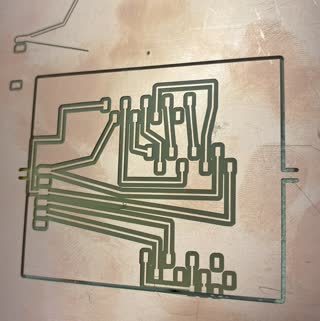
This is what I started working with:

I made this in Leo's pcb svg. you can see the code in week 5 page.
There is a lot wrong with is, Lingdong helped me see how messed up it was.
a big thing was that I wouldn't want to solder that programmer FT23RL myself.
There was also a lot of wires that were too close, this also didnt account for where the SD card slides in.
I also realized that I didn't want to make a streaming DJ USB anymore.
My next idea was more inspired by my unfeasible final project. If I wanted to make a hardware FFT I would need to make a sin wave in hardware. I broke down the problem I was faced with and thought that a good first step and also a failsafe if I get disenchanted by my final project idea was to make a cheap small digital art display that would manipulate pixels from a live camera feed using hardware transformations.
So, for example I would apply a transform on the pixels as a function to their XY position plus time to displace the pixels on the screen and show that on the LCD screen.
But before that I would need to just be able to get camera in and LCD out. So that is what I set out to do.
Honestly it took me too long to come up with what I wanted to do.
Anyways, I got the ESP32-CAM
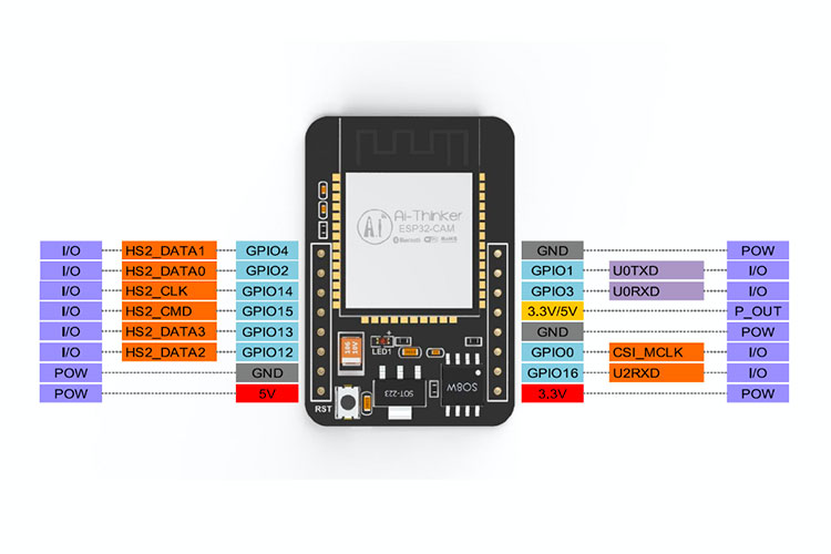
This comes with camera.
I sourced my components... I didn't realize the lab had everything.
I used iphone AR to measure the components so I could get the size of the board right.
since the footprints didnt take in account the overhang of the components.

this is me sketching out the layout between the TFT LCD screen and my ESP32CAM. I was sure that I would need a jump but turned out I didnt! I just couldnt connect the screen LED to anything :(

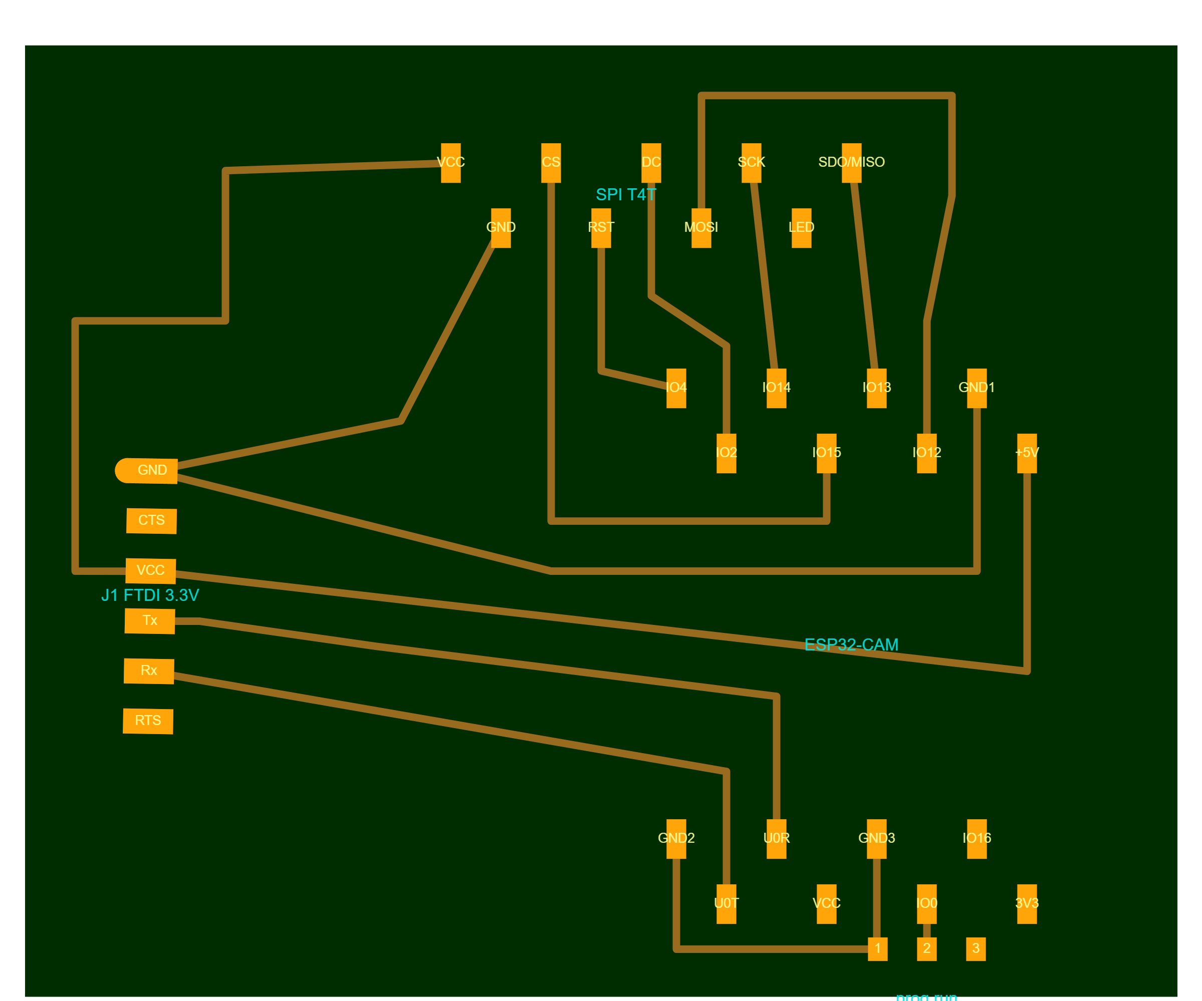
again using pcb svg I designed a new board.
I couldnt find the right footprint for my screen on www.snapeda.com, so I wrote my own using another screen footprint as a base. It was fun but a little time consuming to get it right.
This is the only documentation I have of my
code for this. I accidentally navigated away after i downloaded the image (and kicad)
and when I went back the local storage was an earlier version of the board.
I tried to see if I could traverse to older versions of local storage but I couldn't.

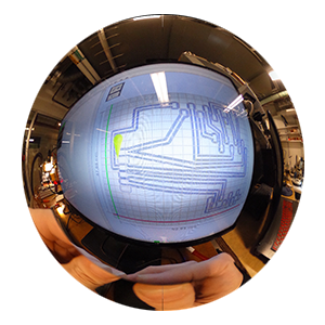
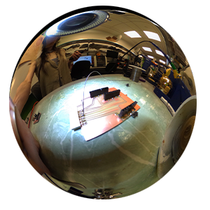
This is the final board I made:
First I used https://quentinbolsee.pages.cba.mit.edu/gerber2img/ to create a black and white image of my board from the downloaded kicad file

Then, I used https://modsproject.org/ mill 2D to generate the gcode.
I broke 2 bits because I didn't realize the connection that allows the z zero macro to work was broken even if it was connected. Then Wedyan and Vincy fixed it!

This is the board all cut out! You can see the mis-starts in wrong positions in the top left.
I tested all the connections with a multimeter and it was all good!
I had a blast soldering. I went to Cyrus lab & It was fun being around the electrical engineers, they know all these fun little tricks.
I followed many different tutorials,
this was one of them
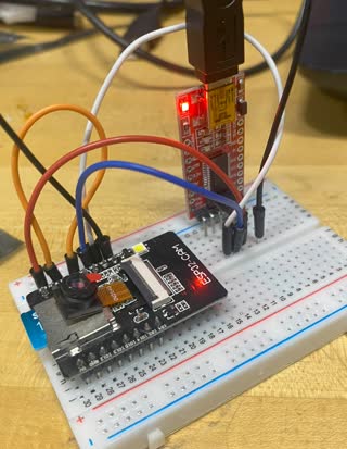
I put it all together but I was getting error that there was "A fatal error occurred: Failed to connect to ESP32: No serial data received" error
I tried many different configurations to figure it out...
I put together a breadboard to see if I could get it to work there,
it was able to upload the code at that point but then the page
that was supposed to be streaming the camera had an error.
I was out of time to finish debugging.
key takeaways
This week I had the most challenges and wasn't able to produce a working end piece, I think it was because I started a different new project instead of building
on the last weeks. It was necessary beacuse I like this idea more and I think I will continue to work on it.
I spent a lot of time this week thinking about what I wanted to do for my final prject. I think I landed on something.