## Making a boat
I have been working towards making a boat. My initial idea was to make a Laser Sailboat. Here is my rough sketch:

Upon doing some research on previous boat builds and scrolling through endless forums and subreddits, I determined that making a Laser or explicitly using Laser dimensions to make a boat is illegal (woops!). Also that curving wood plywood requires a steamer, which I did not have access to in the Mars Lab.
With more research, I determined that a good first boat to attempt would be the oz gooze. Albeit a little ugly, it satisfies the criteria that it is a medium sized dinghy which can seat 2-4 (if you are feeling ambitious), has no curved sides and can be held together with duct tape and cable ties before using epoxy - which means it is relatively more stable!
Here is the final [1-slide presentation](https://docs.google.com/presentation/d/1gjdXO7-3lmSD-oS45zstkJaB1mBJQ8_KF6qCkntkX3g/edit?usp=sharing) of the project:

### Electronics on the boat
*A big shoutout to Alan for this part! He helped troubleshoot a lot of issues with lack of 1/64 endmills and even wrote a new workflow in mods so we could use the v-bits without any issues. Whats more, he hung out by the E15 electronics room so he could troubleshoot any issues and clarify any doubts, all while finishing his own final assignment!*
Okay, so the plan is to add sensors on the boat that measure the direction of wind on a sailboat, the gps coordinates and speed of the boat using an [anomometer shaped like a wind vane](https://www.amazon.com/Anemometer%EF%BC%8CWind-Transmitter-Transducer-Anemometer-Instruments/dp/B0851DF842) and the ([GT-U7](https://www.amazon.com/Navigation-Satellite-Compatible-Microcontroller-Geekstory/dp/B07PRGBLX7)) GT-U7.
During the input and output weeks I have successfully read and calibrated the anemometer (purchased for $40) and displayed that information on an oled display (go to that [page](../week_9/output_devices.html))
The video shows me reading from the anemometer:
For the final project,
(11/13): I need to mill the pcb board and provide a nice casing to water proof the circuit in my boat.
#### Designing the pcb
The PCB design was relatively simple. I stuck to a pico w micro-controller because I wanted to leave the optionality of adding in more sensors for future spirals (like this [sparkfun weather kit](https://learn.sparkfun.com/tutorials/weather-meter-hookup-guide/all) and radar/ultrasonic sensors for sensing obstacles nearby, etc). Also, I had used the pico w during input and output weeks, and proceeded with using a pico w, in the interest of time, but a ESP32C3 xaio microcontroller could also work for the functionality.
Here is my kicad electronic design which incorporates all the following elements:
1. Raspberry Pi Pico W microcontroller
2. Through holes for the GPS module GT-U7
3. (2x) 1x4 verticle 2.54 mm Surface mount connectors for Oled display
4. and Wind Vane.
**EDA**
Unlike a bread board set-up where you can completely ignore routing traces on a one-sided PCB board, I had to addtionally add a 0 Ohm resistor to make sure my routing worked.
**Milling**
Now coming to the milling - of course there were iterations here ...
1. Due to the uneven copper stock and bed, my first mill did not cut completely through, even after pausing and re-adjusting my z coordinates manually to make the cut deeper. After retrying once, I realized that despite attaching and the copper stock to an acrylic plate, the bed was uneven because the sacrificial board in the bottom had been cut through.
There were marks even on the acrylic plate(!) indicating that students had cut through two copper boards and acrylic using 1/64 or 1/32 endmill! Perhaps that explains some of the long line of broken endmills.
2. After replacing the two copper boards and turing the acrylic upside down (to the unsracted side), I retried my milling. This time it worked, however, I did have to re-mill again because the edge cuts and through-holes did not align with the traces.
Uploading all my gerber files containing edge cuts, traces and through holes altogether in gerber2image utility that Quentin provided worked well. However, when uploading them individually, i.e, first traces, then eddge cuts + through holes led some bug with the edge cuts line running off the board (not forming a closed vector). I was making sure to click the lock origin button on the origin, however, the edge cuts seem to not fit in the parameters.
**Neat trick for aligning traces and other cuts (edges, through holes, etc) with gerber2image and a 2d paint program**
Alan helped me with this trick.
1. I generated 2 png files with gerber2image: first with all the traces, edges and through holes and second with just the traces for my cicuit that were already milled.
2. Then I uploaded these images into a 2d paint program (in my case adobe Illustrator) and lined these up these images in separate layers. Reducing the opacity of one image and lining it up with the other makes sure you can see both the images and ensure that the traces are the same size. This is expected, however, it was good to double check, since the origins of the two images were different.
3. Then finally, I subtracted the (x1, y1) origin values of the image with the higher origin coordinates from those that were lower (x0, y0) to get the desired offset.
This seems very intuitive after the fact, but, it saves so much time and makes sure that the through holes line up with the traces perfectly that I believe we can just add it as a check in case any of the previous steps offsets the origin.
Previously milled boards:
Now to the beautifully milled board!
Since I did the milling with v-bit, I had to go in with an exacto knife to finish the board.
**Soldering**
I soldered all the pico W and verticle connectors on the pcb.
Here is a video (which is oddly calming) of me soldering my compenents on the pcb.
After I soldering the connectors, I realized my first mistake:
I flipped the orientation of the gps module and now it did not fit on the PCB, alas! I had originally planned to have the gps module soldered directly on the board, but now I had to make the ugly fix of soldering header pins from under the board and solder another set of pins to gps module and connect them with the female-female wires.
Moving on, I completed my board and connected all the components and tested all connections them with a multimeter.

Since this was a new pico, I had to reboot and flash the pico w with latest firmware and after a surprising about of debugging, I got my previous code to read wind readings and displayed on an oled display. (Lesson here was: Never take anything you did previously for granted and test all your work with a new pcb and microcontroller).
Another interesting observation was that in new pico w board setup analog output of the wind vane was ~ 3 V, unlike previously where the analog output was ~3.1 V. Calibrating this was important so I dont get any non-sensical values like 0-370 degrees for example.
Ok! so we have the electronics, but we can't carry that on a boat just as is. We need a casing!
**Electronics Casing**
I am surprised how quickly this came together! I was initially planning to 3D print a box in PLA but I did not like the asthetic of that with my boat. Plus, I am not sure how water tight that can be.
I was also interested in making something modular (that can be removed and placed in another boat for example).
I neglected Laser cutting a box as an option until I saw fellow students (Daniel and Char) working on their own electronics box with wood. It immediately struck me that I could do the same and it will look a whole lot better!
I quickly designed an electronics box (this was surprisingly quick to CAD for me, especially as I am still a n00b when it comes to Fusion).
*CAD Side note: After this class, I plan to spend some time testing Rhino, Grasshopper etc. and getting good at this skill because it seems very important, however, I still struggle with a lot of basic questions in CAD in Fusion like "what is a good way to create a curved surface passing through a set of points and having a curve angle x". When I figure something out, it's usually after hours of trial and error and hard for me recreate. Its both a fun and frustrating process.*
I then cut some scrap wood I found in the lab to make the box!
[Placeholder for the CAD files since I do not have access to them now!]
Here is the final look!

**Final Video of electronics**
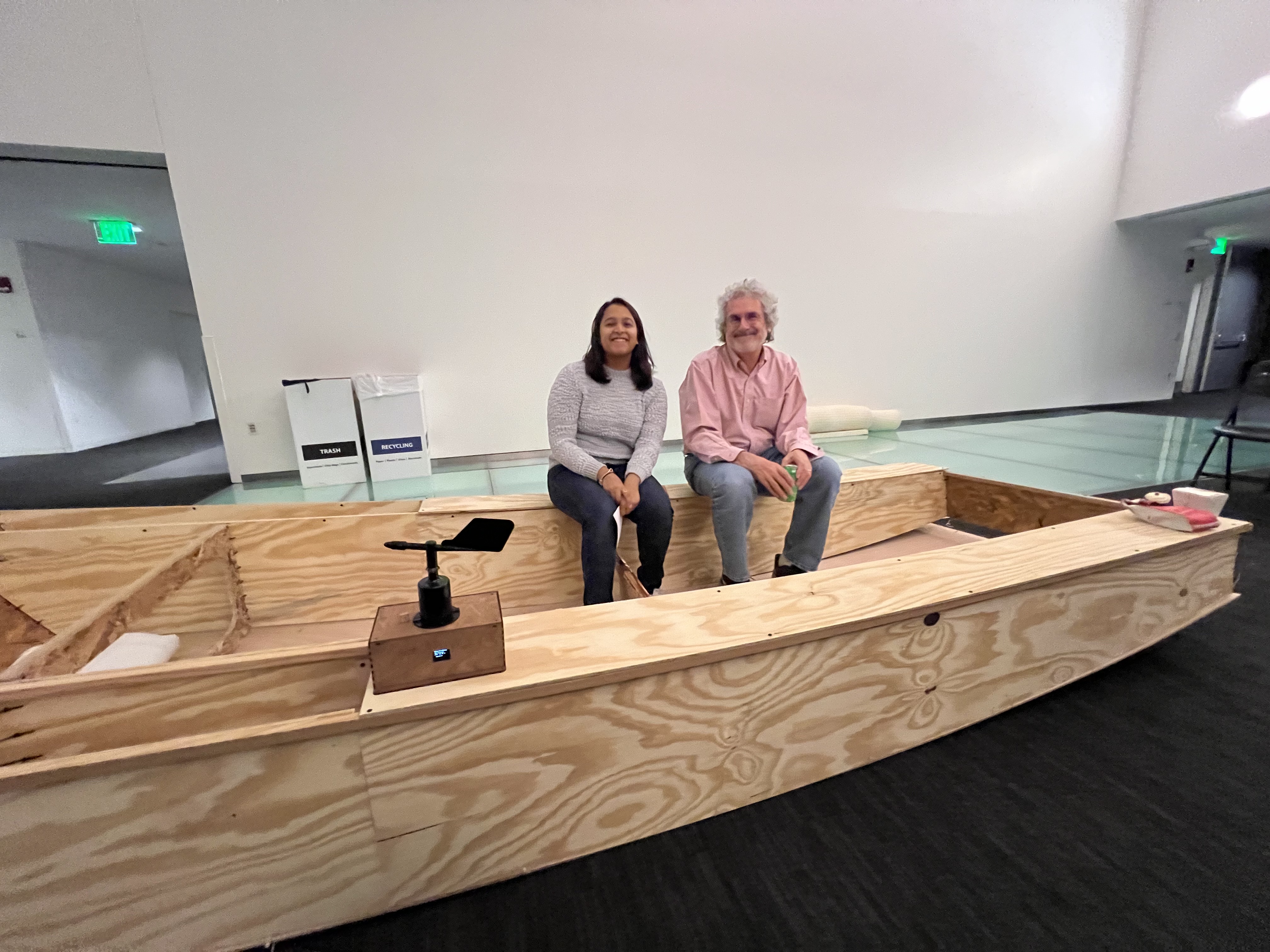
### Making of the boat
We have started to mill the boat!
The process of making this large boat was pretty complicated but the steps are as follows:
1. Designing all the parts in CAD
For now I have the screenshot of the final dxf, my CAD files are in my personal laptop.

Update: redoing some CAD work here. Here is the CAD model for the hull of my boat -

The step files are added to the repo [here]().
2. Cutting all the parts


and many more...
I cut 6 pieces of plywood, actually 7 (because I ruined 1 piece of 4x8 plywood - I cut the wrong dimensions and had to start again). But the boat in total took 6 pieces: 4 pieces of 5.2mm 3-ply and for the base 6mm 5-ply.
The total cost of the whole boat pieces and timber ~$500.
3. Framing the pieces with timber
I framed just the top part of all boat parts (side faces, tanks, bow and stern transom, centercase bulkhead and forward bulkhead) with timber of 3/4" x 3/4" for structural strength. Unlike the actual boat plan for the ozgoose which frames all the sides of the pieces. This is done so parts can be screwed in. But as I will mention in Assembly, I use cable ties to do the assembly of the boat, which doesn't require me to use as much
wood. I stuck to adding as little wood as possible both
to reduce cost but also to use less material. I plan to use epoxy resin on the joints for the bottom and side faces to make up for lost strength.

4. Assembly of the boat
I researched a whole lot to determine the best way to assemble the boat, such that I do not have to disaseemble it again to epoxy the joints and such that I can use as little timber framing as possible. Using zip ties was a great option as I could put this together relatively quickly (the whole assembly took ~1 week).


.
I am very happy with how the boat turned out and learnt a lot through this process of making something big. My lessons briefly were:
- Always double and triple check dimensions before cutting the wood. When exporting svg files from Adobe Illustrator, the program changed the dimensions of the saved file from mm to px. Since I was cutting big pieces and the difference between the two dimensions was pretty small (~50 mm), I could not visually tell that the pieces were going to be smaller. However, once I cut the pieces, I realized they were unusable.
This did not happen once, but 2-3 times and in total I lost little more than one piece of 4x8 plywood and had to use OSB to cover up and finish the project in time.
Here is an example of two pieces that should have been the same width but turned out very different -

- Not accounting for kerf can make assmebly of boats very tricky. Although the kerf size can be small 0.25", it can lead to parts not fitting well together and lead to loss of time, energy, money and wood.
- Transporting and Logistics challenges with making something big. I always wanted a small dinghy, however, what is considered small for sailing is not necessarily something that can be easily transported, stored or carried around.
- I had some great learnings - before taking this class, I was unfamiliar with how to use power tools let alone the many other tools like jigsaw, hand plane, table saw, miter saw, etc, I had to use to make this boat.
.
I am glad that people sat on my boat and this was very fun for everyone.