How to Make (almost) Anything 2023 | Week 9.1: Input Devices
Home
Assignment: Group Project -- Probe an input device's analog levels and digital signals; Individual Project -- Measure something: add a sensor to a microcontroller board that you have designed and read it.
Individual assignment: Measure something
Description: A light sensing input device was designed in KiCad, milled on a CNC machine, and assembled to result in a device that perceives ambient light and provides the corresponding output.
Primary files:
- Phototransistor input device PCB schematic and design (KiCad)
Procedure:
- Design the desired phototransistor circuit in KiCad, using a phototransistor (visible), 10k ohm resistor, and Xiao RP2040 (Note: I also included a 2x3 pin header on the board in preparation for future weeks to continue building upon the board)
- Once the KiCad file has been made, export as a gerber.
- Import the gerber FCu and Edge Cut layers into Quentin's Grb2Img tool, then select "fill edge cut" and "black and white" before exporting render (Note: it is helpful to do edge cut first and press the lock icon next to the dimensions to ensure your FCu and edge cut dimensions align)
- Import the downloaded PNG files into the Mods platform to convert into G-code (1/64 for Fcu and 1/32 for edge cuts)
- Import the F.Cu G-Code file to the desktop attached to the CNC milling machine
- Prepare the CNC by clamping down a sacrificial sheet of copper (bottom) and the milling sheet of copper (top), then secure the 1/64 end mill using the blue guide to determine proper bit depth
- Move bit to x=0, y=0 and then ensure the ground lead is attached to the top of the probe before zeroing the z plane
- After the z dimension has been probed and raised, remove the ground lead from the probe and insert the plasstic cover over the end mill then turn on the vacuum
- Press play on your mill trace
- Upon completion of the mill trace, turn off vacuum, remove plastic cover, and exchange the end mill for the 1/32
- Upload the EdgeCuts G-Code file to the desktop attached to the CNC milling machine
- Repeat the steps above with the 1/32 end mill for the mill outline
- Upon completion of the mill outline, turn off vacuum, remove plastic cover, and snap PCB from the copper sheet
- Inspect the PCB to ensure the trace was clean and as expected; If complications occurred, adjust design as needed and repeat PCB production
- Solder the respective components onto the board and validate the board does not have any shorts
- Within Arduino IDE, program your phototransistor to report the sensor values picked up from light detection
- Connect the RP2040 to laptop and load the desired program
- Validate sensor values are as expected by referencing the serial monitor as light is fluctuated
Key learnings:
- Input sensor values can vary, so remember to normalize when integrating -- Light sensing can vary dramatically based on environment for how drastic of a shift the sensor is detecting; Because of this it is important to keep this value range in mind for future integrations, given the value may need to be normalized for a particular application
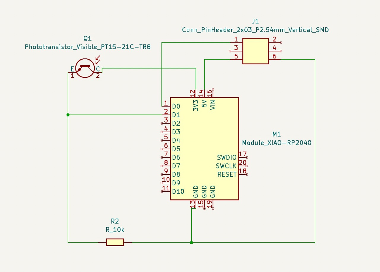
Phototransistor input device schematic design in KiCad
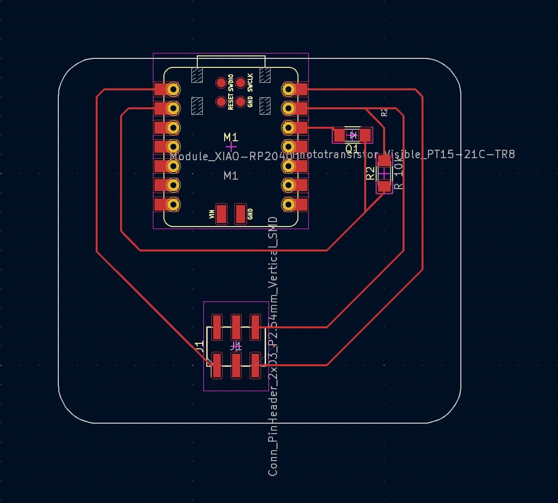
Phototransistor input device PCB design in KiCad
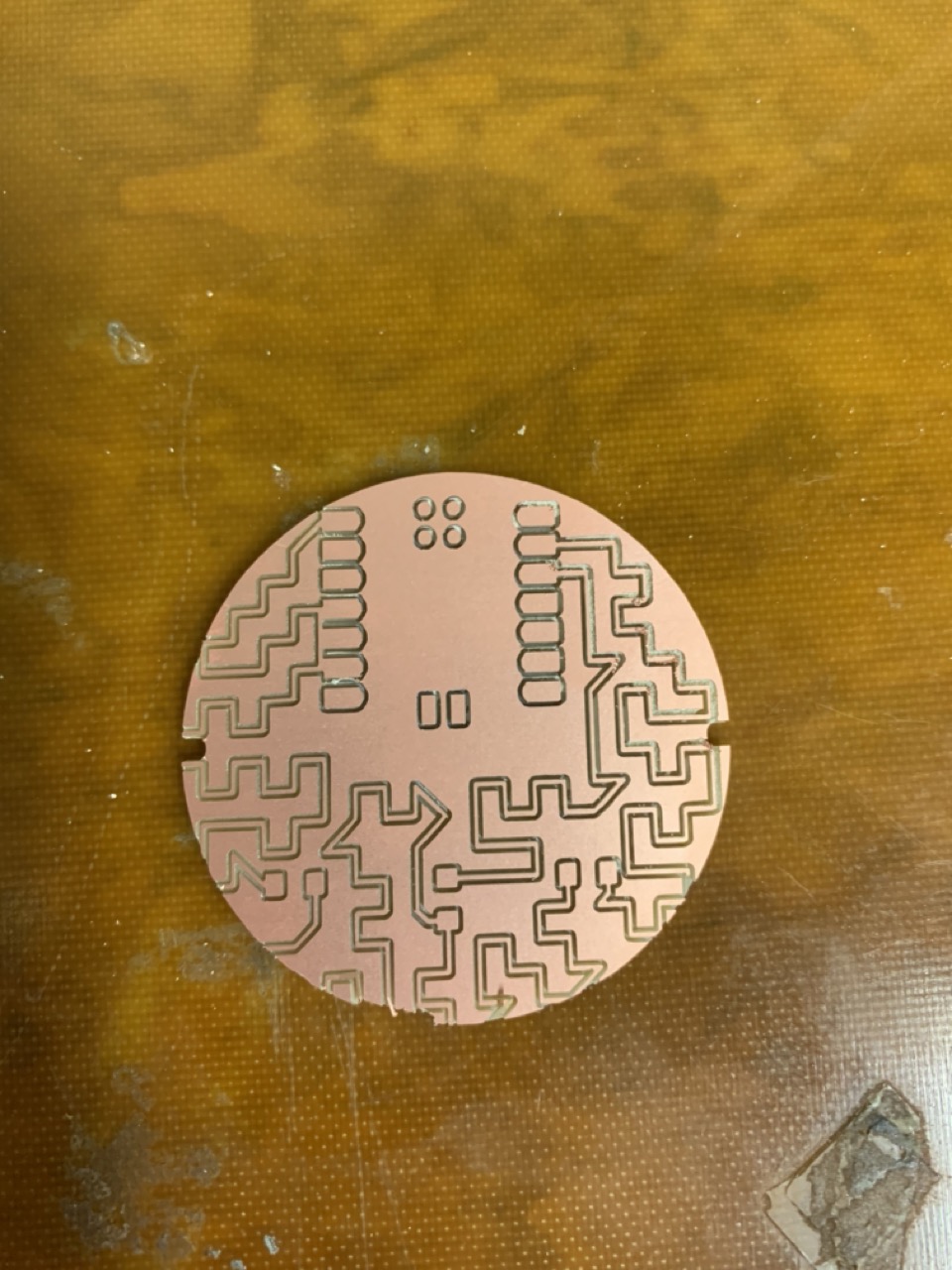
Original phototransistor input device milled with graphical traces for visual appeal, but failed in milling process due to misalignment of the edge cut
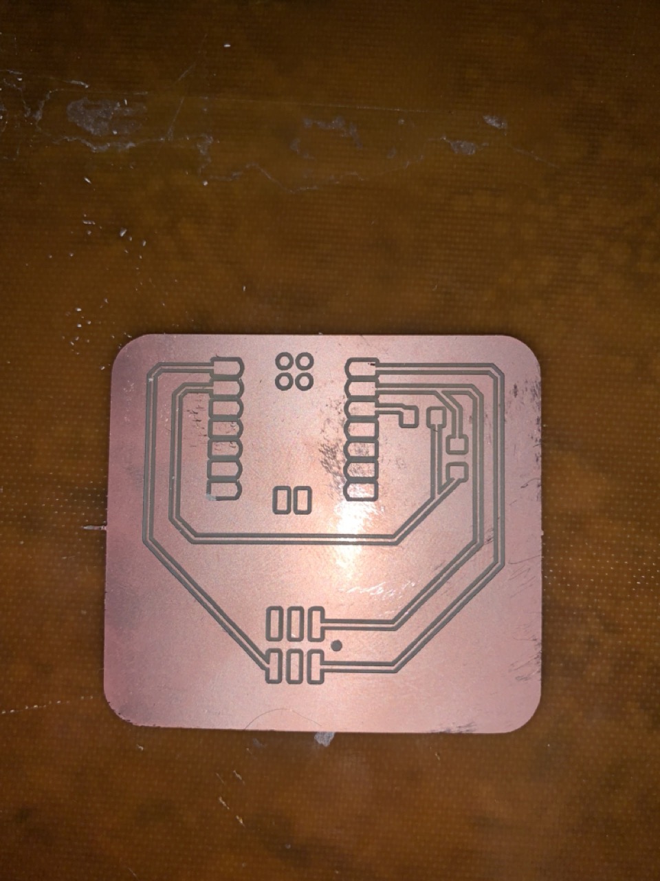
Successfully milled input device
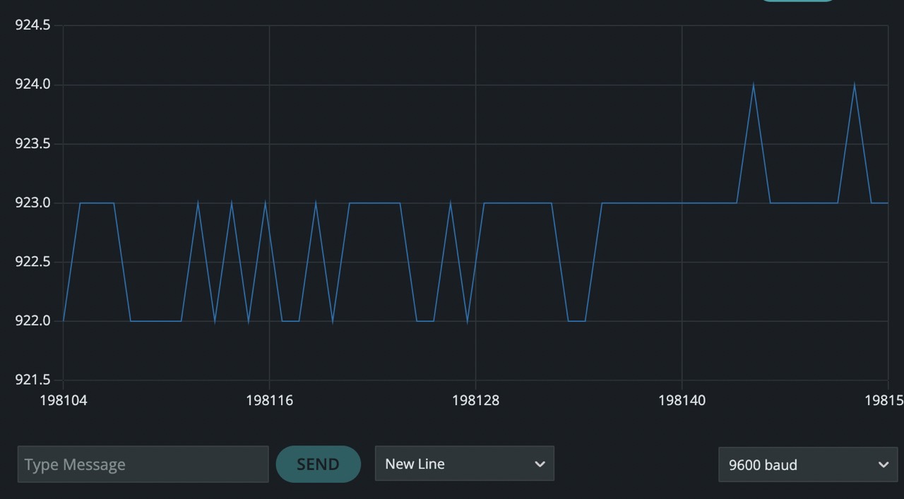
Readout of phototransistor light sensor values in response to changing light