Milling
I milled my board from last week (see below) with the OtherMill in EDS under the instructions of Anthony. A few main notes include take care of the drill bit during switching, attach the safety panel that keep us from the dust, and that the process is pretty well streamline from the hardware and the software that were already available. I used a two-sided board because my board has vias for grounding. The board turned out rather nicely, so I did not have to fix anything.
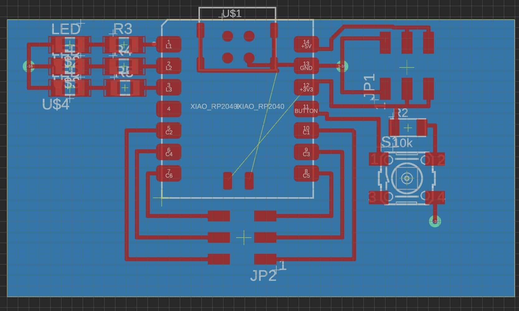
I then find the parts for my board including
- A XIAO RP 2040 board
- 2 x (2x3) connectors that were cut from (2x5) connectors
- 3 LED lights of mysterious colors
- 3 x 1k Ohms resistor to go with the lights
- A button
- A 10k Ohms resistor to go with the button
After gathering my parts, I sat down to solder them onto my board. I learned from Anthony to pre-solder one leg and then place the part down to make it stationary. I managed to burn myself twice while soldering with at least one leaving a visible (and probably permanent) scar.
There is soldering connecting the LED lights in the upper left corner, but I'm hoping that it is fine since they are just going to ground.
Arduino
I attempted to make the light goes on when I press a button. This was not much of a problem since I mostly based it off of the templates available on the Seeed website.
const int buttonPin = D10;     // the number of the pushbutton pin
const int ledPin0 =  D0;      // the number of the LED pin
const int ledPin1 =  D1;
const int ledPin2 =  D2;

int buttonState = 0;         // variable for reading the pushbutton status

void setup() {
  // initialize the LED pin as an output:
  pinMode(ledPin0, OUTPUT);
  pinMode(ledPin1, OUTPUT);
  pinMode(ledPin2, OUTPUT);
  // initialize the pushbutton pin as an input:
  pinMode(buttonPin, INPUT);
  Serial.begin(9600);
}

void loop() {
  // read the state of the pushbutton value:
  buttonState = digitalRead(buttonPin);
  // Serial.println(buttonState);
  // check if the pushbutton is pressed. If it is, the buttonState is LOW:
  if (buttonState == HIGH) {
    // turn LED off:
    Serial.println("button high");
    digitalWrite(ledPin0, LOW);
    digitalWrite(ledPin1, LOW);
    digitalWrite(ledPin2, LOW);
  } else {
    // turn LED on:
    Serial.println("button low");
    digitalWrite(ledPin0, HIGH);
    digitalWrite(ledPin1, HIGH);
    digitalWrite(ledPin2, HIGH);
  }
}
Integration
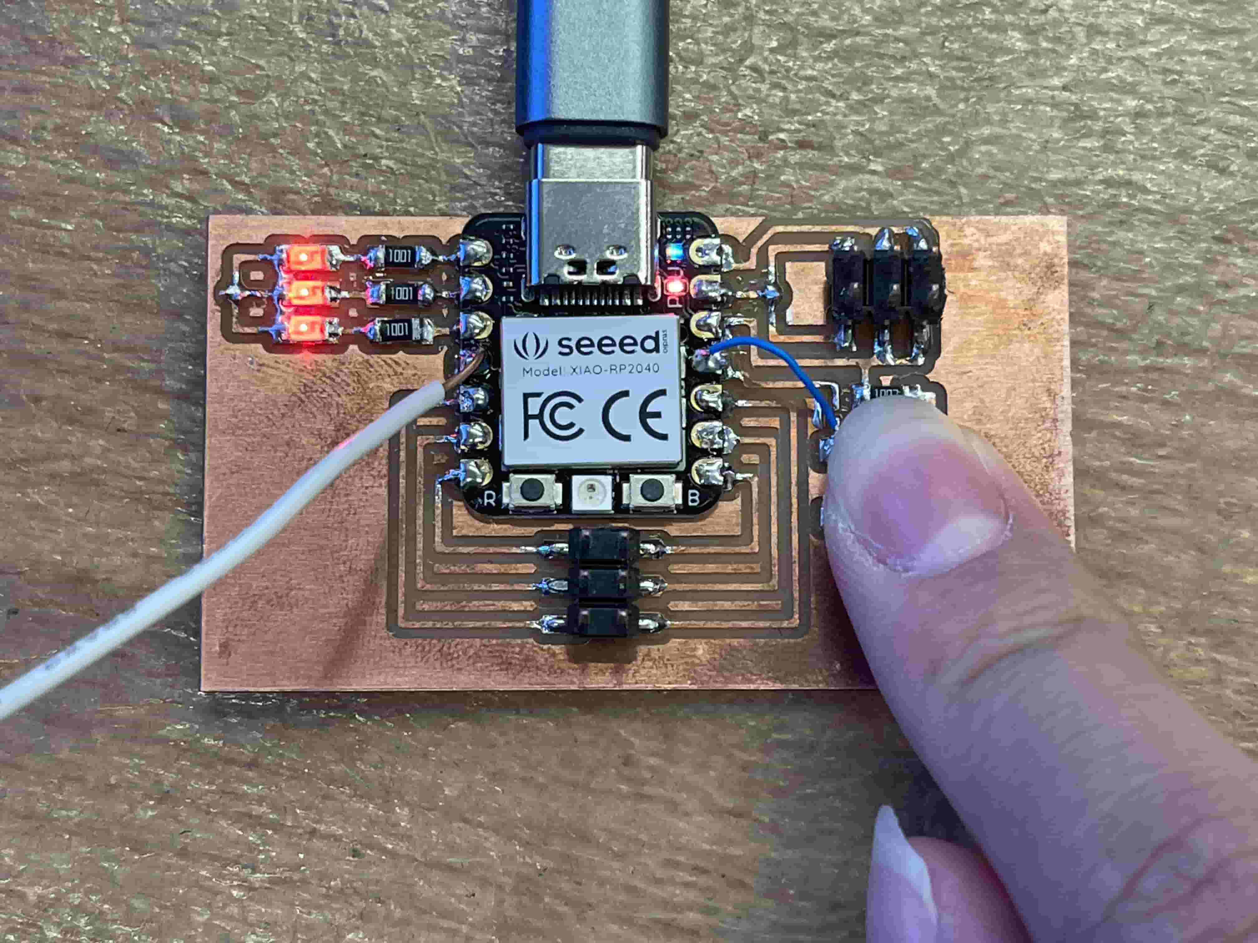
However, the problem arise when I try to upload the code to the board. The button was reading high regardless of when I press it or not. It took me three weeks to fix this problem--when I need the board for input device week. Maya (EECS TA) and I thought it was because I connected the wrong wire to the button, but it was actually because I never connect the top and bottom board surfaces! My ground via wasn't really grounding!
Before I realized what was really wrong, I modify the button by cutting out a connection and jump a wire to another. This make the button report the right thing on the serial monitor. However, this broke when I connect my top and bottom board surfaces through my via which was not done by divet(?) because my via was too small; I connected them by running a wire through the hole and solder the top and bottom part.
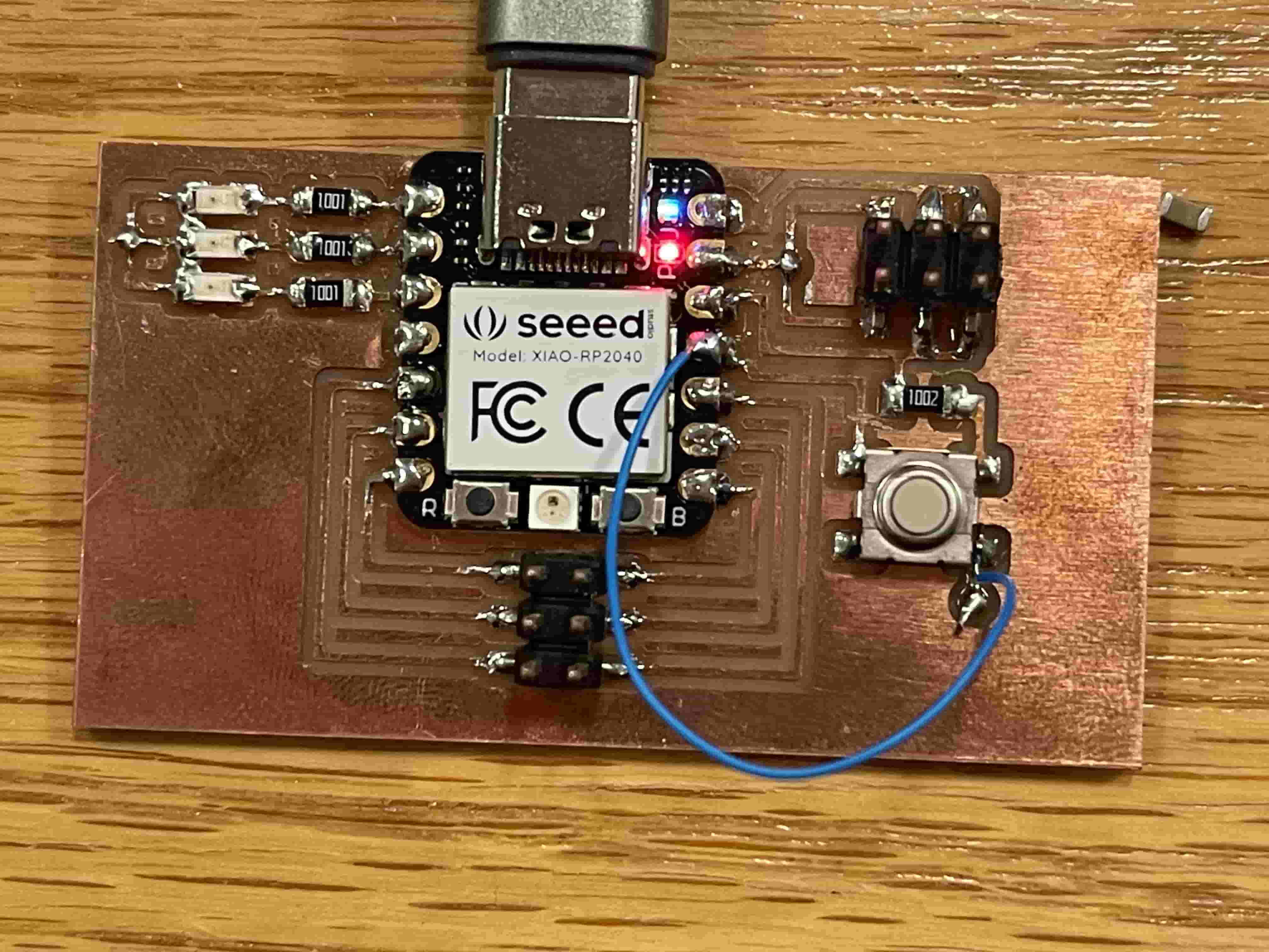
To fix the mistake the I have made for myself, I de-solder the jumper cable and solder a cable to reconnect the cable I have cut instead. The product is below. Please disregard the white wire which come to use in week 8.