The assignment this week: make a parametric construction kit, using a laser cutter
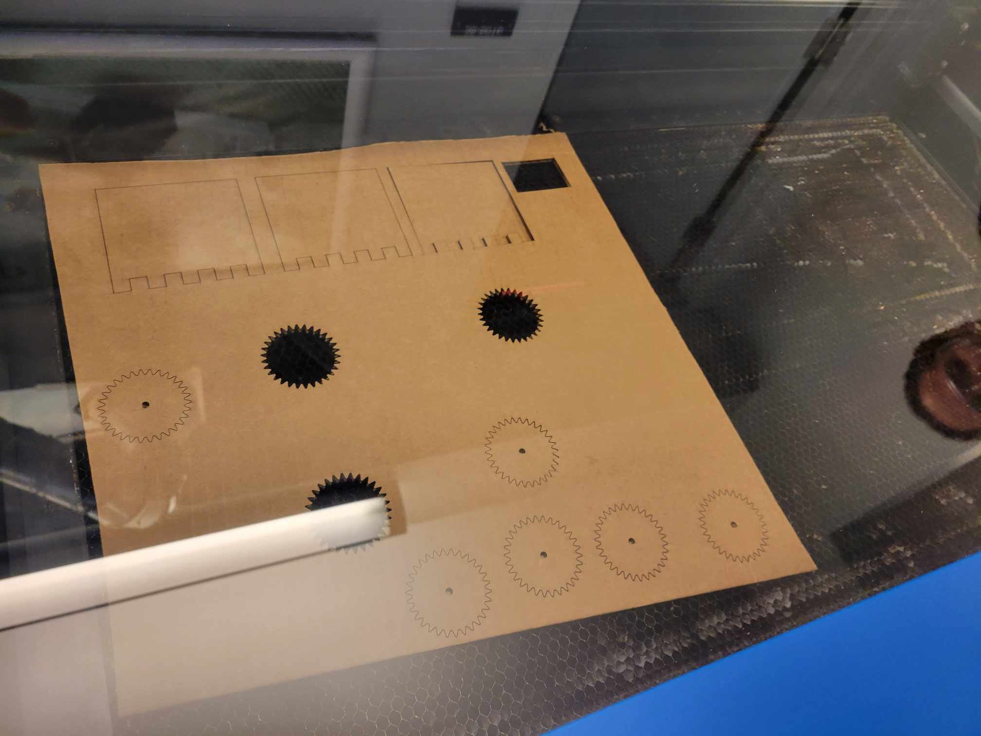
A group of us printed some comb designs to discover the right power, speed, PPI to use. Sungi suggested we keep it at 100% power and 500 PPI, and adjust the speed from there. We tried to use it at 40% speed, 20% speed, and 15% speed. As you can see, 15% was perfect.
We also laser cut a simple rectangle and measured it with calipers to estimate the kerf at .5 mm
I had a little trouble getting the experiment for the press fit right. I had initially subtracted the kerf from the teeth, and added it to the holes, and as pictured, that made for a very loose fit. Things worked a little better when I added the kerf to the teeth, and subtracted from the holes.
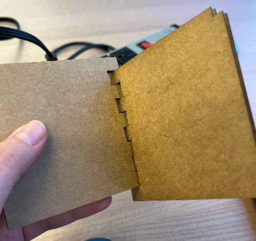
I also moved away from desigining "teeth" joints, because I wanted to use press-fit joints, anyway. These were a little easier to iteratively design. My first attempt ended up too loose, but when I measured my cardboard, I discovered that this was simply because I was using the wrong cardboard thickness in my CAD design. For a chamfered joint, I found the connection was best when I accounted for the kerf and no extra space for the joint to press. I guess cardboard is malleable enough, and the chamfered joint is forgiving enough to make it fit well.
I want to make something with wheels, so I'm designing a wheel and a cross bar to connect the wheel back to the rest of the construction kit, which I intend to be pretty simple. Here are my initial designs:
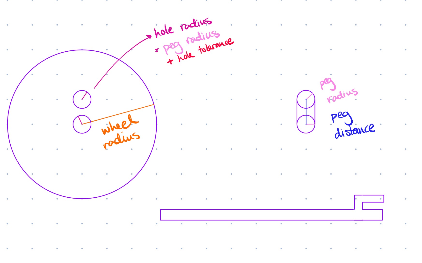
I realize, though, that there's a major problem with this design. How am I supposed to laser cut the cross bar? It's made out of a rectangular, mostly flat piece of cardboard. I can't cut that into a cylindrical rod. So I designed a rectangular rod, instead;
But then I ran into another issue, once I started designing the basic construction pieces. I want the cross bar to rotate with the wheel (that's why the stabilizing peg is there). But I want the basic construction pieces to stay stationary while the cross bar rotates. This is not going to be possible with a square peg.
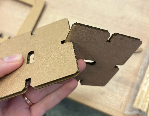
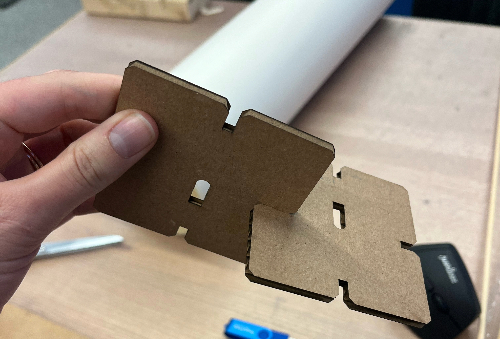
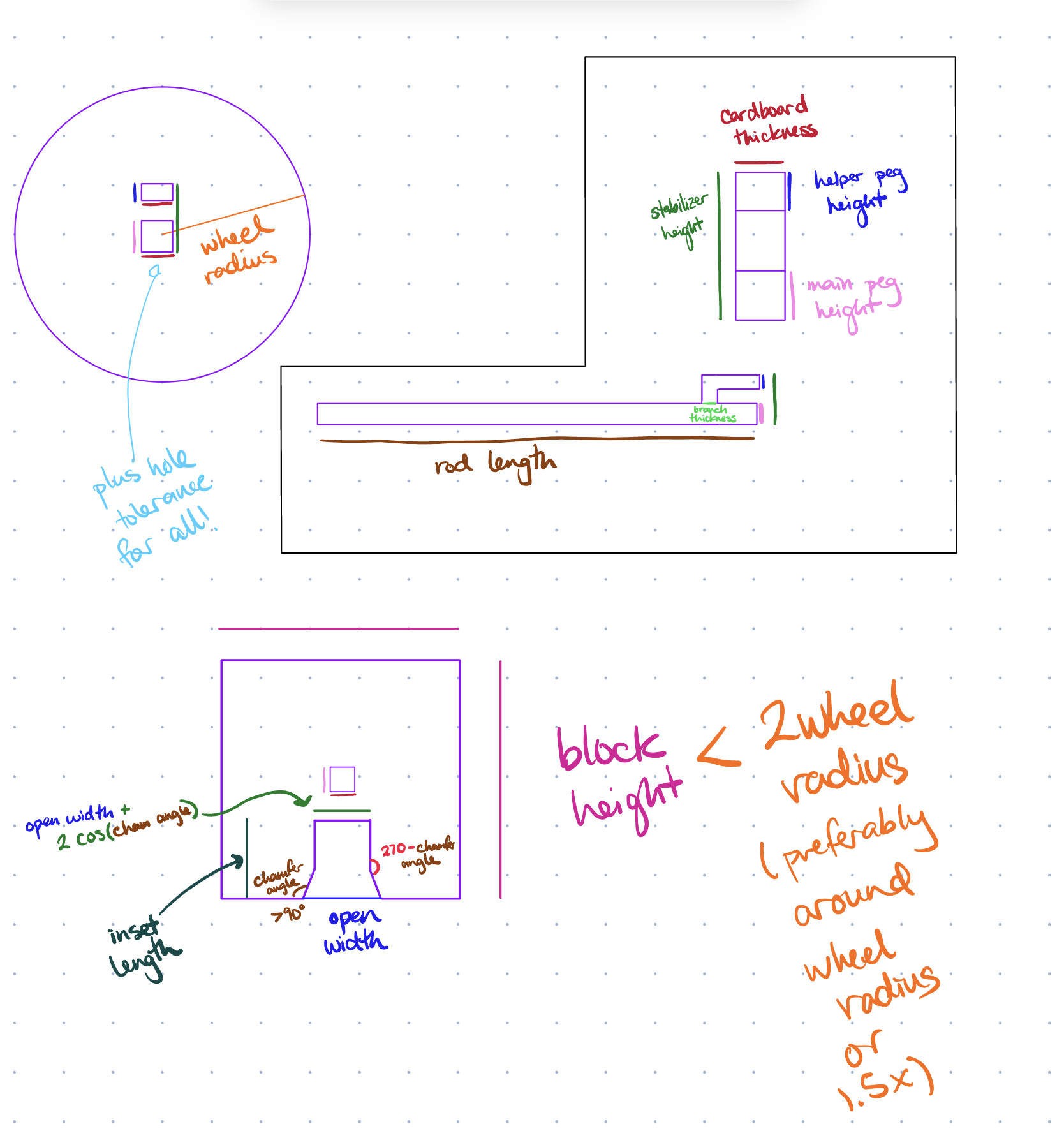
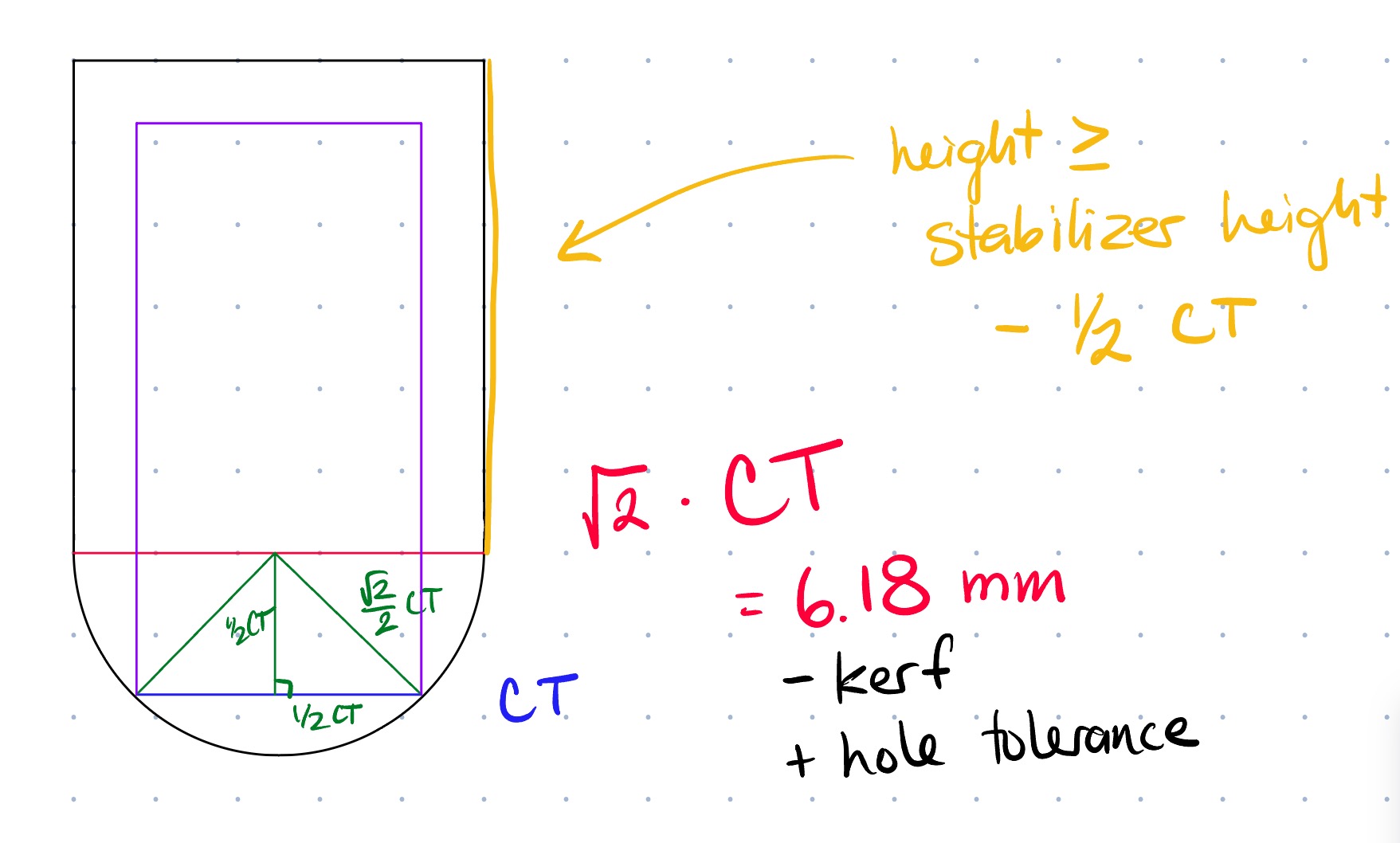
...Or is it? Perhaps I could make the pegs exactly square, then have the hole in the basic pieces be oval (so the stabilizing peg can pass through), with the short diameter the length of the square diagonal. I never saw this idea through to completion, but I made some designs for it, and printed them while iterating on the joint sizes.
I discarded this design, because as Anthony was talking to people in the lab, he asked about my design, and reminded me that I don't have to make EVERYTHING with the laser cutter. He directed me to some very nice wooden rods, which I adjusted my designs to utilize.
After characterizing the laser cutter's parameters and kerf, I designed some nice little blocks and a very simple wheel to match. The blocks are maybe a little bigger than they need to be. But the dynamics of the system work beautifully (the rod clamps to the wheel, but slides through the press-fit blocks).
After decreasing the size of the pieces a little and cutting the rods to the right length, I assembled a working vehicle!
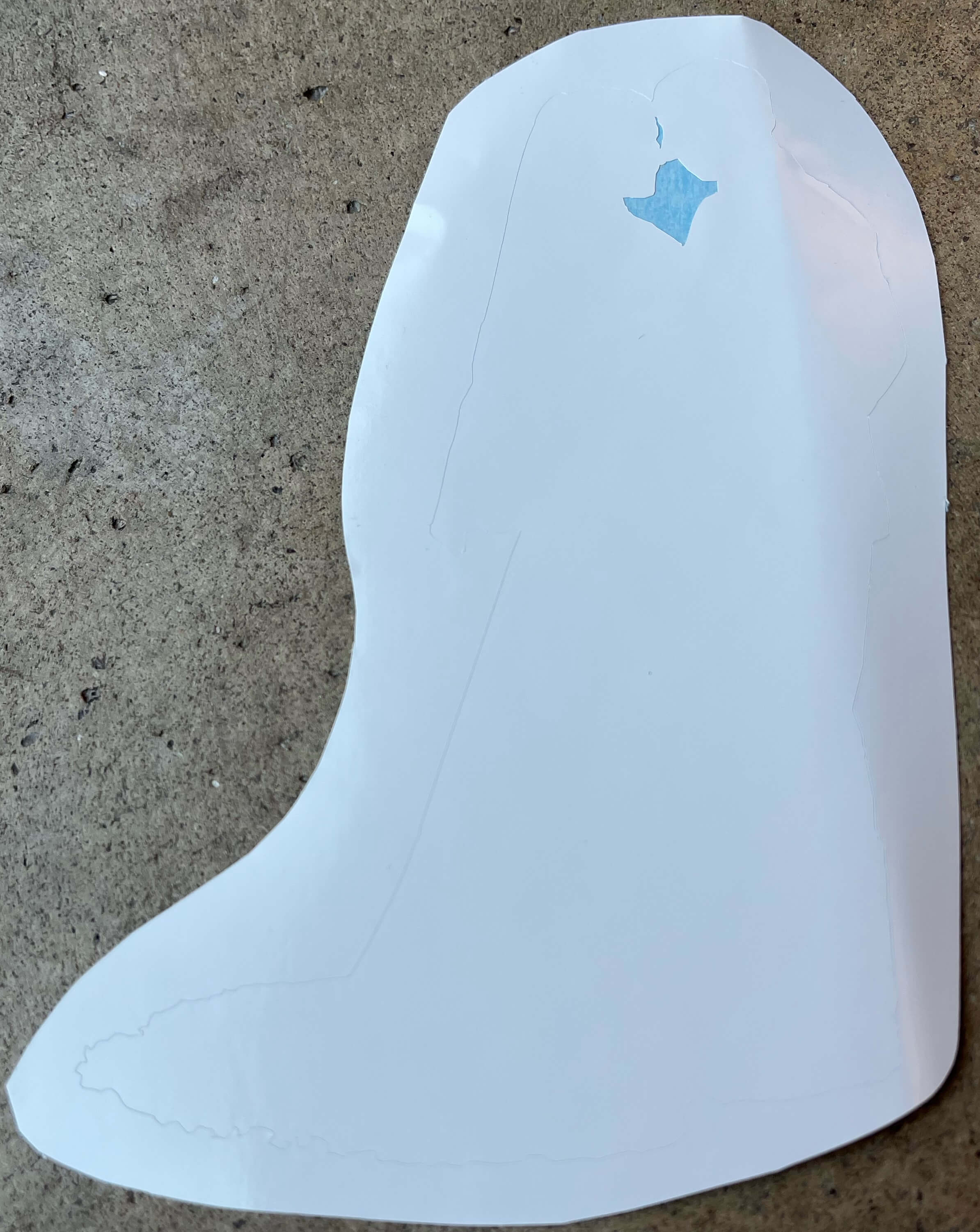
For my vinyl-cutting project, I made a sticker out of the silhouette of one of my bridal photos. It was an adventure in using adobe illustrator, and combining a LOT of vectors so it would only cut the silhouette. I think it turned out great! I haven't figured out what to stick it on yet, but here it is (as well as the svg, so you can see the lines a little better).
