The assignment this week: Make and test the development board that I designed last week
I tweaked the design a little from last week, actually. I realized that I had connected the button to ground, but I had not pulled out ground to a header pin. Since one of the header pins was unused in my design, I created another connection from ground to that pin.
Additionally, when I first went to print the circuit board, Anthony pointed out to me that my traces were quite small, and that I should probably thicken them up a bit on my design. I had not changed the trace thickness from the default (6 mil), so I was grateful for the extra durability of my board when I changed it to 16 mil.
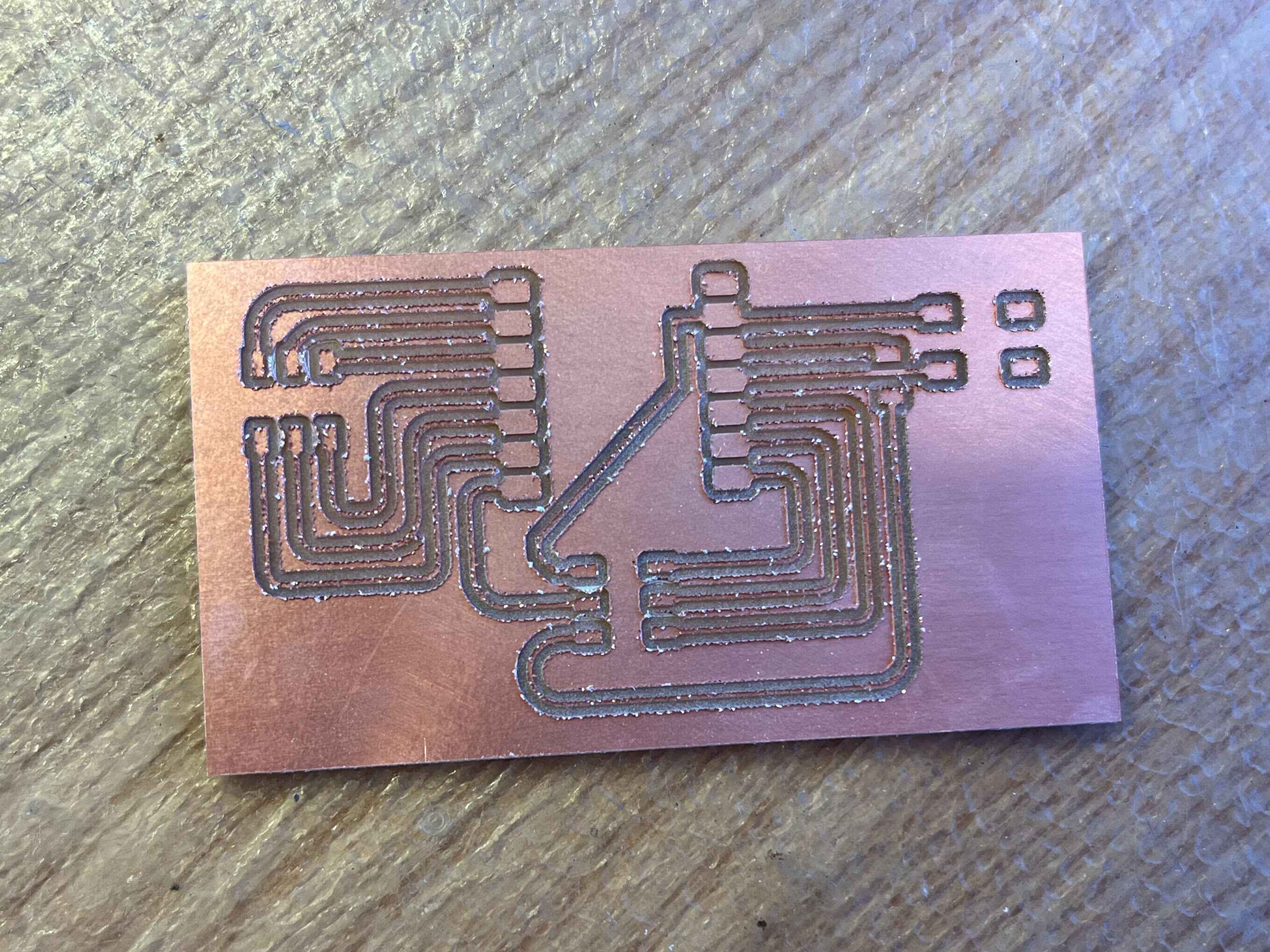
Here's the adjusted design.
I printed my project on a PCB mill. A few of the pads for the microcontroller pins were close enough together that I had to use the 1/64" bit between them, but most of the design was easily doable with the 1/32" bit. The job took about 20 minutes to complete. I was surprised at how much dust was created! I suppose it makes sense, though, since the dust is a lot less dense than the solid material I was milling out.
I used the same scraper to get my board unstuck from the mill, and to sand off the fuzzy edges from my board. I was afraid to lift up the traces, and as a result I think I left the edges more fuzzy than would have been ideal. I also noticed that some of the rough edges from the traces were getting in between the traces. I was worried that would result in unexpected connections between the traces, so I tried to weed out between those traces with some tweezers. Looking back, I wish I had used sandpaper to more fully smooth out the PCB.
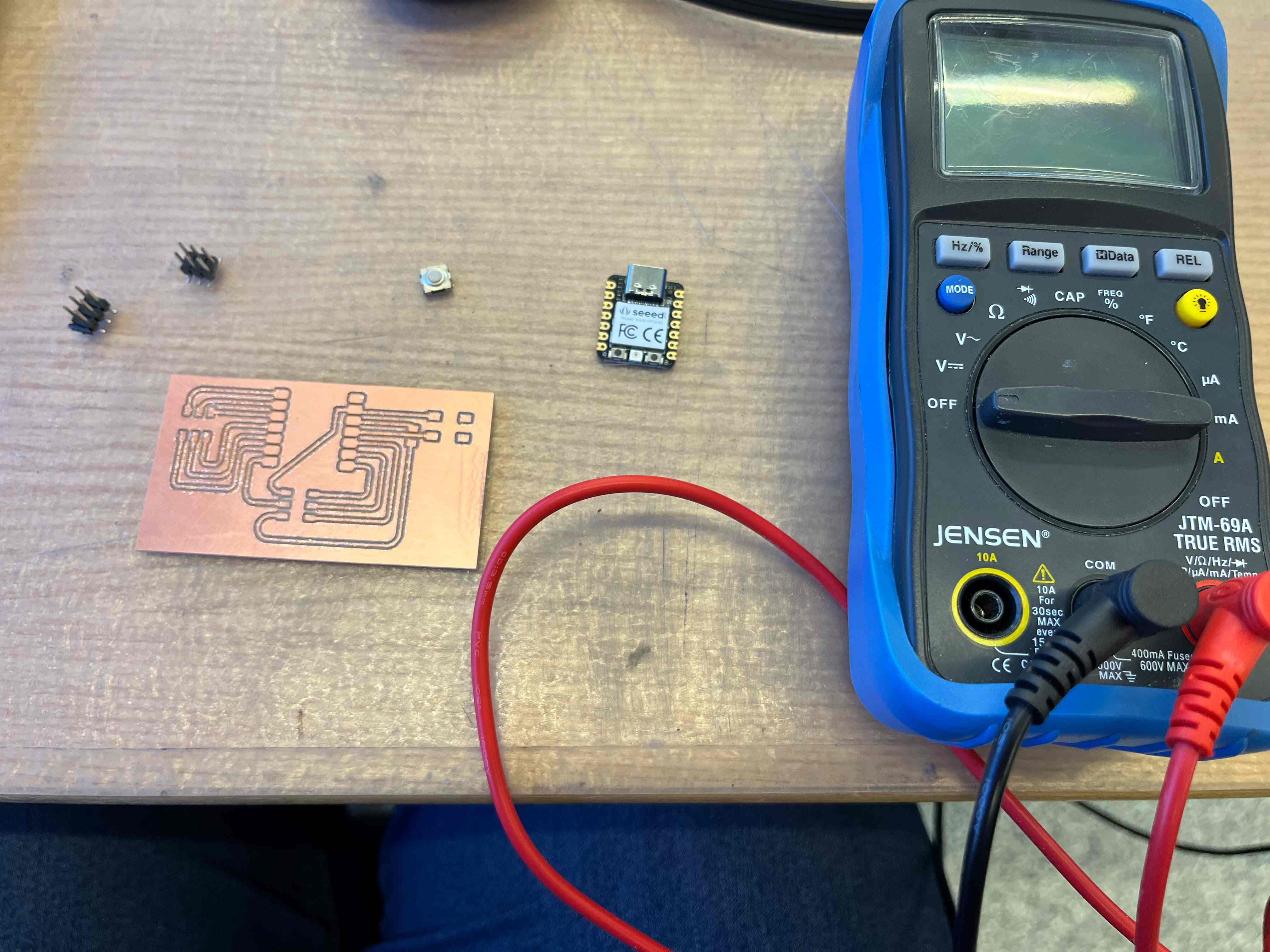
After smoothing out the board, I wanted to test connections between the traces, to make sure that I hadn't missed any lingering unwanted connections, and that I hadn't disconnected anything I intended to be connected. I used a multimeter to check that each pad was not connected to the background copper, that each pad was connected to the pad(s) at the other end of the trace, and that neighboring pads weren't unintentionally connected. There was a bit more weeding I had to do with the tweezers after this testing, so I was glad I tested it before soldering anything.
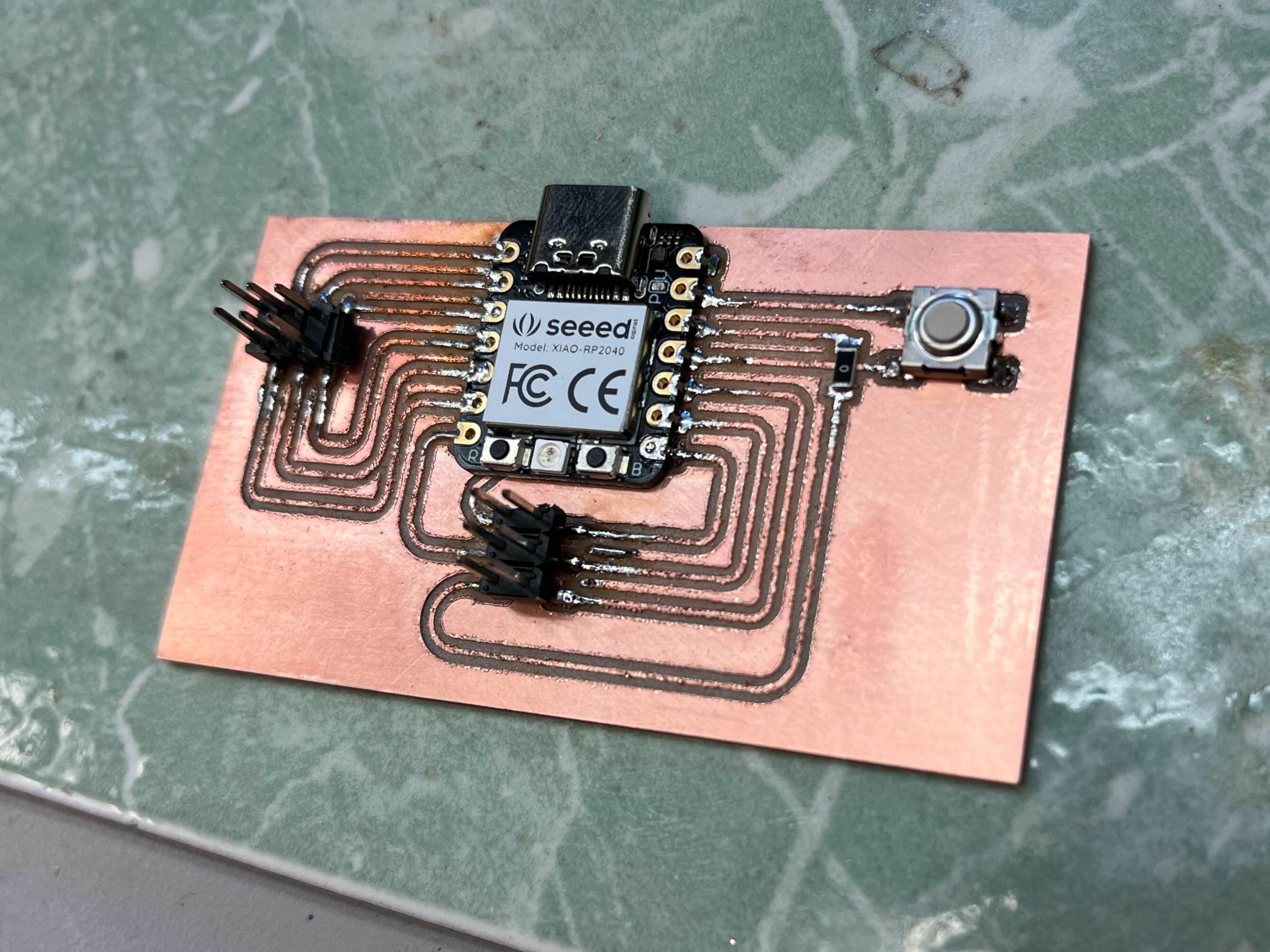
After soldering a few connections, I realized that I had forgotten to tape the underside of the microcontroller! In the design, I had used the footprint that taped over the connections underneath the RP2040, but I'd forgotten to actually put on that tape before soldering. So I got a great impromptu lesson on desoldering. I learned how to use the solder braid, the desoldering gun, and hot air to get the solder off. It was the hot air that finally did the job; probably because four pins was a lot to get sufficient solder off. I'm glad it wasn't any more than that, otherwise I might have needed to start over.
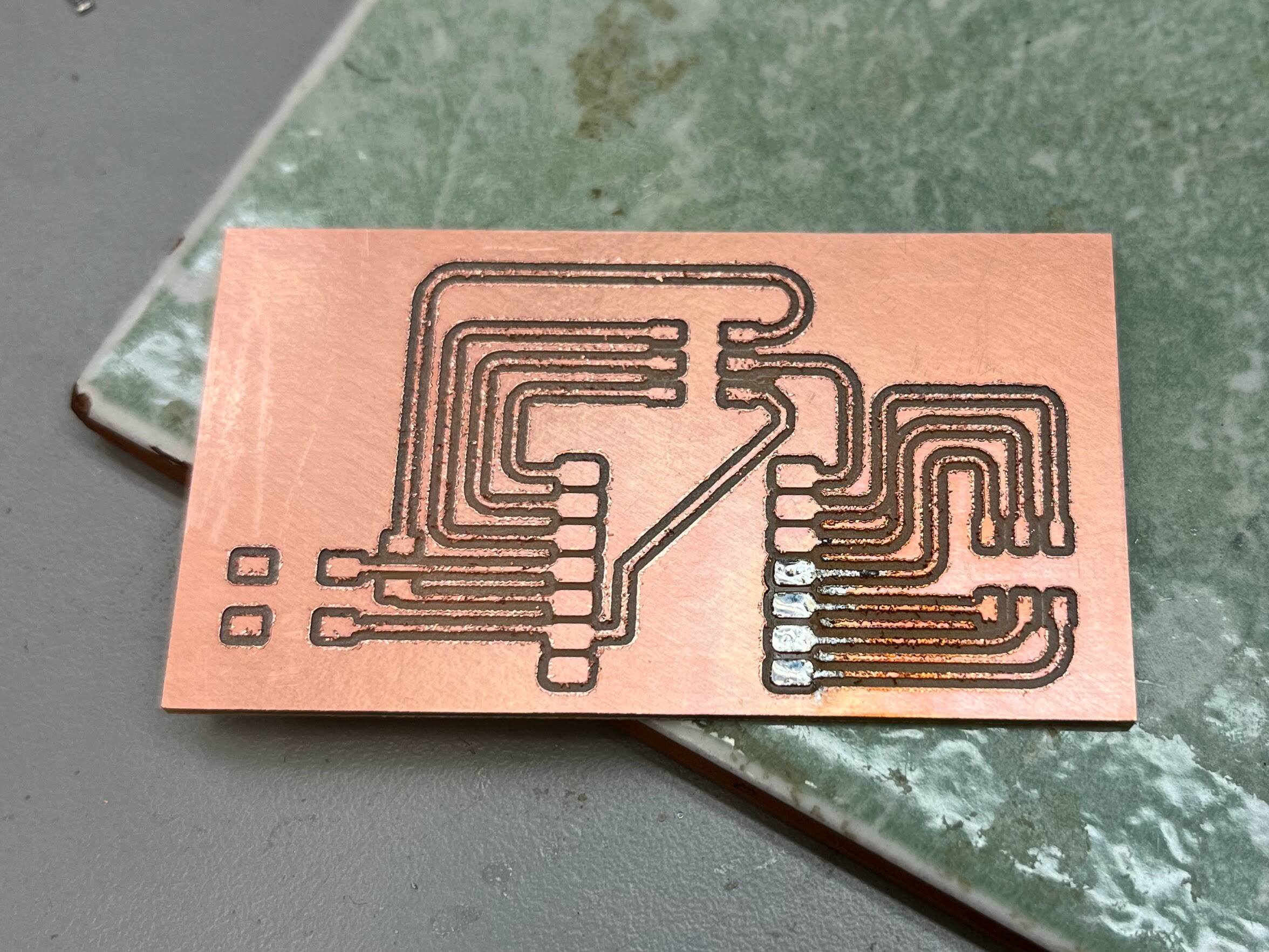
Once I took off the microcontroller and taped up the back, I was ready to go soldering again. Up to this point, I had only soldered pins in through holes, so it was a new experience to solder loose parts onto a flat surface. I found it difficult to get my parts to stay in place, especially the 0 ohm resistor. The PCB resistors are tiny! I also found it difficult to get the solder to take to the board and the component, instead of directly to the soldering iron. Somehow I managed, and now I have a cute little circuit board for my microcontroller! I continued to use a multimeter to test my soldering joints as I went. Some of the neighboring joints said there was a connection, just with several megaohms of resistance. I figured that was sufficient resistance that it wouldn't make a very big difference in practice, but I haven't exactly tested that yet.