Idea
Making a dice out of metal. Initially, I wanted to do 3D engraving of metal, but the software had limited capabilities. On the side, I was practicing welding to build my bike during IAP.
MIG Welding Practice
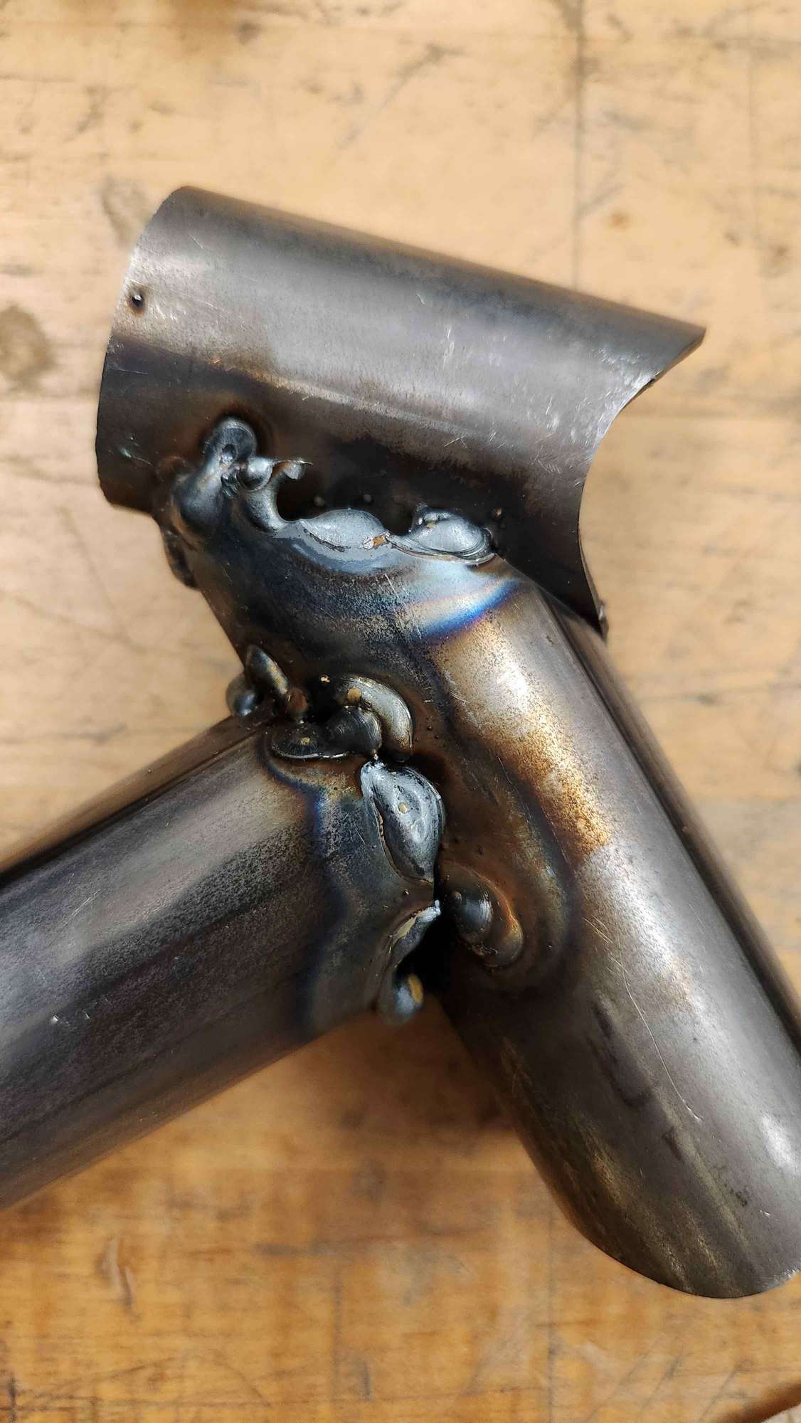
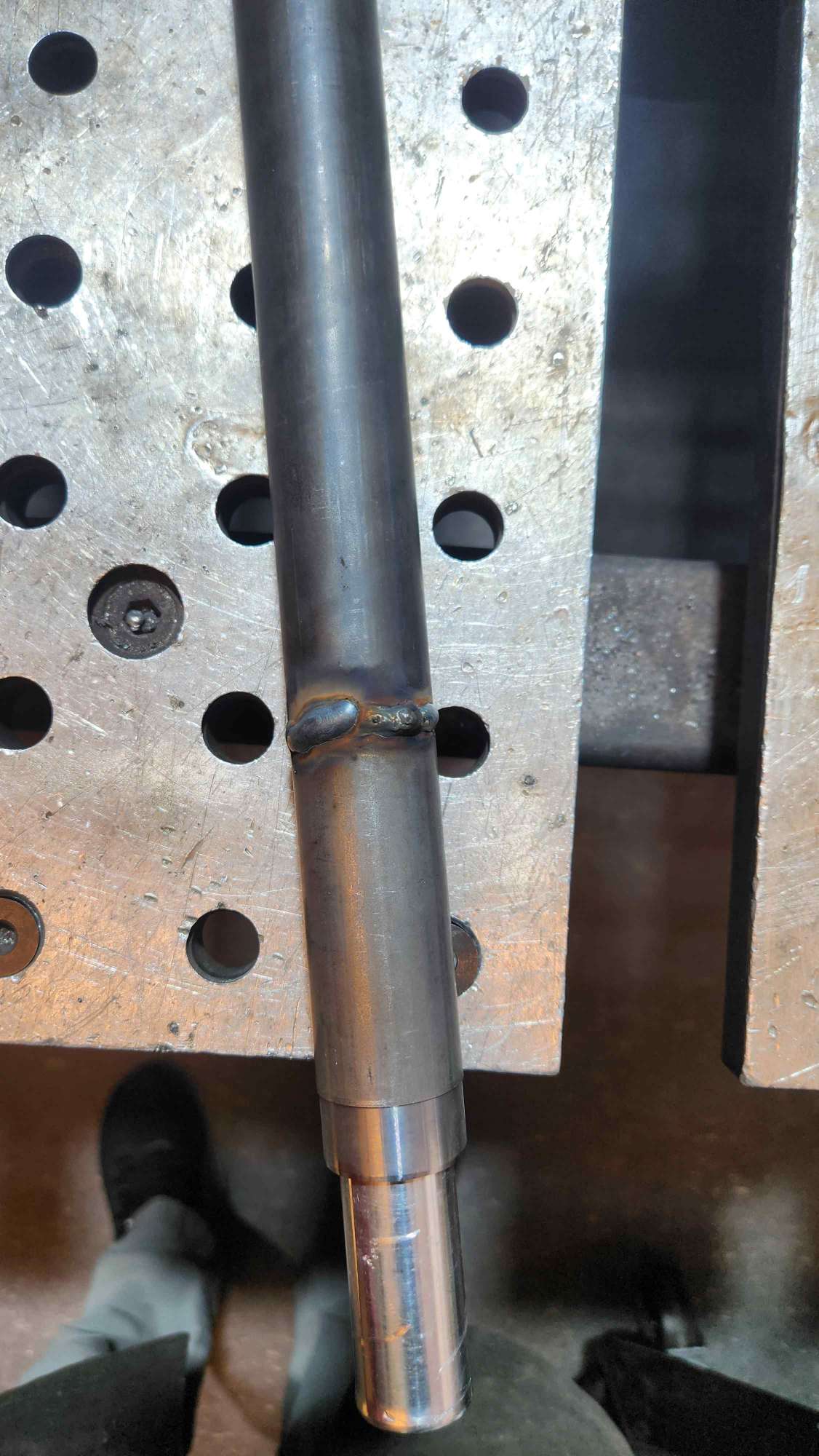
Since I wanted to join Build Your Own Bike class during IAP, I learned how to welding then weld tubes.


Dice 1
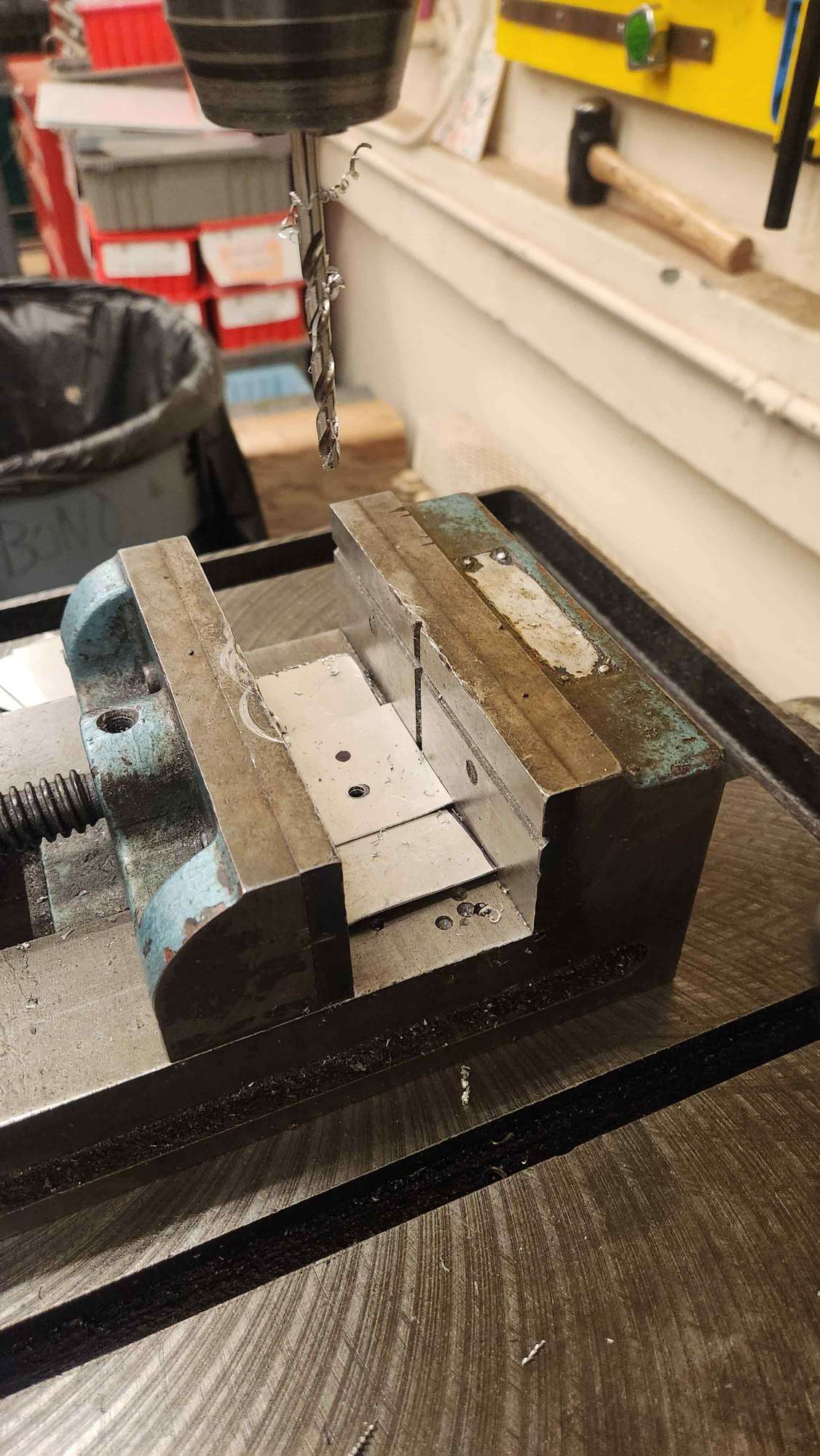
I started simple here. I wanted to make a dice of 6 faces out of metal sheet (aluminum), used cutting pliers to cut 6 scared, then the drill press to cut holes. Here, I didn't know that there are laser cutters for metal and really apprecitated usual laser cutters. After, I set up the welding station, but then looking at the cataloge I realized that there is not clear setting for aluminum. I tried to see what happens but it created a burnt spot and did not give a nice welding sound. Later, I learned after talking to Jack (D-lab) that there is different setup for alumnim welding.


Dice 2 ~Kiragami
Here, I came to CBA. I wanted to use all the features of thee Fablight. Thus, I wanted to raster a pattern, then engrave the bending guides, then cut the dice pattern and numbers. I used Illustrator to make the outline of the design. Then I exported it as DXF. I spent a lot of time and coming back and fourth. OMAX and Fabcreator do not like newer verions of DXF files. Also, exporting in Illustrator will get all the layers even when you hide a layer. I tried to simplify the pattern and tried various ways to make the design visible in OMAX. Unfortunately, Fabcreator did not like the pattern and I eventually moved ahead with only using the cutting layer.
As a process, to send a file to FabLight device, you need to take your DXF, edit it in OMAX then export it. This is sometime important because FabCreator is an OLD buggy software, and does not understand all files.
Experiment 1
Software


Fablight
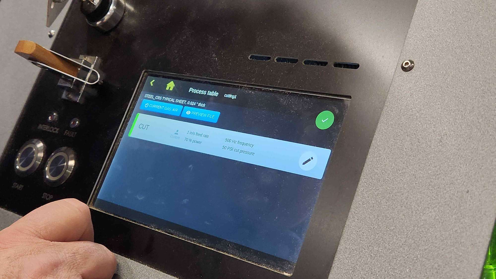
Cutting using the Fiberlight in my case was simple, because John gave me the correct setting of speed and power for the material I was using. I was surprised of how quick cutting steel is compared to Aluminum.
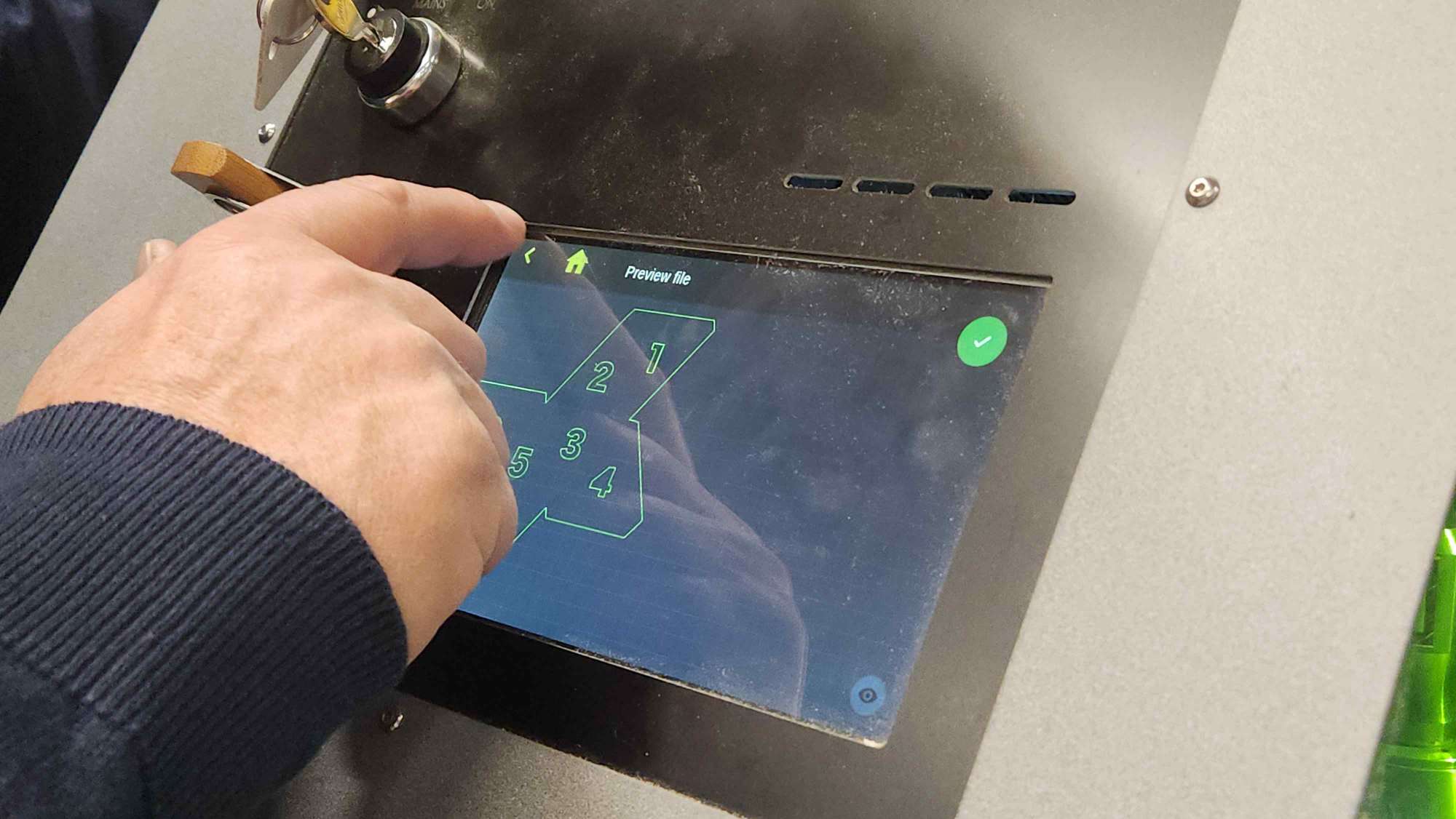
You take the FabCreator file, put it in a USB, and then adjust the setting and preview for cutting.

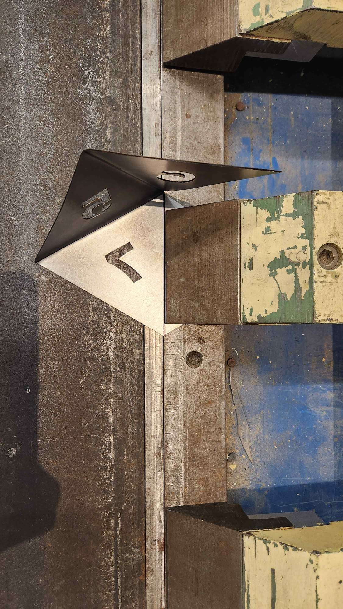
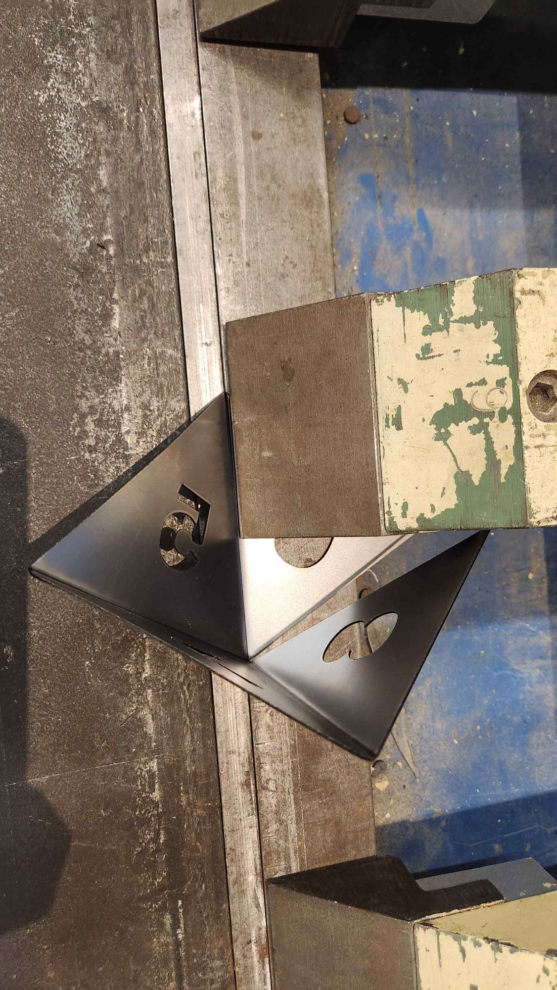
Here, we used finger brake machine and a Vise to bend the edges. It looks messy. We tried cutting at then fixing it, but it was beyong rescue..
Bending

Experiment 2
John and I though it will be a better idea if we have two halfs, since it was tricky to access the inner bends. So, I fixed the design in OMAX
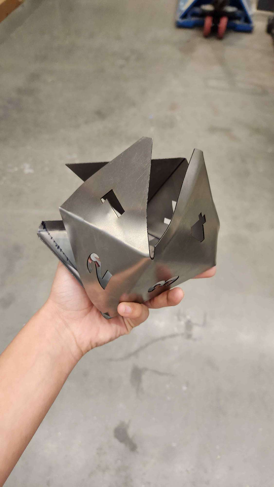
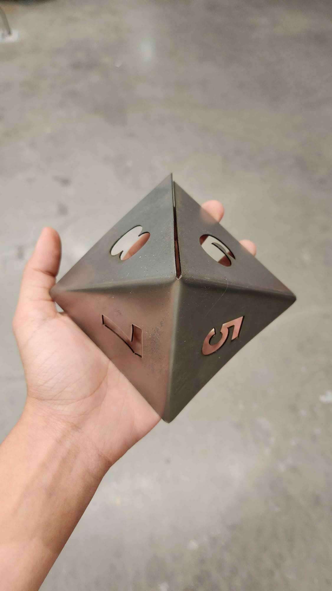
Fablight Result and Bending Process

Bending Result
Bending was much more srightf-forward. I used the angle-meter? to make sure each bend is roughly 90 degrees. However, I made the first bend less to make space for the last bend to put in the finger brake as you can see in the picture above. The result were much cleaner than the previous experiments.
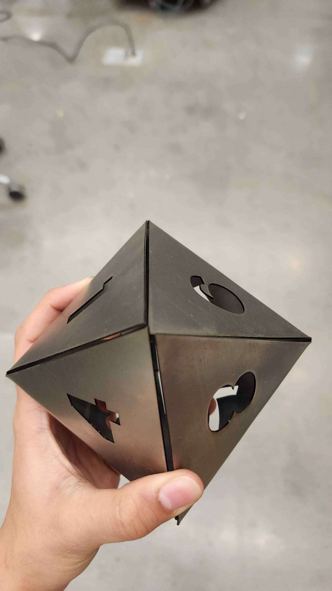
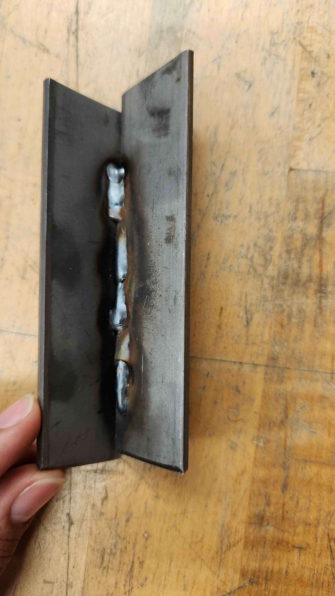
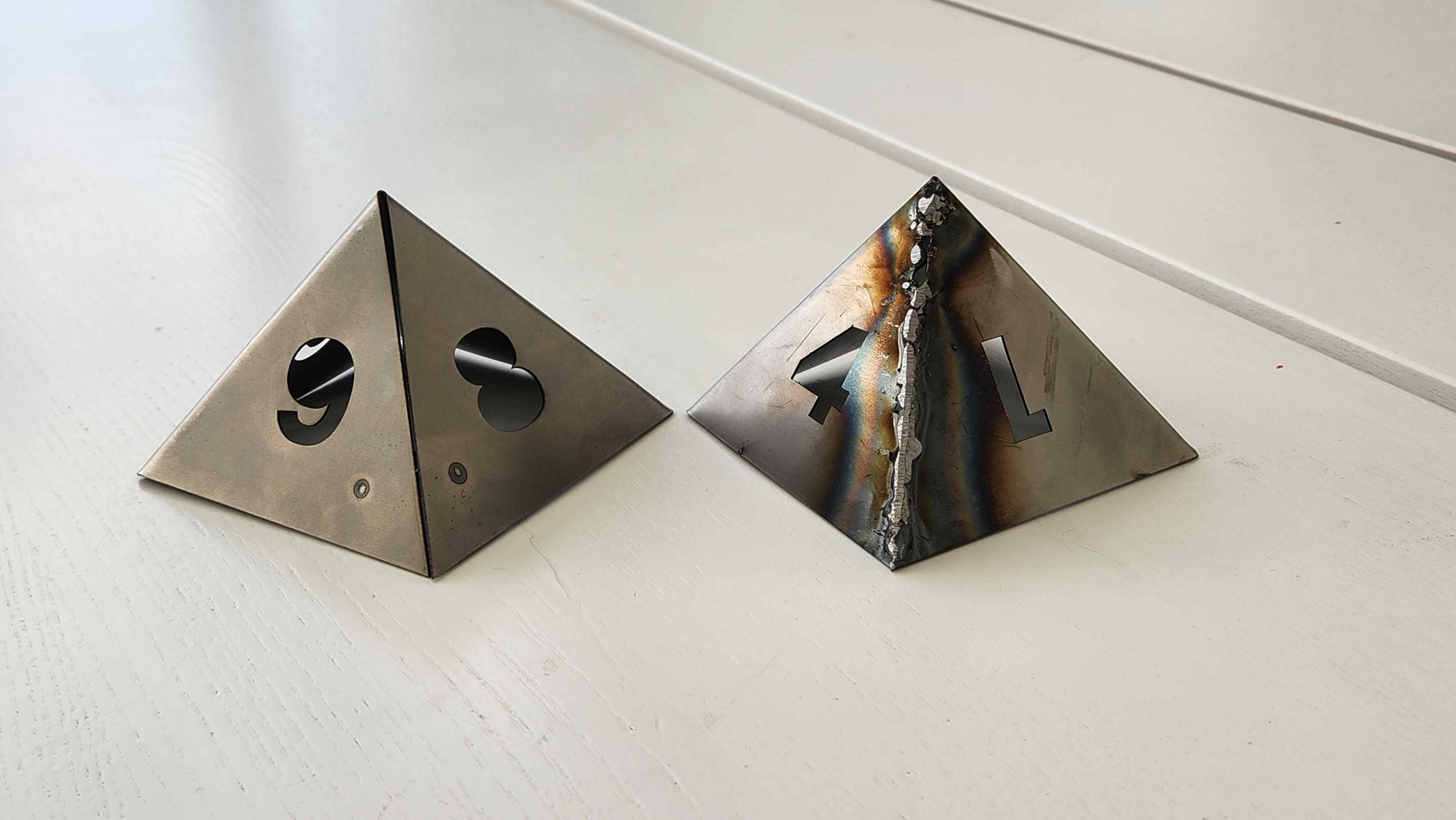
Welding
Now, we tried two methods. I started with MIG welding. I was not as experienced dealing with thinner sheets, thus I immediately made holes through it. As you can notice in the picture, lower part was done by John, but the uper bubbly part was done by me. After, we used a bench grinder to smooth out the weld. The second method was sport welding. I cut two strips of 5mm*25mm, bend it and attached it to the inner part. the finishing of it was much cleaner than spotwelding.
Final Result

Future Work
Making a bike handle to house my electronics
Assignment Description
Design and produce something with a digital fabrication process (incorporating computer-aided design and manufacturing) not covered in another assignment, documenting the requirements that your assignment meets, and including everything necessary to reproduce it.