Idea
Make a breakout board to access all pins via the headers. The board will be able to use external power sources and it's easy to use and integrate and use for projects. I wanted to make it easy to reuse this microcontroller when changing the project
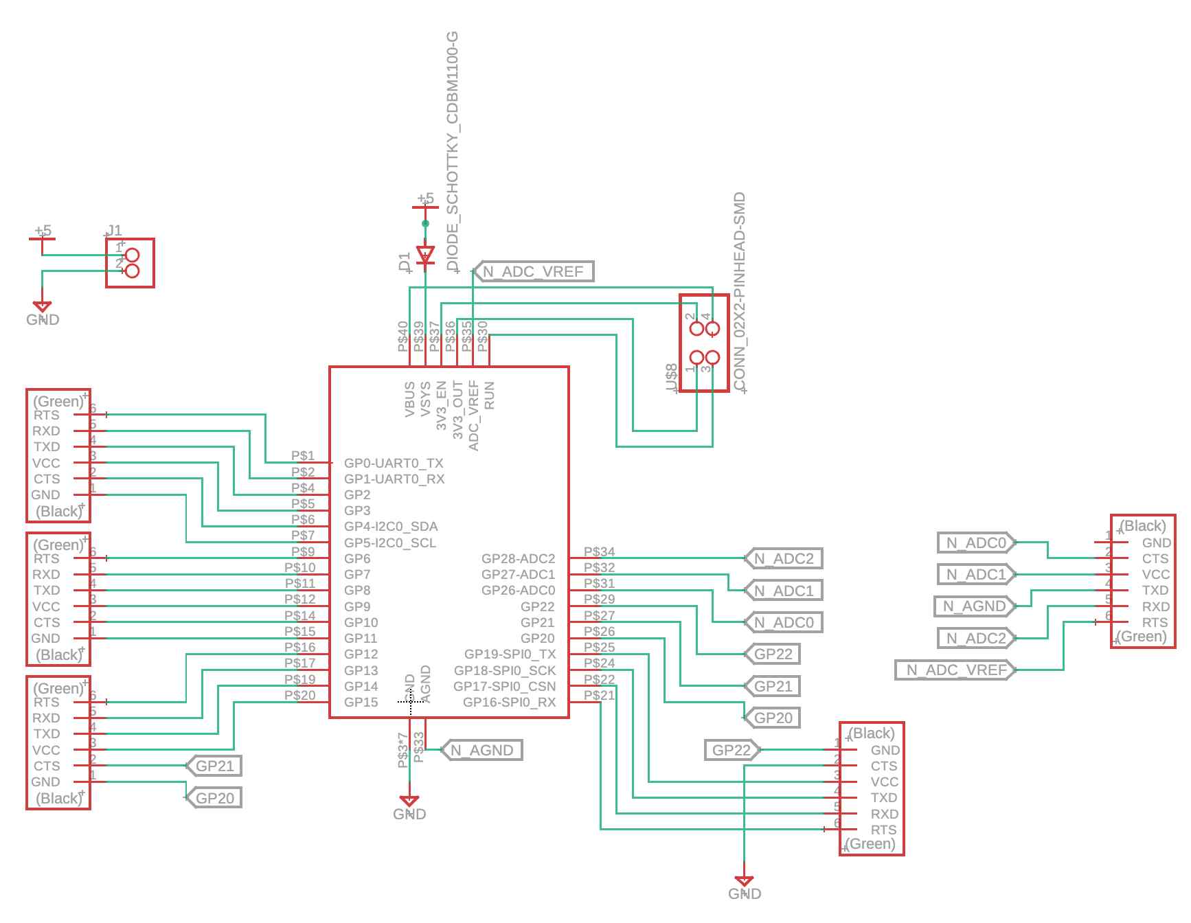
Schematic
I watched some clips from the following tutorial
I had a general idea of how I want to build the circuit and what components I want to add. Initially, I was using the libraries
in fusion and the design files online. I tried to use the design files of Pico-W but didn't know how to link the files to components.
That is when I knew there is a fab library for the class, which was very convenient.
I placed the components and used route naming whenever it helped to make the schematic readable.
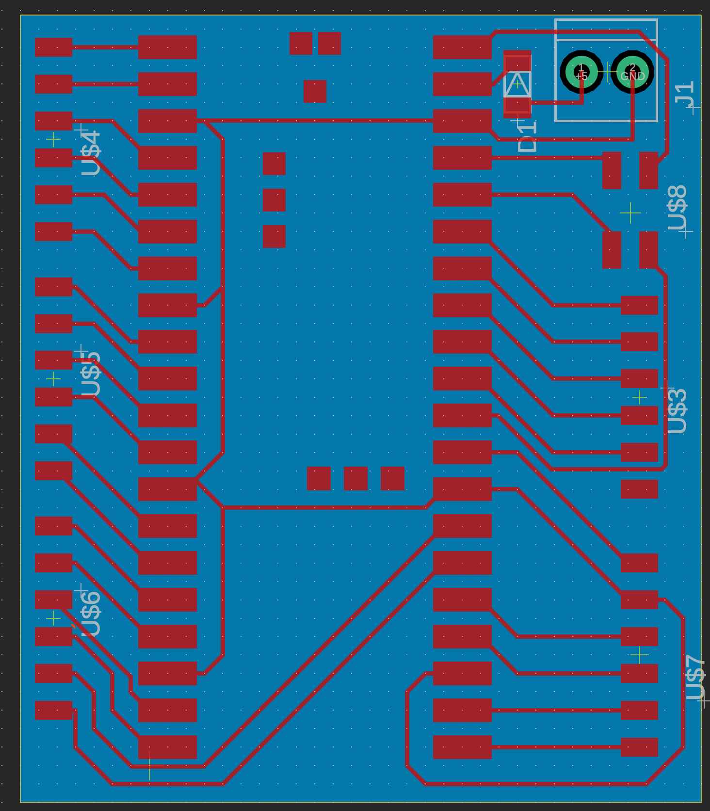
PCB
It felt like a puzzle connecting the components. As someone who used Altium before, I didn't like fusion 360 rouuting as much.
This is possibly because I didn't set up the shortcuts and snapping setting, but placing and routing components was not as smooth
where lines were not optimally placed.
After routing, I ran DRC/ERC check. I used the default setting for clearance and other parameters, which I should check and confirm later.
DRC/ERC
After routing, I ran DRC/ERC check. The setting of the DRC was left to default except for clearance and route thickness. Clearance was 16mil and route thickness was 10mil.
Click to View Design Files
Lecture Notes
Electronic Design Automation (EDA): Programs that allow you to sketch, place components, route the connections simulate and fabricate the boards. First, you setup the design rules of the board, then you can use DRC (design rule check) and ERC (electrical rule check) (to check your work? )
To initially design the board, people draw then use drafting tap to simulate it physically. There are some virtual breadboard
programs that allows you to simulate the program.
When designing, you need to use parts that might not exists in your library. There are libraries where you can import the design files and
create components. Libraries are like: Component Search Engine, Digi-Key, SnapEDA, Ultra Librarian, DesignSpark, library.io
You can simulate electrical circuit using some simulation programs like SPICE (and its variations).
Building circuits, you will need to debug them using test equipments.
Tips
Have more power supply pins to make connected external sensors easier.
You will go back to the schematic to adjust the placement of pins to make routing easier.
Name the routes, Fusion doesn't name the route based on the name of the pin automatically.
Leave enough space for the connector to lay on the board so it's not hanging on air.
Future Work
- When I have more of a complicated circuit, I want to try SPICE. I have used it once before, but I didn't have enough time to explore it well.
- Experiment with other EDAs that offer auto-routing
Assignment Description
Individual Assignments:
- use an EDA tool to design a development board to interact and communicate with an embedded microcontroller
- extra credit: try another design workflow
- extra credit: design a case for it
- extra credit: simulate its operation