Idea
For my final project, I want to build a simple bike computer that fits my needs. Check my final project page for full description, but for this project I want three inputs. Speed with a hall sensor, acceleration with accelerometer, and my GPS location.
PCB Design and Fabrication
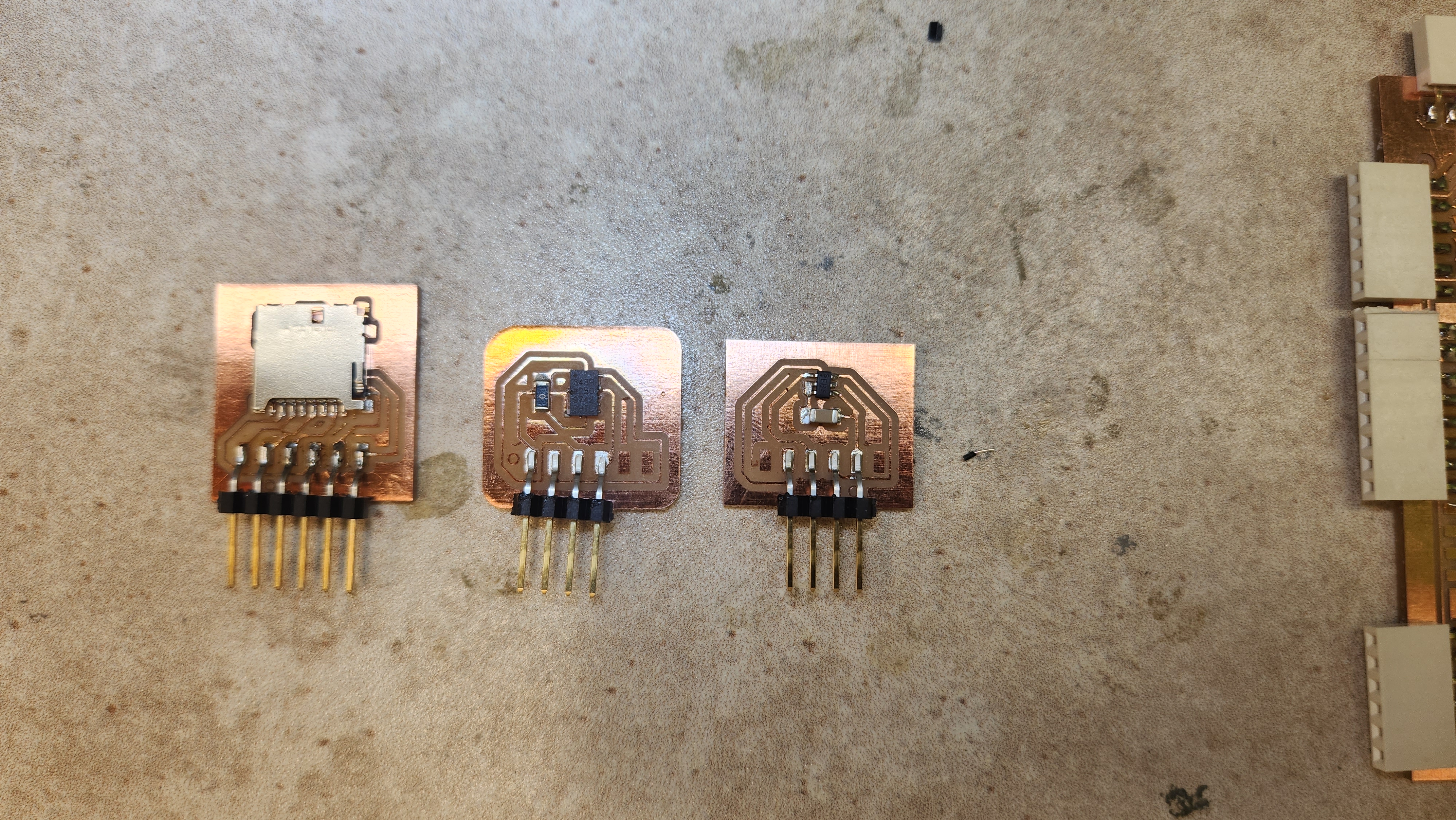
First boards for accelerometer and hall sensor I made
First, I didn't add a pull-up resistor to the hall sensor. Also, it was a bad practice to put two separate boards in one file.


Second, third, fourth, many boards later: Common mistakes
I ran into a lot of bugs that I spent hours fixing them. One is not milling the board right. I cut too deep into the board that the traces were too weak. Another one is while soldering. Solder the accelerometer was tricky because you forget about the upper and lower pins and not give the solder they deserve. I milled a board then I was not getting readings at all, going back I realized that they were not soldered well. After trying to fix that, I put too much solder that now I got devices in all addresses. Going back, I realized I have shorted some connections. Fixing the same board multiple of times, the board started to burn from the heat of the heat gun, where I ended up milling another board. Also, wiring was messing as I used the extension board from the electronic production week, one mistake I did then is having one Vcc pin, which made connecting multiple sensors harder.
Forgot pull up resistors in hall sensor

Messy Wiring

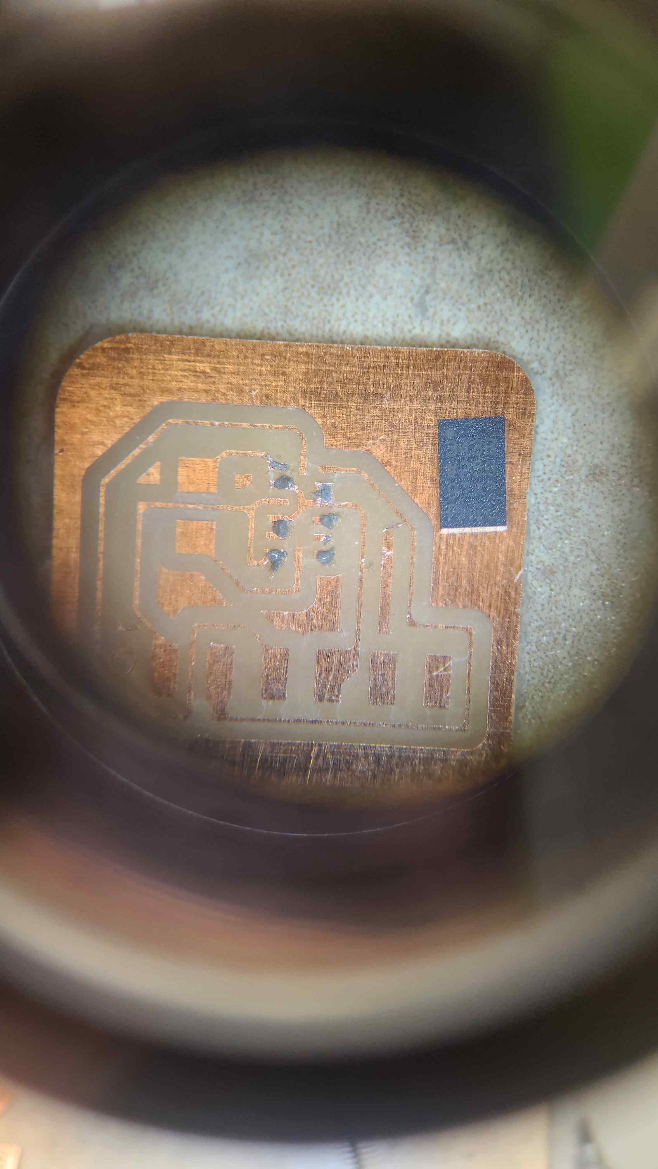
Acceleration Soldering
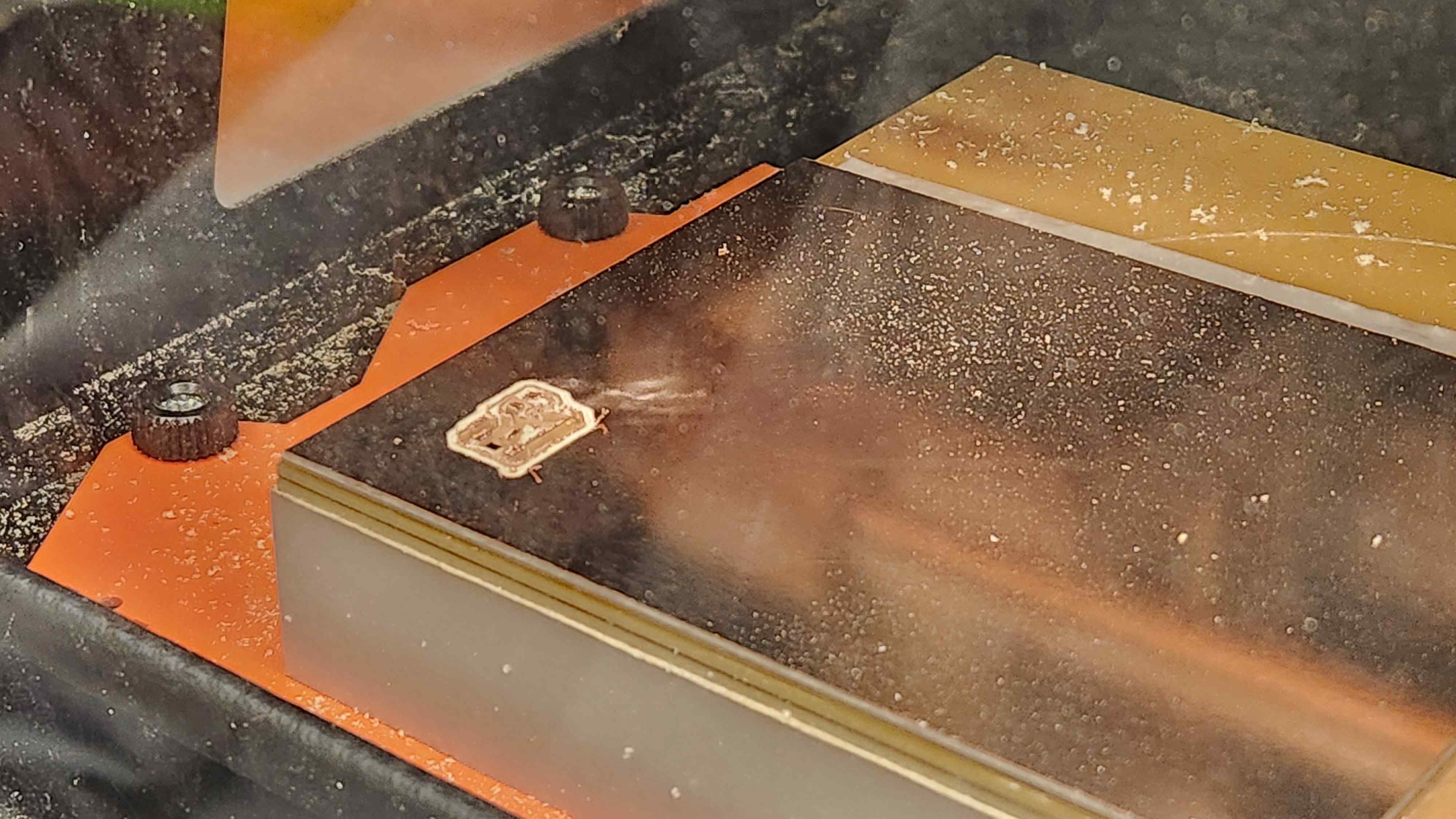
Another Milling Device
As the other mill was busy, I found it a chance to learn how to use the MonoFab device. I appreciated how user-friendly the Other Mill is. One mistake we did is clicking on the b-bit setting accidentally and looking at the depth afterwards, which cut the pcb too deep. Luckily, the mill did not break. After, we did a second try with the correct setting and I got beautiful traces.
Final boards
I moved the pull-up resistors to the main board and connected all I2C devices to the same bus. I used 5K ohm resistors. I was careful about the amount of solder I placed. One technique I used is to put some solder, heat it, make sure it goes where you want to go, then put the piece back carefully with a tweezer, put the heat gun away, wait a bit to let it cool, then you are done.
Link to Accelerometer board
Link to Accelerometer schematic
GPS module
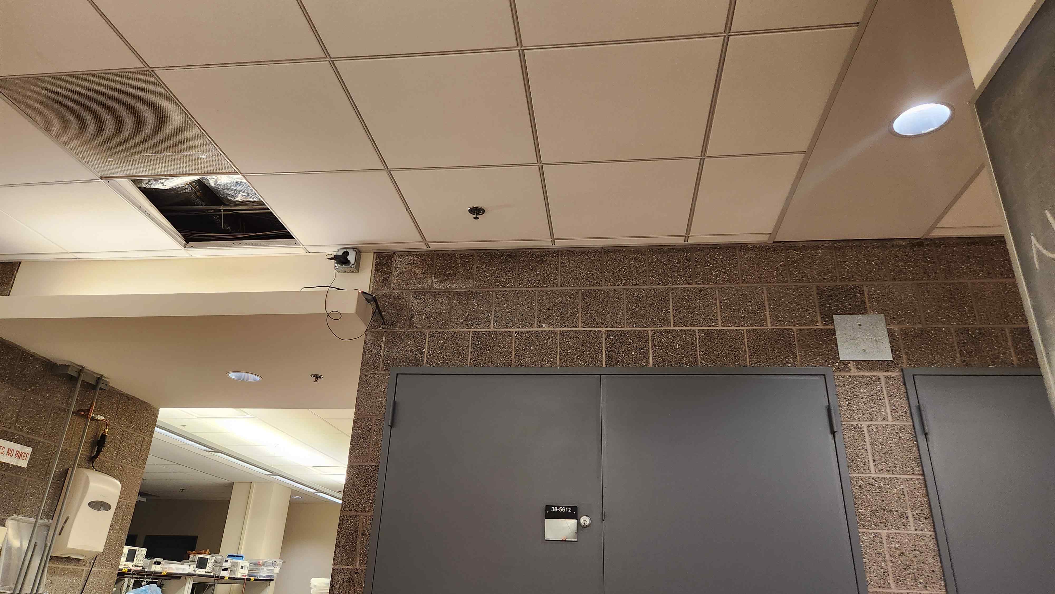
I learned much more about GPS. My phone GPS and the fact it works in buildings was very deceiving. I learned that this module works around an antenna, which the EECS lab got, and outdoor. The way this work is that the GPS module tries to find minimum 4 satellites to create what is call a Fix Point. The GPS module continuously sends GPS sentences, but they don't have information until it finds a fix point.
Lesson learned, make sure you are close to the antenna or have enough open sky for the GPS module. I spend a couple of times back and fourth, while sitting beside the wall where I believed the antenna is, but it could not pick up more than 3 satellites to find the fix point. I went outside my door being 5 meters away from any wall, but I was still in the courtyard surrounded by buildings, it couldn't find more than 3 points. After, I came back to the lab, change the module saw where the antenna is exactly, I sat on the other side of the wall I was sitting beside. Then, it worked and found a fix point in less than 7 minutes.
Also, I made sure I connected Rx-Tx and Tx to Rx, which is a mistake I did at the beginning.
Programming
This step took way longer than expected. First thing I did was to read the data sheet, find what are the addresses that I want to read, then using Wire library to read them. Simple, right? No... There might be layers of the Wire library that I don't understand, which I spent hours debugging with the oscilloscope and forums.
For the accelerometer, I used Adafruit existing library Adafruit_ADXL343 , which worked!
             #include
                #include

                int led = LED_BUILTIN;
                float acc_x = 0;
                float acc_y = 0;
                float acc_z = 0;

                #define ADXL343 0x53
                #define ADXL343_W 0xA6
                #define ADXL343_R 0xA7

                Adafruit_ADXL343 accel = Adafruit_ADXL343(123 , &Wire1);

                void setup_acc()
                {
                  pinMode(led, OUTPUT);
                  Serial.println("Accelerometer Test"); Serial.println("");

                  /* Initialise the sensor */
                  if(!accel.begin(ADXL343))
                  {
                    /* There was a problem detecting the ADXL343 ... check your connections */
                    Serial.println("Ooops, no ADXL343 detected ... Check your wiring!");
                    while(1);
                  }
                  accel.setRange(ADXL343_RANGE_16_G);
                  Serial.println("FINISHED!");
                }

                void acc_meas() {
                  /* Get a new sensor event */
                  sensors_event_t event;
                  accel.getEvent(&event);

                  acc_x = event.acceleration.x;
                  acc_y = event.acceleration.y;
                  acc_z = event.acceleration.z;
                }

                void acc_meas_print() {
                  /* Display the results (acceleration is measured in m/s^2) */
                  Serial.print("Acceleration: ");
                  Serial.print("X: "); Serial.print(acc_x); Serial.print("  ");
                  Serial.print("Y: "); Serial.print(acc_y); Serial.print("  ");
                  Serial.print("Z: "); Serial.print(acc_z); Serial.print("  ");Serial.println("m/s^2 ");
                }
For the hall sensor, after reading registers immediately did not work, I tried looking at previous student work. I found a student using a library Tle493d_a2b6. It worked for one axis, sometimes. It was suddenly stopping from working. I first debugged the connections, then the signal with the oscilloscope, with no clear reason why it did not work. Eventually, after many hours of debugging, I used an existing pcb with hall sensor that working as an analog sensor. This worked well and the code was straightforward.
             #define HALL_PIN A0

             int hall_value;
             void setup_hall() {
               return;
             }

             void hall_meas() {
               hall_value = analogRead(HALL_PIN); //I don't need to map it to any other value.. it'll range between 0 - 4095
             }

             void hall_meas_print() {
               Serial.print("Hall Effect Sensor: ");
               Serial.print(hall_value); Serial.println("unitless/not mapped");
             }
For the GPS module, I found this website that exaplians the sentences the module sends. Be aware when coding that the sentences ID sent had a slightly different prefix.
        #include
        #include
        #include
        #include

        void setup() {
            // initialize both serial ports:
            Serial.begin(9600);
            Serial1.begin(9600);
        }

        void loop() {
            read_gps();

        }
        char inByte, buf[100];
        char *ptr,*ID,*UTC,*latitude,*NS,*longitude,*EW,*fix,*satellites,*dilation,*altitude,*units, *validity;
        uint8_t len = 0;

        // Struct to store each point data

        typedef struct {
        float lat;
        float lon;
        float alt;
        int year;
        int month;
        int day;
        int hrs;
        int mins;
        float secs;
        } gps_p;

        void setup_gps() {
        Serial1.begin(9600);
        }

        gps_p create_gps(float lat, float lon, float alt, int year, int month, int day, int hrs, int mins, float secs) {
        gps_p new_gps;
        new_gps.lat = lat;
        new_gps.lon = lon;
        new_gps.alt = alt;
        new_gps.year = year;
        new_gps.month = month;
        new_gps.day = day;
        new_gps.hrs = hrs;
        new_gps.mins = mins;
        new_gps.secs = secs;
        return new_gps;
        }

        // Function to print the values of a gps_p structure using printf
        void print_gps(const gps_p point) {
        printf("Latitude: %f\n", point.lat);
        printf("Longitude: %f\n", point.lon);
        printf("Altitude: %f\n", point.alt);
        printf("Date: %d-%d-%d", point.year, point.month, point.day);
        printf("Time: %d hours, %d minutes, %f seconds\n", point.hrs, point.mins, point.secs);
        }


        gps_p parse_gps_data(const char *lat, const char *NS, const char *lon, const char *EW, const char *alt, const char *UTC) {

        // parse info
        // parse latitude: ddmm.mmmm
        float lat_deg, lat_min;
        sscanf(lat, "%2f%5f", &lat_deg, &lat_min);
        float re_lat = lat_deg + lat_min/60;
        re_lat = (*NS == 'N') ? re_lat : -re_lat;

        // parse longitude: dddmm.mmmm
        float lon_deg, lon_min;
        sscanf(lon, "%3f%5f", &lon_deg, &lon_min);
        float re_lon = lon_deg + lon_min/60;
        re_lon = (*EW == 'E') ? re_lon : -re_lon;

        // parse altitude: float
        float re_alt = atof(alt);

        // parse time UTC: hhmmss.sss
        int hrs, mins;
        float secs;
        sscanf(UTC, "%2d%2d%6f", &hrs, &mins, &secs);
        int day = 0;
        int month = 0;
        int year = 0;

        gps_p point = create_gps(re_lat, re_lon, re_alt, year, month, day, hrs, mins, secs);
        return point;
        }


        gps_p parse_gps_messages(char *buf) {
        // Exmple Valid Message with the data wanted:
        // Format: $GNRMC, utc, pos status, lat, lat dir, lon, lon dir, speed Kn, track true, date, mag var, var dir, mode ind
        // Format: $GNRMC, hhmmss.ss, A/V, DDmm.mm, N/S, DDDmm.mm, E/W, float, float, ddmmyy, float, E/W, A
        // GNRMC,210546.000,A,4221.6641,N,07105.5411,W,0.00,0.00,151223,,,A*62

        // 16:05:45.512 -> GPTXT,01,01,01,ANTENNA OK*35
        // 16:05:45.998 -> GNGGA,210546.000,4221.6641,N,07105.5411,W,1,05,1.5,5.1,M,0.0,M,,*63
        // 16:05:46.063 -> GNGLL,4221.6641,N,07105.5411,W,210546.000,A,A*53
        // 16:05:46.095 -> GPGSA,A,3,27,21,07,16,08,,,,,,,,2.7,1.5,2.3*3C
        // 16:05:42.144 -> BDGSA,A,3,,,,,,,,,,,,,2.7,1.5,2.3*23
        // 16:05:46.191 -> GPGSV,2,1,08,02,09,165,,07,45,308,28,08,69,193,26,09,,,22*4D
        // 16:05:46.350 -> BDGSV,1,1,00*68
        // 16:05:46.350 -> GNRMC,210546.000,A,4221.6641,N,07105.5411,W,0.00,0.00,151223,,,A*62
        // 16:05:46.415 -> GNVTG,0.00,T,,M,0.00,N,0.00,K,A*23
        // 16:05:46.478 -> GNZDA,210546.000,15,12,2023,00,00*48

        if (strncmp(buf,"GNGAA",5) == 0) { // check for fix data
            ID = strtok_r(buf,",",&ptr);
            UTC = strtok_r(NULL,",",&ptr);
            if (buf[10+UTC-buf] == ',') { // check for empty latitude
            printf("%s: no fix\n",UTC);
            } else {
            latitude = strtok_r(NULL,",",&ptr);
            NS = strtok_r(NULL,",",&ptr);
            longitude = strtok_r(NULL,",",&ptr);
            EW = strtok_r(NULL,",",&ptr);
            fix = strtok_r(NULL,",",&ptr);
            satellites = strtok_r(NULL,",",&ptr);
            dilation = strtok_r(NULL,",",&ptr);
            altitude = strtok_r(NULL,",",&ptr);
            units = strtok_r(NULL,",",&ptr);
            printf("UTC time: %s, ",UTC);
            printf("Latitude: %s ",latitude);
            printf("%s, ",NS);
            printf("Longitude: %s ",longitude);
            printf("%s, ",EW);
            printf("Satellites: %s, ",satellites);
            printf("Altitude: %s ",altitude);
            printf("%s\n",units);
            return parse_gps_data(latitude, NS, longitude, EW, altitude, URC);
            }
        }
        }

        char msg[100];

        bool read_gps() {
        // read from port 1, send to port 0:
        if (Serial1.available()) {
            inByte = Serial1.read();
            Serial.print(inByte);
            if (inByte == '$') {
            buf[len] = '\0'; // Null-terminate the string
            Serial.print("Buffer: ");
            Serial.println(buf);
            gps_p rec_point = parse_gps_messages(buf); //RETURN THIS POINT OR MAKE IT GLOBAL
            strcpy(msg, buf);
            memset(buf, 0, sizeof(buf)); // Clear the buffer
            len = 0;
            return true;
            } else {
            buf[len++] = inByte;
            if (len >= sizeof(buf)) {
                // Buffer overflow protection, reset the buffer
                memset(buf, 0, sizeof(buf));
                len = 0;
            }
            }
        }
        return false;
        }
Lecture Notes
Peripherals Methods
1. Registers: store input to a register and write output to one.
2. Comparators: compare two values and output a result quickly.
3. ADC: write analog readings and convert it to digital. Higher resolution = slower readings
Clocks
1. RC clocks 2. Possibly using external clocks
Devices
1. Button switch
2. Motion: sense the change of heat.
3. Motion: Doppler shift Sensor: sense motion. Can be behind RF passing walls.
4. Distance: Sonar sensors: absolute distances. Tilted objects will mess up readings. You need good objects that reflect signal back.
5. Distance: Optical: measures light and its reflection to measure distance. easiest way to get a breakout board
6. Magnetic: Hall sensor: apply voltage and measure transverse voltage through ADC. It is a vector measurement, side matters. Applications like joytick or lid status
7. Temperature: thermestor = resistor which resistance changes based on temperature. Types: NTC: lower temps and RTV: higher temps. The way to read this by using a bridge
because a voltage divider does not cover the whole range. Using the bridge you can measure the difference of change that is amplified
8. Light: phototransistors: the current needs some gain. You can handle the environment light change and noise by synchronous detection.
9. Light: RGB reading
10. Acceleratormer: talks in i2c.
11: sound: MEMS microphone: analog and use ADC
12. Sound: fully digital microphones
13. Capacitance sensor: Loading. To reduce noise you charge it periodically.Synchronous undersampling is interesting, but it goes through room ground.
Put elastic -> force sensor. So many applications [vid 50:10]
14. Vibration
15. Force: not reliable and messy measurements. Strain gage are better
16. ID: very interesting. can I make an ID bracelet?
17. Camera: modules are big, but there exists some library. Do image processing with OpenCV possibly. WebRTc is to use websites to talk to webcamera and
use javascript to code.
Info
Sampling: Read the data multiple of times to reduce the error. error is reduces by the sqrt(samplings) Reflow: technique to solder small parts like accelerometer.
Assignment Description
Individual Assignments:
- measure something: add a sensor to a microcontroller board that you have designed and read it
Group Assignment:
- probe an input device's analog levels and digital signals