Idea
For my final project, I want to build a simple bike computer that fits my needs. Check my final project page for full description, but for this project I want to use two OLED screens, and an SD card to store and display the output.
SD reader board
The first board I made, I forgot about the clearance for the SD card to be inserted, and the footprint didn't clearly indicate where that is, this I accidentally designed a board where you cannot insert a micro SD card.
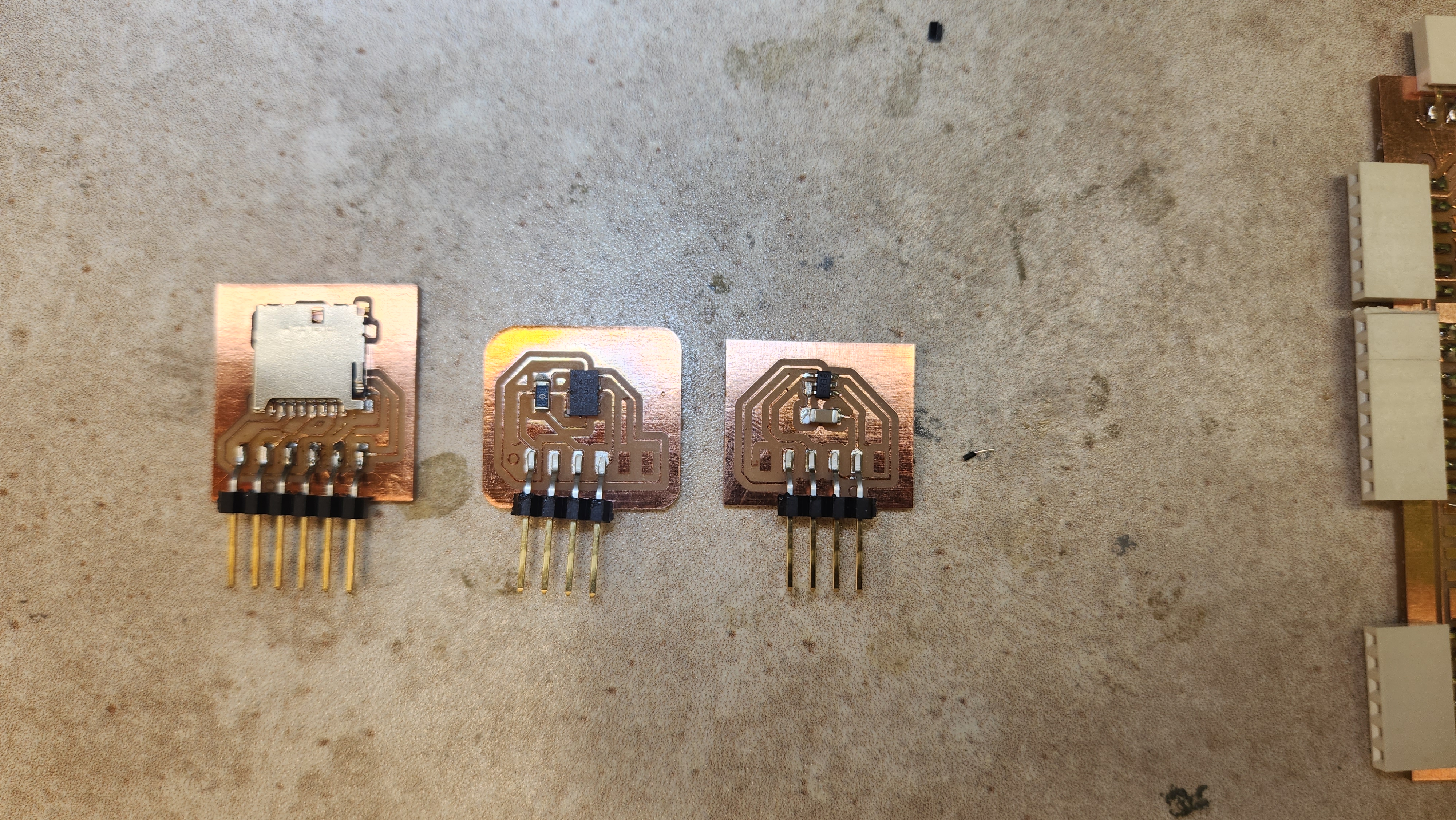
While fixing that, I figured I can try talking to an SD card and write the code meanwhile. I used an SD card module. It has a voltage regulator (it is designed to accept all the way to 5V) and a shifter besides the SD insert. That did not work, where the code did not find the module. Initially, I thought something is going on with not using the default pins and using SPI1. After so much debugging, we realized that the voltage regulator signal was noisy, where the board cannot function properly. The moment we connected the V wire to 5 volts, it works.
LCD screen
Be aware if you are using pico W and LCD screen with eSPI. I was very optimistic about this, since I used the same type of screen in my freshman year and looked at 6.08 website. I set up the User Setup.h file as needed for my circuit, but it did not work. First mistake I did was plugging in the screen through my board header backwards. Before, I was seeing a black screen, after, I see a white screen. It still didn't apply the code. We discovered a short between the Vcc and SDA line at some point, still did not work after fixing it. Using example setup online for the pico W and after so much debugging, we couldn't get it to work with arduino. We know that the screen works for sure, as someone tried it with micropython, and it works. I tried both SPI0 and SPI1, and changed the setup and tweaked around so many parameters, it still did not work. The User Setup file is the following for reference. However, we moved to using OLED.
             //                            USER DEFINED SETTINGS
             //   Set driver type, fonts to be loaded, pins used and SPI control method etc.
             //
             //   See the User_Setup_Select.h file if you wish to be able to define multiple
             //   setups and then easily select which setup file is used by the compiler.
             //
             //   If this file is edited correctly then all the library example sketches should
             //   run without the need to make any more changes for a particular hardware setup!
             //   Note that some sketches are designed for a particular TFT pixel width/height

             // User defined information reported by "Read_User_Setup" test & diagnostics example
             #define USER_SETUP_INFO "User_Setup"

             // Define to disable all #warnings in library (can be put in User_Setup_Select.h)
             //#define DISABLE_ALL_LIBRARY_WARNINGS

             // ##################################################################################
             //
             // Section 1. Call up the right driver file and any options for it
             //
             // ##################################################################################

             // Define STM32 to invoke optimised processor support (only for STM32)
             //#define STM32

             // Defining the STM32 board allows the library to optimise the performance
             // for UNO compatible "MCUfriend" style shields
             //#define NUCLEO_64_TFT
             //#define NUCLEO_144_TFT

             // STM32 8-bit parallel only:
             // If STN32 Port A or B pins 0-7 are used for 8-bit parallel data bus bits 0-7
             // then this will improve rendering performance by a factor of ~8x
             //#define STM_PORTA_DATA_BUS
             //#define STM_PORTB_DATA_BUS

             // Tell the library to use parallel mode (otherwise SPI is assumed)
             //#define TFT_PARALLEL_8_BIT
             //#defined TFT_PARALLEL_16_BIT // **** 16-bit parallel ONLY for RP2040 processor ****

             // Display type -  only define if RPi display
             //#define RPI_DISPLAY_TYPE // 20MHz maximum SPI

             // Only define one driver, the other ones must be commented out
             //#define ILI9341_DRIVER       // Generic driver for common displays
             //#define ILI9341_2_DRIVER     // Alternative ILI9341 driver, see https://github.com/Bodmer/TFT_eSPI/issues/1172
             #define ST7735_DRIVER      // Define additional parameters below for this display
             //#define ILI9163_DRIVER     // Define additional parameters below for this display
             //#define S6D02A1_DRIVER
             //#define RPI_ILI9486_DRIVER // 20MHz maximum SPI
             //#define HX8357D_DRIVER
             //#define ILI9481_DRIVER
             //#define ILI9486_DRIVER
             //#define ILI9488_DRIVER     // WARNING: Do not connect ILI9488 display SDO to MISO if other devices share the SPI bus (TFT SDO does NOT tristate when CS is high)
             //#define ST7789_DRIVER      // Full configuration option, define additional parameters below for this display
             //#define ST7789_2_DRIVER    // Minimal configuration option, define additional parameters below for this display
             //#define R61581_DRIVER
             //#define RM68140_DRIVER
             //#define ST7796_DRIVER
             //#define SSD1351_DRIVER
             //#define SSD1963_480_DRIVER
             //#define SSD1963_800_DRIVER
             //#define SSD1963_800ALT_DRIVER
             //#define ILI9225_DRIVER
             //#define GC9A01_DRIVER

             // Some displays support SPI reads via the MISO pin, other displays have a single
             // bi-directional SDA pin and the library will try to read this via the MOSI line.
             // To use the SDA line for reading data from the TFT uncomment the following line:

             //#define TFT_SDA_READ      // This option is for ESP32 ONLY, tested with ST7789 and GC9A01 display only

             // For ST7735, ST7789 and ILI9341 ONLY, define the colour order IF the blue and red are swapped on your display
             // Try ONE option at a time to find the correct colour order for your display

             //  #define TFT_RGB_ORDER TFT_RGB  // Colour order Red-Green-Blue
             //  #define TFT_RGB_ORDER TFT_BGR  // Colour order Blue-Green-Red

             // For M5Stack ESP32 module with integrated ILI9341 display ONLY, remove // in line below

             // #define M5STACK

             // For ST7789, ST7735, ILI9163 and GC9A01 ONLY, define the pixel width and height in portrait orientation
             // #define TFT_WIDTH  80
              #define TFT_WIDTH  128
             // #define TFT_WIDTH  172 // ST7789 172 x 320
             // #define TFT_WIDTH  170 // ST7789 170 x 320
             // #define TFT_WIDTH  240 // ST7789 240 x 240 and 240 x 320
              #define TFT_HEIGHT 160
             // #define TFT_HEIGHT 128
             // #define TFT_HEIGHT 240 // ST7789 240 x 240
             // #define TFT_HEIGHT 320 // ST7789 240 x 320
             // #define TFT_HEIGHT 240 // GC9A01 240 x 240

             // For ST7735 ONLY, define the type of display, originally this was based on the
             // colour of the tab on the screen protector film but this is not always true, so try
             // out the different options below if the screen does not display graphics correctly,
             // e.g. colours wrong, mirror images, or stray pixels at the edges.
             // Comment out ALL BUT ONE of these options for a ST7735 display driver, save this
             // this User_Setup file, then rebuild and upload the sketch to the board again:

             // #define ST7735_INITB
             // #define ST7735_GREENTAB
             // #define ST7735_GREENTAB2
             // #define ST7735_GREENTAB3
             // #define ST7735_GREENTAB128    // For 128 x 128 display
             // #define ST7735_GREENTAB160x80 // For 160 x 80 display (BGR, inverted, 26 offset)
             // #define ST7735_ROBOTLCD       // For some RobotLCD Arduino shields (128x160, BGR, https://docs.arduino.cc/retired/getting-started-guides/TFT)
             #define ST7735_REDTAB
             // #define ST7735_BLACKTAB
             // #define ST7735_REDTAB160x80   // For 160 x 80 display with 24 pixel offset

             // If colours are inverted (white shows as black) then uncomment one of the next
             // 2 lines try both options, one of the options should correct the inversion.

             // #define TFT_INVERSION_ON
             // #define TFT_INVERSION_OFF


             // ##################################################################################
             //
             // Section 2. Define the pins that are used to interface with the display here
             //
             // ##################################################################################

             // If a backlight control signal is available then define the TFT_BL pin in Section 2
             // below. The backlight will be turned ON when tft.begin() is called, but the library
             // needs to know if the LEDs are ON with the pin HIGH or LOW. If the LEDs are to be
             // driven with a PWM signal or turned OFF/ON then this must be handled by the user
             // sketch. e.g. with digitalWrite(TFT_BL, LOW);

             // #define TFT_BL   32            // LED back-light control pin
             // #define TFT_BACKLIGHT_ON HIGH  // Level to turn ON back-light (HIGH or LOW)


             // We must use hardware SPI, a minimum of 3 GPIO pins is needed.
             // Typical setup for ESP8266 NodeMCU ESP-12 is :
             //
             // Display SDO/MISO  to NodeMCU pin D6 (or leave disconnected if not reading TFT)
             // Display LED       to NodeMCU pin VIN (or 5V, see below)
             // Display SCK       to NodeMCU pin D5
             // Display SDI/MOSI  to NodeMCU pin D7
             // Display DC (RS/AO)to NodeMCU pin D3
             // Display RESET     to NodeMCU pin D4 (or RST, see below)
             // Display CS        to NodeMCU pin D8 (or GND, see below)
             // Display GND       to NodeMCU pin GND (0V)
             // Display VCC       to NodeMCU 5V or 3.3V
             //
             // The TFT RESET pin can be connected to the NodeMCU RST pin or 3.3V to free up a control pin
             //
             // The DC (Data Command) pin may be labelled AO or RS (Register Select)
             //
             // With some displays such as the ILI9341 the TFT CS pin can be connected to GND if no more
             // SPI devices (e.g. an SD Card) are connected, in this case comment out the #define TFT_CS
             // line below so it is NOT defined. Other displays such at the ST7735 require the TFT CS pin
             // to be toggled during setup, so in these cases the TFT_CS line must be defined and connected.
             //
             // The NodeMCU D0 pin can be used for RST
             //
             //
             // Note: only some versions of the NodeMCU provide the USB 5V on the VIN pin
             // If 5V is not available at a pin you can use 3.3V but backlight brightness
             // will be lower.


             // ###### EDIT THE PIN NUMBERS IN THE LINES FOLLOWING TO SUIT YOUR ESP8266 SETUP ######

             // #define TFT_MISO 16 //GP16 , pin 21
             // #define TFT_MOSI 19 //GP19, pin 25
             // #define TFT_SCLK 18 //GP18, pin 24
             #define TFT_CS   17  // GP17, pin 22 - Chip select control pin
             #define TFT_DC   15  // GP15, pin 20 Data Command control pin
             #define TFT_RST  14  // GP14, pin 19 Reset pin (could connect to RST pin)

             // For NodeMCU - use pin numbers in the form PIN_Dx where Dx is the NodeMCU pin designation
             // #define TFT_MISO  PIN_D6  // Automatically assigned with ESP8266 if not defined
             // #define TFT_MOSI  PIN_D7  // Automatically assigned with ESP8266 if not defined
             // #define TFT_SCLK  PIN_D5  // Automatically assigned with ESP8266 if not defined

             // #define TFT_CS    PIN_D8  // Chip select control pin D8
             // #define TFT_DC    PIN_D3  // Data Command control pin
             // #define TFT_RST   PIN_D4  // Reset pin (could connect to NodeMCU RST, see next line)
             //#define TFT_RST  -1     // Set TFT_RST to -1 if the display RESET is connected to NodeMCU RST or 3.3V


             //#define TFT_BL PIN_D1  // LED back-light (only for ST7789 with backlight control pin)

             //#define TOUCH_CS PIN_D2     // Chip select pin (T_CS) of touch screen

             //#define TFT_WR PIN_D2       // Write strobe for modified Raspberry Pi TFT only


             // ######  FOR ESP8266 OVERLAP MODE EDIT THE PIN NUMBERS IN THE FOLLOWING LINES  ######

             // Overlap mode shares the ESP8266 FLASH SPI bus with the TFT so has a performance impact
             // but saves pins for other functions. It is best not to connect MISO as some displays
             // do not tristate that line when chip select is high!
             // Note: Only one SPI device can share the FLASH SPI lines, so a SPI touch controller
             // cannot be connected as well to the same SPI signals.
             // On NodeMCU 1.0 SD0=MISO, SD1=MOSI, CLK=SCLK to connect to TFT in overlap mode
             // On NodeMCU V3  S0 =MISO, S1 =MOSI, S2 =SCLK
             // In ESP8266 overlap mode the following must be defined

             //#define TFT_SPI_OVERLAP

             // In ESP8266 overlap mode the TFT chip select MUST connect to pin D3
             //#define TFT_CS   PIN_D3
             //#define TFT_DC   PIN_D5  // Data Command control pin
             //#define TFT_RST  PIN_D4  // Reset pin (could connect to NodeMCU RST, see next line)
             //#define TFT_RST  -1  // Set TFT_RST to -1 if the display RESET is connected to NodeMCU RST or 3.3V


             // ###### EDIT THE PIN NUMBERS IN THE LINES FOLLOWING TO SUIT YOUR ESP32 SETUP   ######

             // For ESP32 Dev board (only tested with ILI9341 display)
             // The hardware SPI can be mapped to any pins

             //#define TFT_MISO 19
             //#define TFT_MOSI 23
             //#define TFT_SCLK 18
             //#define TFT_CS   15  // Chip select control pin
             //#define TFT_DC    2  // Data Command control pin
             //#define TFT_RST   4  // Reset pin (could connect to RST pin)
             //#define TFT_RST  -1  // Set TFT_RST to -1 if display RESET is connected to ESP32 board RST

             // For ESP32 Dev board (only tested with GC9A01 display)
             // The hardware SPI can be mapped to any pins

             //#define TFT_MOSI 15 // In some display driver board, it might be written as "SDA" and so on.
             //#define TFT_SCLK 14
             //#define TFT_CS   5  // Chip select control pin
             //#define TFT_DC   27  // Data Command control pin
             //#define TFT_RST  33  // Reset pin (could connect to Arduino RESET pin)
             //#define TFT_BL   22  // LED back-light

             //#define TOUCH_CS 21     // Chip select pin (T_CS) of touch screen

             //#define TFT_WR 22    // Write strobe for modified Raspberry Pi TFT only

             // For the M5Stack module use these #define lines
             //#define TFT_MISO 19
             //#define TFT_MOSI 23
             //#define TFT_SCLK 18
             //#define TFT_CS   14  // Chip select control pin
             //#define TFT_DC   27  // Data Command control pin
             //#define TFT_RST  33  // Reset pin (could connect to Arduino RESET pin)
             //#define TFT_BL   32  // LED back-light (required for M5Stack)

             // ######       EDIT THE PINs BELOW TO SUIT YOUR ESP32 PARALLEL TFT SETUP        ######

             // The library supports 8-bit parallel TFTs with the ESP32, the pin
             // selection below is compatible with ESP32 boards in UNO format.
             // Wemos D32 boards need to be modified, see diagram in Tools folder.
             // Only ILI9481 and ILI9341 based displays have been tested!

             // Parallel bus is only supported for the STM32 and ESP32
             // Example below is for ESP32 Parallel interface with UNO displays

             // Tell the library to use 8-bit parallel mode (otherwise SPI is assumed)
             //#define TFT_PARALLEL_8_BIT

             // The ESP32 and TFT the pins used for testing are:
             //#define TFT_CS   33  // Chip select control pin (library pulls permanently low
             //#define TFT_DC   15  // Data Command control pin - must use a pin in the range 0-31
             //#define TFT_RST  32  // Reset pin, toggles on startup

             //#define TFT_WR    4  // Write strobe control pin - must use a pin in the range 0-31
             //#define TFT_RD    2  // Read strobe control pin

             //#define TFT_D0   12  // Must use pins in the range 0-31 for the data bus
             //#define TFT_D1   13  // so a single register write sets/clears all bits.
             //#define TFT_D2   26  // Pins can be randomly assigned, this does not affect
             //#define TFT_D3   25  // TFT screen update performance.
             //#define TFT_D4   17
             //#define TFT_D5   16
             //#define TFT_D6   27
             //#define TFT_D7   14

             // ######       EDIT THE PINs BELOW TO SUIT YOUR STM32 SPI TFT SETUP        ######

             // The TFT can be connected to SPI port 1 or 2
             //#define TFT_SPI_PORT 1 // SPI port 1 maximum clock rate is 55MHz
             //#define TFT_MOSI PA7
             //#define TFT_MISO PA6
             //#define TFT_SCLK PA5

             //#define TFT_SPI_PORT 2 // SPI port 2 maximum clock rate is 27MHz
             //#define TFT_MOSI PB15
             //#define TFT_MISO PB14
             //#define TFT_SCLK PB13

             // Can use Ardiuno pin references, arbitrary allocation, TFT_eSPI controls chip select
             //#define TFT_CS   D5 // Chip select control pin to TFT CS
             //#define TFT_DC   D6 // Data Command control pin to TFT DC (may be labelled RS = Register Select)
             //#define TFT_RST  D7 // Reset pin to TFT RST (or RESET)
             // OR alternatively, we can use STM32 port reference names PXnn
             //#define TFT_CS   PE11 // Nucleo-F767ZI equivalent of D5
             //#define TFT_DC   PE9  // Nucleo-F767ZI equivalent of D6
             //#define TFT_RST  PF13 // Nucleo-F767ZI equivalent of D7

             //#define TFT_RST  -1   // Set TFT_RST to -1 if the display RESET is connected to processor reset
                                     // Use an Arduino pin for initial testing as connecting to processor reset
                                     // may not work (pulse too short at power up?)

             // ##################################################################################
             //
             // Section 3. Define the fonts that are to be used here
             //
             // ##################################################################################

             // Comment out the #defines below with // to stop that font being loaded
             // The ESP8366 and ESP32 have plenty of memory so commenting out fonts is not
             // normally necessary. If all fonts are loaded the extra FLASH space required is
             // about 17Kbytes. To save FLASH space only enable the fonts you need!

             #define LOAD_GLCD   // Font 1. Original Adafruit 8 pixel font needs ~1820 bytes in FLASH
             // #define LOAD_FONT2  // Font 2. Small 16 pixel high font, needs ~3534 bytes in FLASH, 96 characters
             // #define LOAD_FONT4  // Font 4. Medium 26 pixel high font, needs ~5848 bytes in FLASH, 96 characters
             // #define LOAD_FONT6  // Font 6. Large 48 pixel font, needs ~2666 bytes in FLASH, only characters 1234567890:-.apm
             // #define LOAD_FONT7  // Font 7. 7 segment 48 pixel font, needs ~2438 bytes in FLASH, only characters 1234567890:-.
             // #define LOAD_FONT8  // Font 8. Large 75 pixel font needs ~3256 bytes in FLASH, only characters 1234567890:-.
             //#define LOAD_FONT8N // Font 8. Alternative to Font 8 above, slightly narrower, so 3 digits fit a 160 pixel TFT
             // #define LOAD_GFXFF  // FreeFonts. Include access to the 48 Adafruit_GFX free fonts FF1 to FF48 and custom fonts

             // Comment out the #define below to stop the SPIFFS filing system and smooth font code being loaded
             // this will save ~20kbytes of FLASH
             #define SMOOTH_FONT


             // ##################################################################################
             //
             // Section 4. Other options
             //
             // ##################################################################################

             // For RP2040 processor and SPI displays, uncomment the following line to use the PIO interface.
             //#define RP2040_PIO_SPI // Leave commented out to use standard RP2040 SPI port interface

             // For RP2040 processor and 8 or 16-bit parallel displays:
             // The parallel interface write cycle period is derived from a division of the CPU clock
             // speed so scales with the processor clock. This means that the divider ratio may need
             // to be increased when overclocking. It may also need to be adjusted dependant on the
             // display controller type (ILI94341, HX8357C etc.). If RP2040_PIO_CLK_DIV is not defined
             // the library will set default values which may not suit your display.
             // The display controller data sheet will specify the minimum write cycle period. The
             // controllers often work reliably for shorter periods, however if the period is too short
             // the display may not initialise or graphics will become corrupted.
             // PIO write cycle frequency = (CPU clock/(4 * RP2040_PIO_CLK_DIV))
             //#define RP2040_PIO_CLK_DIV 1 // 32ns write cycle at 125MHz CPU clock
             //#define RP2040_PIO_CLK_DIV 2 // 64ns write cycle at 125MHz CPU clock
             //#define RP2040_PIO_CLK_DIV 3 // 96ns write cycle at 125MHz CPU clock

             // For the RP2040 processor define the SPI port channel used (default 0 if undefined)
             #define TFT_SPI_PORT 0 // Set to 0 if SPI0 pins are used, or 1 if spi1 pins used

             // For the STM32 processor define the SPI port channel used (default 1 if undefined)
             //#define TFT_SPI_PORT 2 // Set to 1 for SPI port 1, or 2 for SPI port 2

             // Define the SPI clock frequency, this affects the graphics rendering speed. Too
             // fast and the TFT driver will not keep up and display corruption appears.
             // With an ILI9341 display 40MHz works OK, 80MHz sometimes fails
             // With a ST7735 display more than 27MHz may not work (spurious pixels and lines)
             // With an ILI9163 display 27 MHz works OK.

             // #define SPI_FREQUENCY   1000000
             // #define SPI_FREQUENCY   5000000
             // #define SPI_FREQUENCY  10000000
              #define SPI_FREQUENCY  20000000
             //#define SPI_FREQUENCY  27000000
             // #define SPI_FREQUENCY  40000000
             // #define SPI_FREQUENCY  55000000 // STM32 SPI1 only (SPI2 maximum is 27MHz)
             // #define SPI_FREQUENCY  80000000

             // Optional reduced SPI frequency for reading TFT
             #define SPI_READ_FREQUENCY  20000000

             // The XPT2046 requires a lower SPI clock rate of 2.5MHz so we define that here:
             #define SPI_TOUCH_FREQUENCY  2500000

             // The ESP32 has 2 free SPI ports i.e. VSPI and HSPI, the VSPI is the default.
             // If the VSPI port is in use and pins are not accessible (e.g. TTGO T-Beam)
             // then uncomment the following line:
             //#define USE_HSPI_PORT

             // Comment out the following #define if "SPI Transactions" do not need to be
             // supported. When commented out the code size will be smaller and sketches will
             // run slightly faster, so leave it commented out unless you need it!

             // Transaction support is needed to work with SD library but not needed with TFT_SdFat
             // Transaction support is required if other SPI devices are connected.

             // Transactions are automatically enabled by the library for an ESP32 (to use HAL mutex)
             // so changing it here has no effect

             // #define SUPPORT_TRANSACTIONS
OLED SSD1306 Screen
Since I am using the two screens, I had to change the resistor placement in the back of the OLED to change the address. It was very quick implementation, as I wired to the existing I2C bus I have.
                /**************************************************************************
                This is an example for our Monochrome OLEDs based on SSD1306 drivers

                Pick one up today in the adafruit shop!
                ------> http://www.adafruit.com/category/63_98

                This example is for a 128x32 pixel display using I2C to communicate
                3 pins are required to interface (two I2C and one reset).

                Adafruit invests time and resources providing this open
                source code, please support Adafruit and open-source
                hardware by purchasing products from Adafruit!

                Written by Limor Fried/Ladyada for Adafruit Industries,
                with contributions from the open source community.
                BSD license, check license.txt for more information
                All text above, and the splash screen below must be
                included in any redistribution.
                **************************************************************************/

               #include
               #include

               #define SCREEN_WIDTH 128 // OLED display width, in pixels
               #define SCREEN_HEIGHT 32 // OLED display height, in pixels

               // Declaration for an SSD1306 display connected to I2C (SDA, SCL pins)
               // The pins for I2C are defined by the Wire-library.
               // On an arduino UNO:       A4(SDA), A5(SCL)
               // On an arduino MEGA 2560: 20(SDA), 21(SCL)
               // On an arduino LEONARDO:   2(SDA),  3(SCL), ...
               #define OLED_RESET     -1 // Reset pin # (or -1 if sharing Arduino reset pin)
               #define SCREEN_ADDRESS 0x3C ///< See datasheet for Address; 0x3D for 128x64, 0x3C for 128x32
               Adafruit_SSD1306 display(SCREEN_WIDTH, SCREEN_HEIGHT, &Wire1, OLED_RESET);

               #define NUMFLAKES     10 // Number of snowflakes in the animation example

               #define LOGO_HEIGHT   16
               #define LOGO_WIDTH    16
               static const unsigned char PROGMEM logo_bmp[] =
               { 0b00000000, 0b11000000,
                 0b00000001, 0b11000000,
                 0b00000001, 0b11000000,
                 0b00000011, 0b11100000,
                 0b11110011, 0b11100000,
                 0b11111110, 0b11111000,
                 0b01111110, 0b11111111,
                 0b00110011, 0b10011111,
                 0b00011111, 0b11111100,
                 0b00001101, 0b01110000,
                 0b00011011, 0b10100000,
                 0b00111111, 0b11100000,
                 0b00111111, 0b11110000,
                 0b01111100, 0b11110000,
                 0b01110000, 0b01110000,
                 0b00000000, 0b00110000 };

               void setup_oled() {
                 // SSD1306_SWITCHCAPVCC = generate display voltage from 3.3V internally
                 if(!display.begin(SSD1306_SWITCHCAPVCC, SCREEN_ADDRESS)) {
                   Serial.println(F("SSD1306 allocation failed"));
                   for(;;); // Don't proceed, loop forever
                 }
               }

               void oled_print_gps() {
                 display.clearDisplay(); // must clear display
                 display.setTextSize(1);             // Normal 1:1 pixel scale
                 display.setTextColor(SSD1306_WHITE);        // Draw white text
                 display.setCursor(0,0);             // Start at top-left corner
                 display.println(msg);
                 display.display();
               }


               void testdrawline() {
                 int16_t i;

                 display.clearDisplay(); // Clear display buffer

                 for(i=0; i=0; i-=4) {
                   display.drawLine(0, display.height()-1, display.width()-1, i, SSD1306_WHITE);
                   display.display();
                   delay(1);
                 }
                 delay(250);

                 display.clearDisplay();

                 for(i=display.width()-1; i>=0; i-=4) {
                   display.drawLine(display.width()-1, display.height()-1, i, 0, SSD1306_WHITE);
                   display.display();
                   delay(1);
                 }
                 for(i=display.height()-1; i>=0; i-=4) {
                   display.drawLine(display.width()-1, display.height()-1, 0, i, SSD1306_WHITE);
                   display.display();
                   delay(1);
                 }
                 delay(250);

                 display.clearDisplay();

                 for(i=0; i0; i-=3) {
                   // The INVERSE color is used so circles alternate white/black
                   display.fillCircle(display.width() / 2, display.height() / 2, i, SSD1306_INVERSE);
                   display.display(); // Update screen with each newly-drawn circle
                   delay(1);
                 }

                 delay(2000);
               }

               void testdrawroundrect(void) {
                 display.clearDisplay();

                 for(int16_t i=0; i0; i-=5) {
                   // The INVERSE color is used so triangles alternate white/black
                   display.fillTriangle(
                     display.width()/2  , display.height()/2-i,
                     display.width()/2-i, display.height()/2+i,
                     display.width()/2+i, display.height()/2+i, SSD1306_INVERSE);
                   display.display();
                   delay(1);
                 }

                 delay(2000);
               }

               void testdrawchar(void) {
                 display.clearDisplay();

                 display.setTextSize(1);      // Normal 1:1 pixel scale
                 display.setTextColor(SSD1306_WHITE); // Draw white text
                 display.setCursor(0, 0);     // Start at top-left corner
                 display.cp437(true);         // Use full 256 char 'Code Page 437' font

                 // Not all the characters will fit on the display. This is normal.
                 // Library will draw what it can and the rest will be clipped.
                 for(int16_t i=0; i<256; i++) {
                   if(i == '\n') display.write(' ');
                   else          display.write(i);
                 }

                 display.display();
                 delay(2000);
               }


               void testdrawstyles(void) {
                 display.clearDisplay();

                 display.setTextSize(1);             // Normal 1:1 pixel scale
                 display.setTextColor(SSD1306_WHITE);        // Draw white text
                 display.setCursor(0,0);             // Start at top-left corner
                 display.println(F("Hello, world!"));

                 display.setTextColor(SSD1306_BLACK, SSD1306_WHITE); // Draw 'inverse' text
                 display.println(3.141592);

                 display.setTextSize(2);             // Draw 2X-scale text
                 display.setTextColor(SSD1306_WHITE);
                 display.print(F("0x")); display.println(0xDEADBEEF, HEX);

                 display.display();
                 delay(2000);
               }

               void testscrolltext(void) {
                 display.clearDisplay();

                 display.setTextSize(2); // Draw 2X-scale text
                 display.setTextColor(SSD1306_WHITE);
                 display.setCursor(10, 0);
                 display.println(F("scroll"));
                 display.display();      // Show initial text
                 delay(100);

                 // Scroll in various directions, pausing in-between:
                 display.startscrollright(0x00, 0x0F);
                 delay(2000);
                 display.stopscroll();
                 delay(1000);
                 display.startscrollleft(0x00, 0x0F);
                 delay(2000);
                 display.stopscroll();
                 delay(1000);
                 display.startscrolldiagright(0x00, 0x07);
                 delay(2000);
                 display.startscrolldiagleft(0x00, 0x07);
                 delay(2000);
                 display.stopscroll();
                 delay(1000);
               }

               void testdrawbitmap(void) {
                 display.clearDisplay();

                 display.drawBitmap(
                   (display.width()  - LOGO_WIDTH ) / 2,
                   (display.height() - LOGO_HEIGHT) / 2,
                   logo_bmp, LOGO_WIDTH, LOGO_HEIGHT, 1);
                 display.display();
                 delay(1000);
               }

               #define XPOS   0 // Indexes into the 'icons' array in function below
               #define YPOS   1
               #define DELTAY 2

               void testanimate(const uint8_t *bitmap, uint8_t w, uint8_t h) {
                 int8_t f, icons[NUMFLAKES][3];

                 // Initialize 'snowflake' positions
                 for(f=0; f< NUMFLAKES; f++) {
                   icons[f][XPOS]   = random(1 - LOGO_WIDTH, display.width());
                   icons[f][YPOS]   = -LOGO_HEIGHT;
                   icons[f][DELTAY] = random(1, 6);
                   Serial.print(F("x: "));
                   Serial.print(icons[f][XPOS], DEC);
                   Serial.print(F(" y: "));
                   Serial.print(icons[f][YPOS], DEC);
                   Serial.print(F(" dy: "));
                   Serial.println(icons[f][DELTAY], DEC);
                 }

                 for(;;) { // Loop forever...
                   display.clearDisplay(); // Clear the display buffer

                   // Draw each snowflake:
                   for(f=0; f< NUMFLAKES; f++) {
                     display.drawBitmap(icons[f][XPOS], icons[f][YPOS], bitmap, w, h, SSD1306_WHITE);
                   }

                   display.display(); // Show the display buffer on the screen
                   delay(200);        // Pause for 1/10 second

                   // Then update coordinates of each flake...
                   for(f=0; f< NUMFLAKES; f++) {
                     icons[f][YPOS] += icons[f][DELTAY];
                     // If snowflake is off the bottom of the screen...
                     if (icons[f][YPOS] >= display.height()) {
                       // Reinitialize to a random position, just off the top
                       icons[f][XPOS]   = random(1 - LOGO_WIDTH, display.width());
                       icons[f][YPOS]   = -LOGO_HEIGHT;
                       icons[f][DELTAY] = random(1, 6);
                     }
                   }
                 }
               }

               void oled_testing() {

               // Show initial display buffer contents on the screen --
                 // the library initializes this with an Adafruit splash screen.
                 display.display();
                 delay(2000); // Pause for 2 seconds

                 // Clear the buffer
                 display.clearDisplay();

                 // Draw a single pixel in white
                 display.drawPixel(10, 10, SSD1306_WHITE);

                 // Show the display buffer on the screen. You MUST call display() after
                 // drawing commands to make them visible on screen!
                 display.display();
                 delay(2000);
                 // display.display() is NOT necessary after every single drawing command,
                 // unless that's what you want...rather, you can batch up a bunch of
                 // drawing operations and then update the screen all at once by calling
                 // display.display(). These examples demonstrate both approaches...

                 // testdrawline();      // Draw many lines

                 // testdrawrect();      // Draw rectangles (outlines)

                 // testfillrect();      // Draw rectangles (filled)

                 // testdrawcircle();    // Draw circles (outlines)

                 // testfillcircle();    // Draw circles (filled)

                 // testdrawroundrect(); // Draw rounded rectangles (outlines)
                 // Serial.println("Finished half tests");

                 // testfillroundrect(); // Draw rounded rectangles (filled)

                 // testdrawtriangle();  // Draw triangles (outlines)

                 // testfilltriangle();  // Draw triangles (filled)

                 // testdrawchar();      // Draw characters of the default font

                 // testdrawstyles();    // Draw 'stylized' characters

                 // testscrolltext();    // Draw scrolling text

                 // testdrawbitmap();    // Draw a small bitmap image

                 // Serial.println("Finished most tests");

                 // // Invert and restore display, pausing in-between
                 // display.invertDisplay(true);
                 // delay(1000);
                 // display.invertDisplay(false);
                 // delay(1000);
                 // Serial.println("Finished inverting");

                 // Serial.println("Finished animating");
               }
Communication Protocole
One thing I was worried about is connecting a multiple of devices in one bus, as I had a similar problem with a different project. Thus, the first things was that I checked if I can see all the I2C devices with different addresses, which are the two OLED screens and the accelerometer.
Assignment Description
Individual Assignments:
- add an output device to a microcontroller board you've designed, and program it to do something
Group Assignment:
- measure the power consumption of an output device