This was
The Eighth Project
Computer-Controlled Machining
Design > Cut > Build > Spray & Pray

Summary:
Today we will be continuing and trying new aspects for our final project. In this case, we are going to make a button. This will involve creating the button in #CAD, generating that button in the positive on the CNC via wax, creating that button out of stone, then glueing it into the button.- Box
- Light
- Vent
- Rotating Platform/Lazy Susan
Tools
Software- SolidWorks - CAD
- Fusion360 - CAD (negative only) + CAM
- CNC Machine
- 3/8 in Compression Bit
- 1x 4"x4" OSB Sheet
- 2x 2"x4" OSB Sheets
- Composite Nails (+Gun)
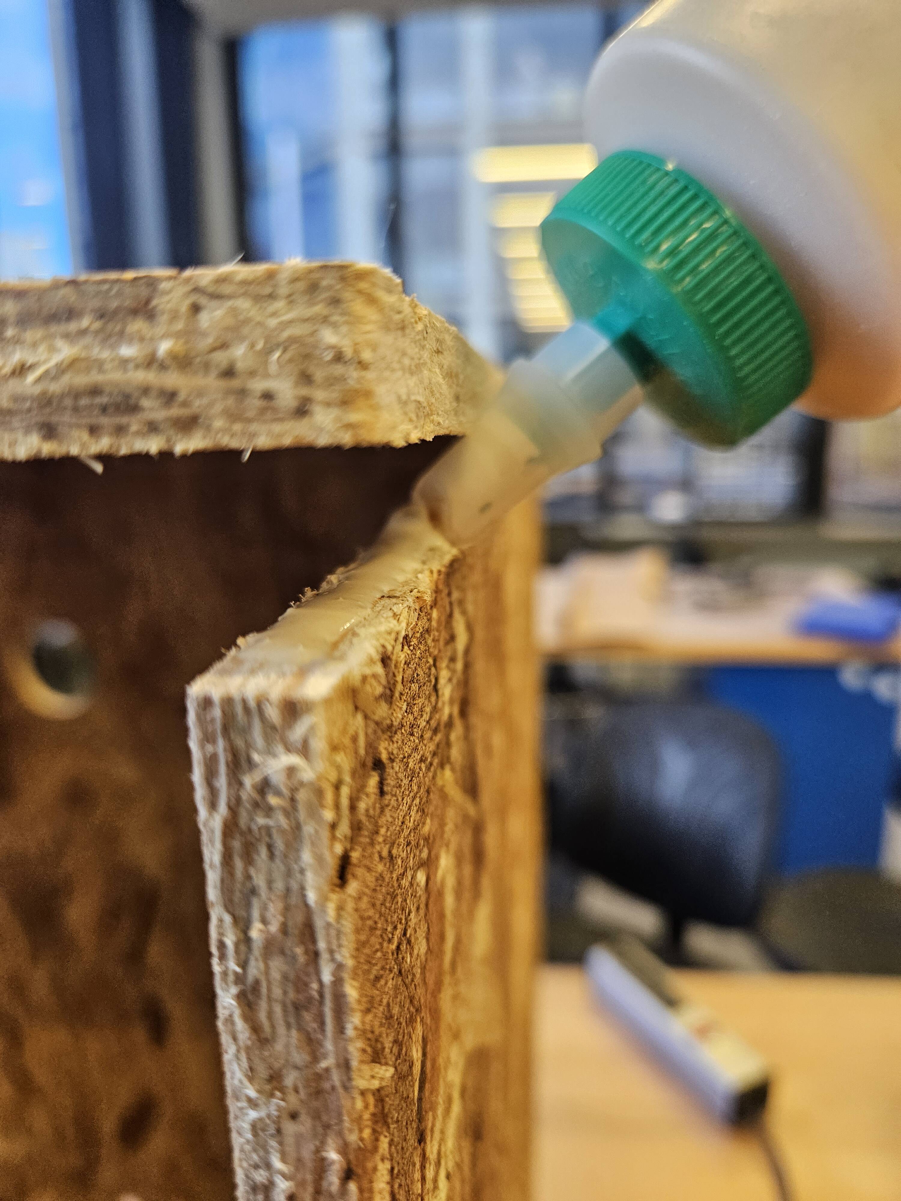
- Wood Glue (Titebond III)
1) CAD our Design
First lets take a paper design. We make this via OneNote the translate that over to rough mapping on our OSB.

Design Dimensions We needed to fit on one 4x8 sheet (or subsections thereof ) in order to fit on the CAD machine. We had a good idea of how big the panels needed to be. So we layed them in a flat orientation so that we could best plan out our space.

We can then adjust some of the dimensions to design around our stock. Our stock will be 2x boards of 48" x 48". We will add a full inch buffer (1/2in alll the way around). This will help us account for both machine dimension limitations, cutting widths of the tool, while giving me a little breathing room. Ultimately the box will be 27in x 20in x 20in.
We then plan the large files roughly on 48in x 48in OSB sheet. This is a rough layout and gives a sense of where we can place parts. This will be useful for our CAD > CAM transition.
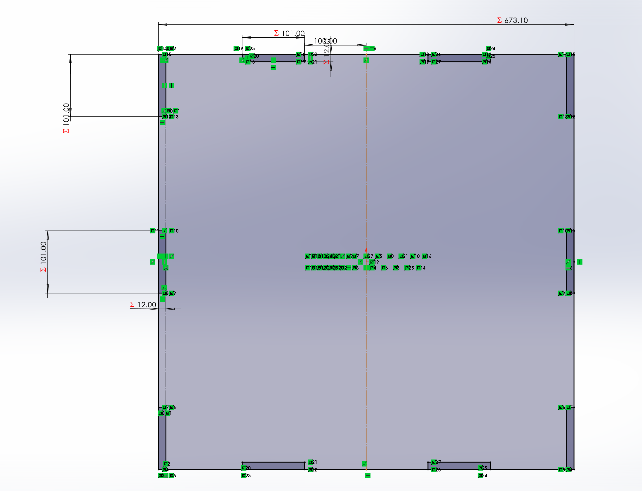
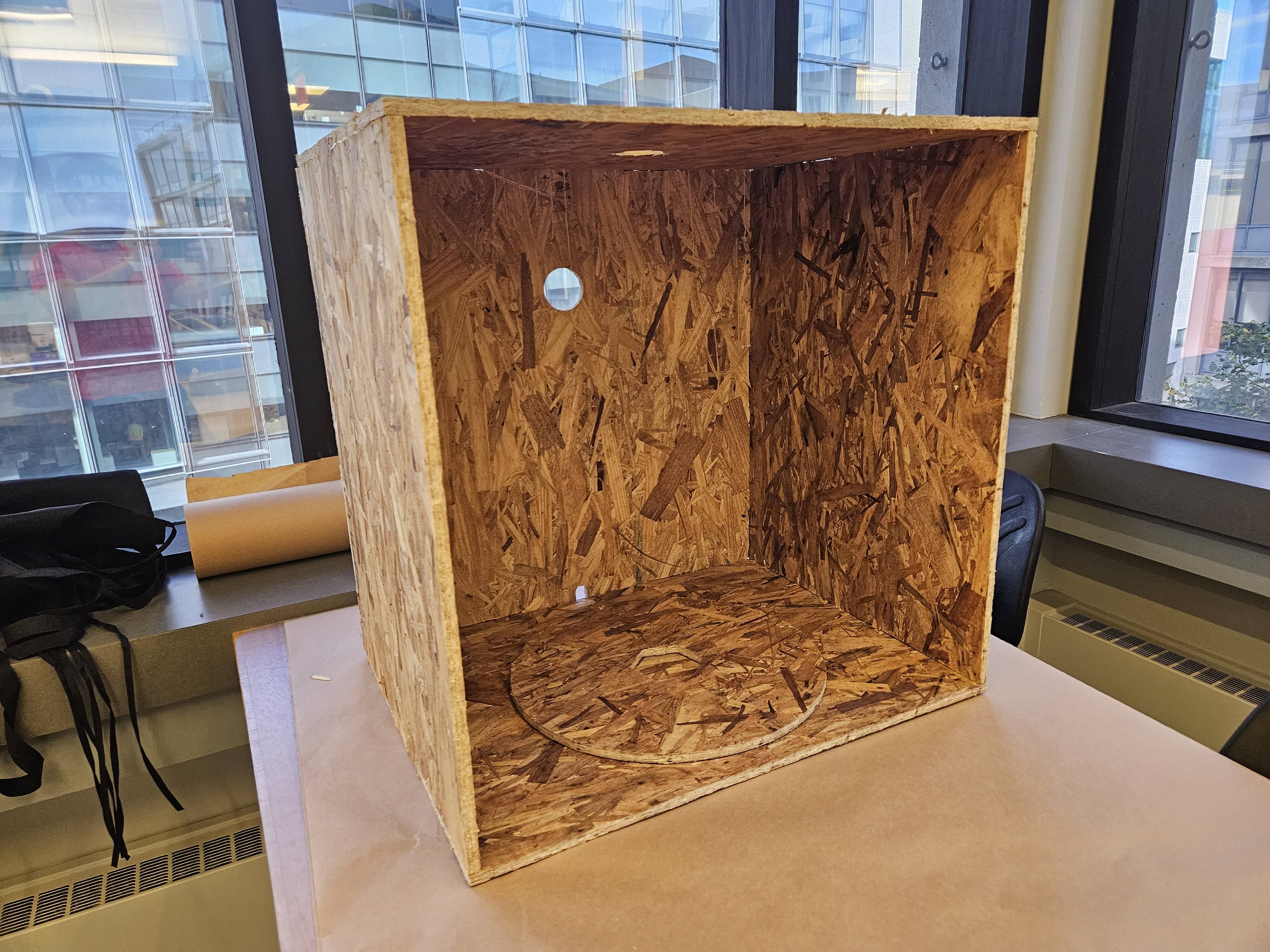
We first CAD'ed our design. Using our box, our OSB is 7/16in thick. We created this design parametrically. For most of the joints, we will butt joints since we are limited to a 3-axis machine. The actual machining is actually extremely simple - two holes (one for the vent on top, one for the rotating bed), two light fixtures at the top, then routing on the bottom top.
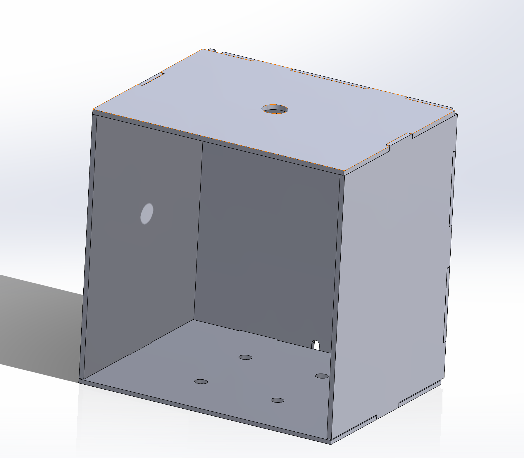
This is how our box looks in design
We took our design, exported into Fusion360 then pushed it into our models. Due to the convenience factor of our design, we were able to cut it out in 2x 2ft x 4ft sheets and 1x 4ft x 4ft sheet.
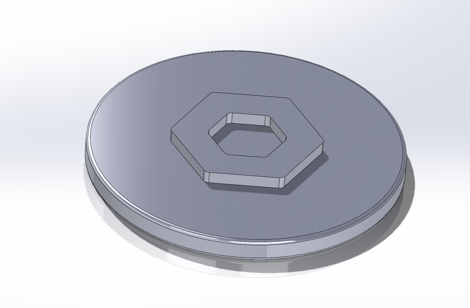
Additionally, we CAD'ed up an adapter plate for our Lazy Susan. The intent is to 3D Print this at a later date.
Cutting
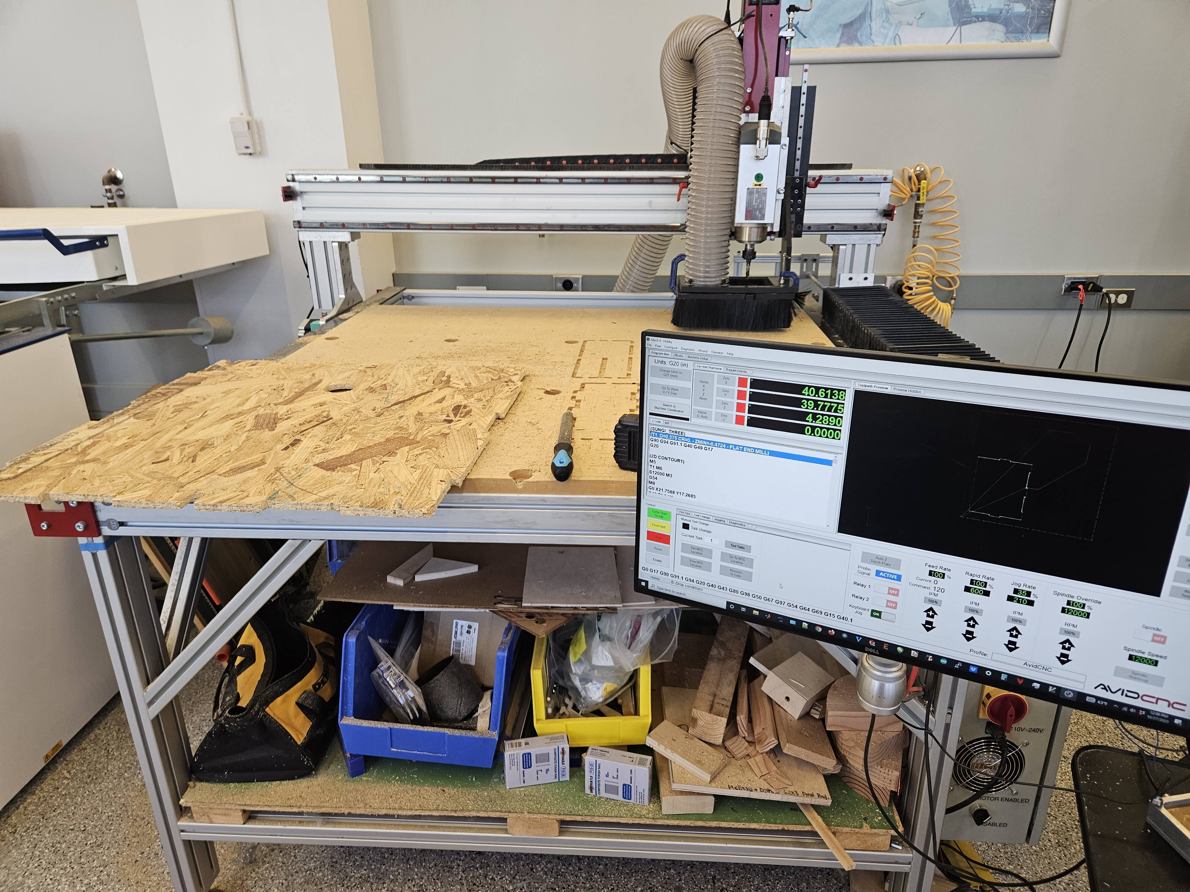
Here we put the OSB on the wood mill. We translated our CAD model into CAM using Fusion's native adapter.
Lessons Learned
- OSB is a pain to work with (this was previously learned, but reinforced today)
- Neil is wrong - OSB furniture doesnt look that great. Sorry #truth
- Make something big week also means move something big week.
- © Untitled
- Design: HTML5 UP