This was
The Fourth Project
---Magnets---
3D Printing! (AM)

Aesthetically, we can create the most out of this. We're going with the EGG theme - so we sliced an egg and looked at creating a screen/buttons for it Hopefully this works out. Thank god for 3D printing - complexity is free

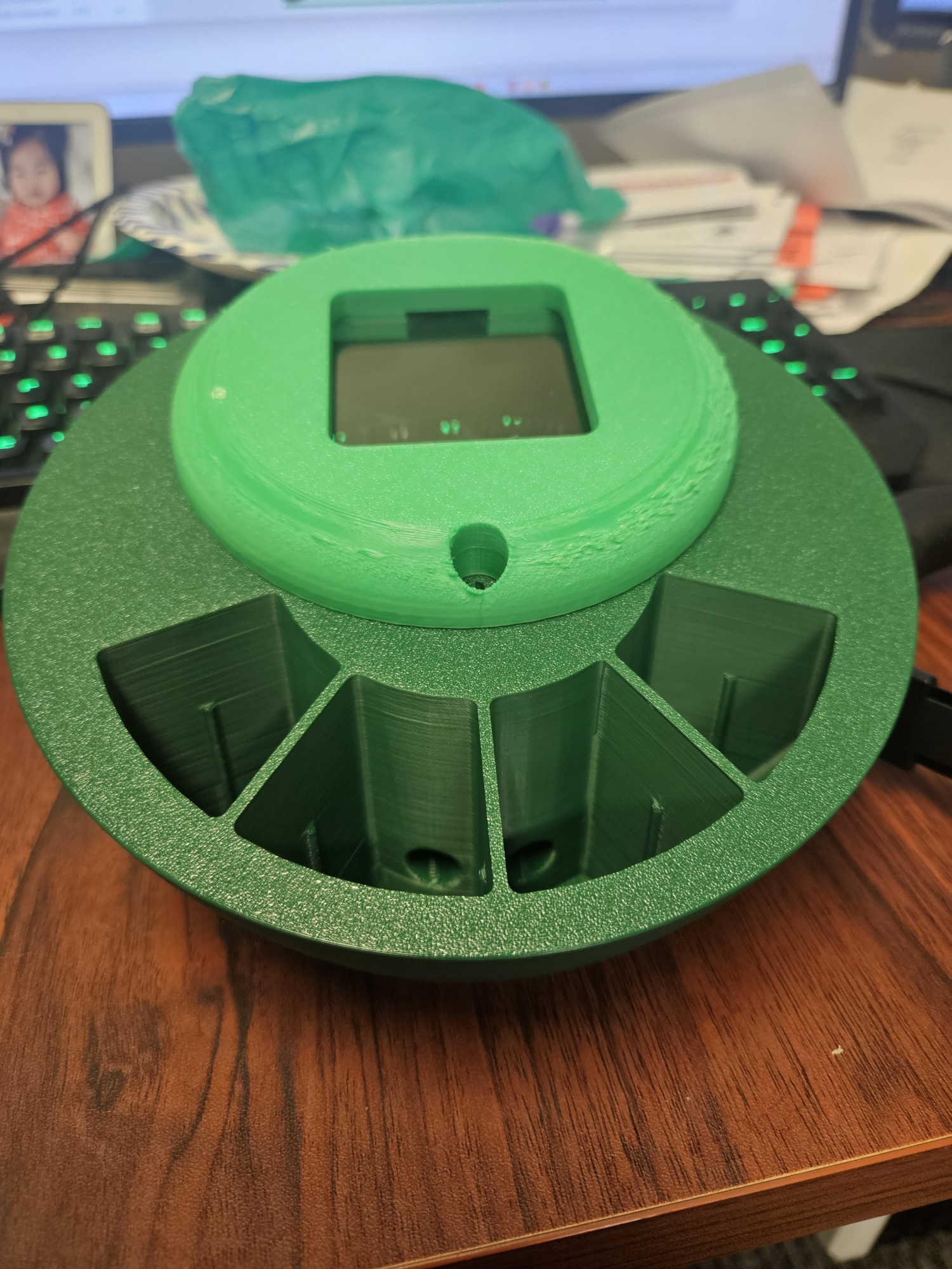
Inner Workings
This is before we start planning our wiring diagrams!
Note, our wire-ways have to be tubular - this will prevent droopy overhangs.
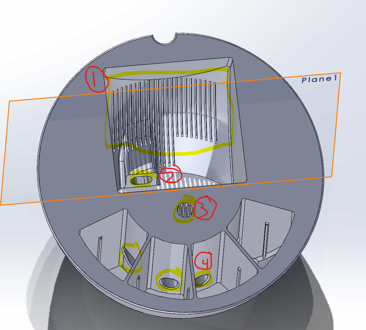
Time to create the actual inner workings
List:
- Speaker placement + guard
- Button wiring channels
- Supports for board placement
- Microphone placement
- Light sensor (to change ambient light) - unsure on dimensions but we will leave room at the top for this.
- Magnetic insert Placement
This will let fulfill the course requirement of building something that cannot be "subtractive manufactured"
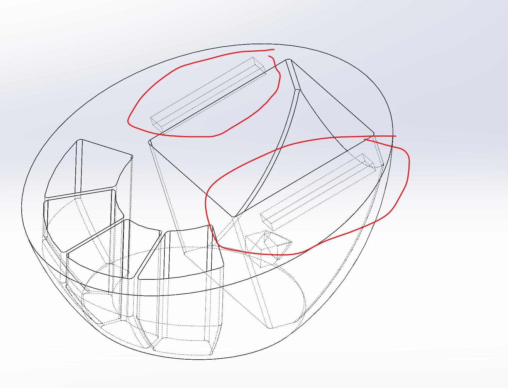
Magnets
Modeling the magnet portions. We can see when we go into the skeletized view that it works
We were able to successfully control the lights
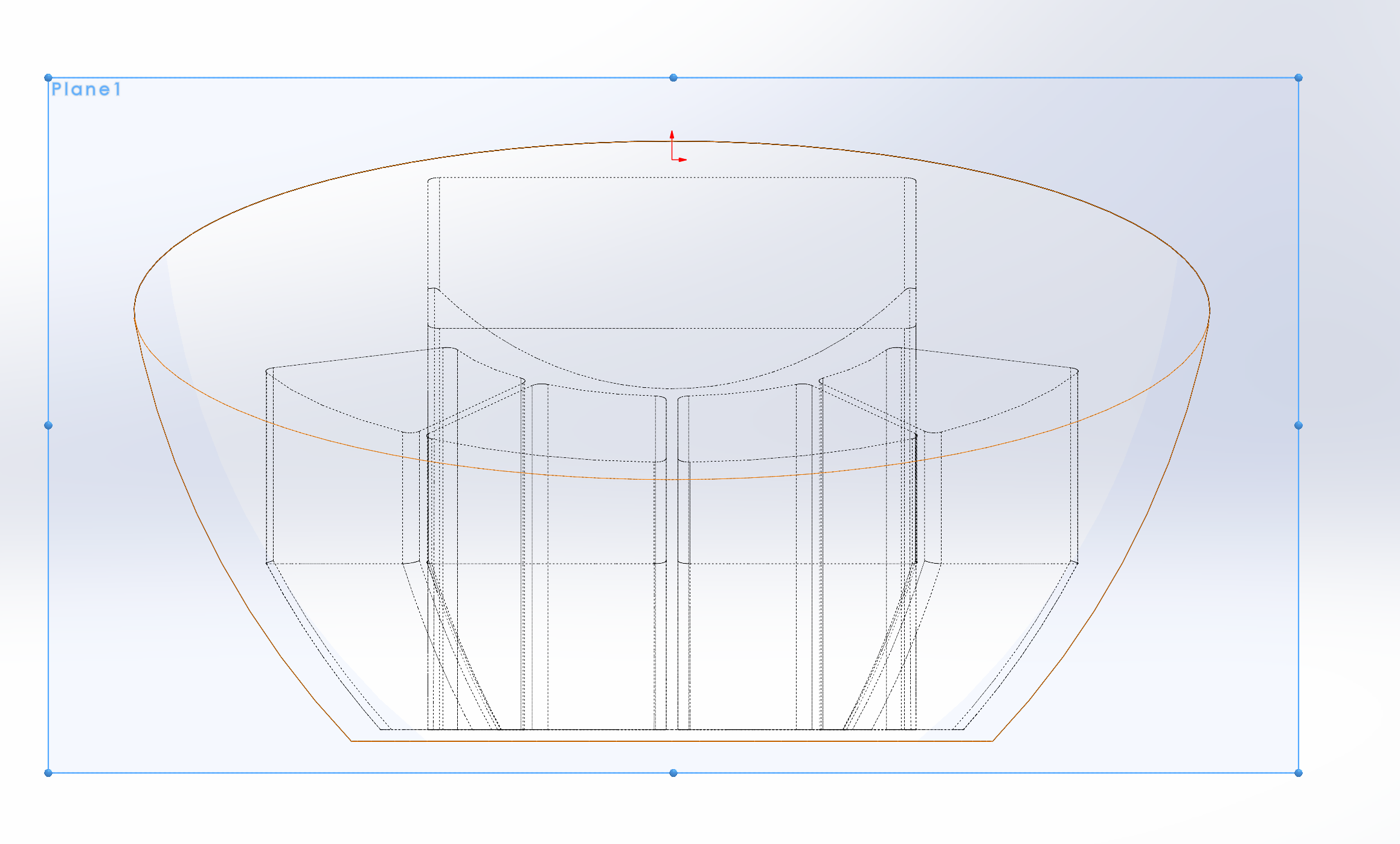
Geometry References
Note - we take a look at this geometry now - we will need this down the line! In order to create our next face! We also need the 188mm dimension as well. This will allow us the cutoff between the first and second circles.
Because we sliced the face of the egg at an angle, it is not a perfect circle. This means that our lid will not be a perfect circle as well!

Button Geometries
>Before creating the buttons, we know we want the buttons to be pushed up and down, so we will design alignment "rails". This can be created before we even get to the cutout piece! Lets, hope this doesn’t screw up features down the line.
These buttons are going to be so annoying to model…. I can see it now…...l
Modeling Supports
Fillets to prevent some serious droopy overhang We can tell this is not going to be enough because the build surface (the "top") shows that even with the filet, there will be floating pieces. We will have to manually add supports!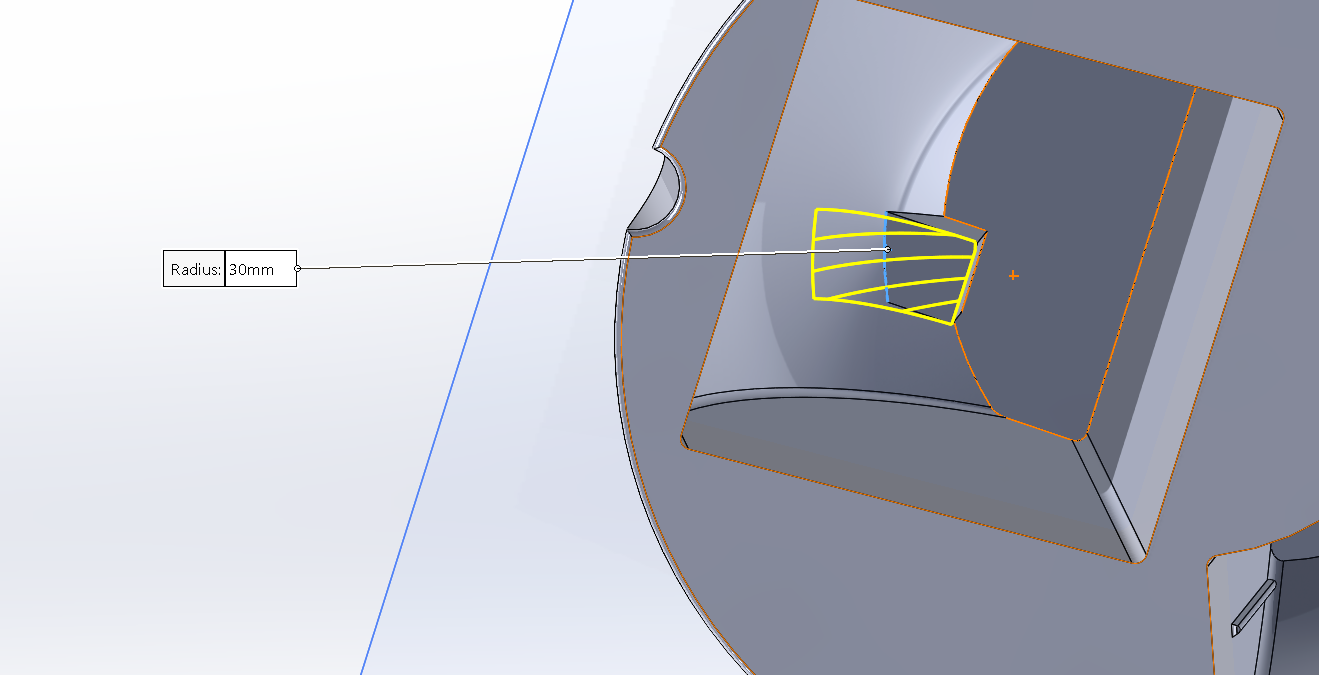
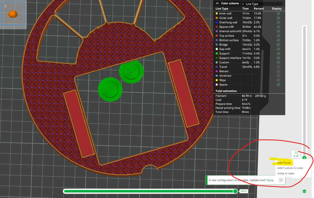
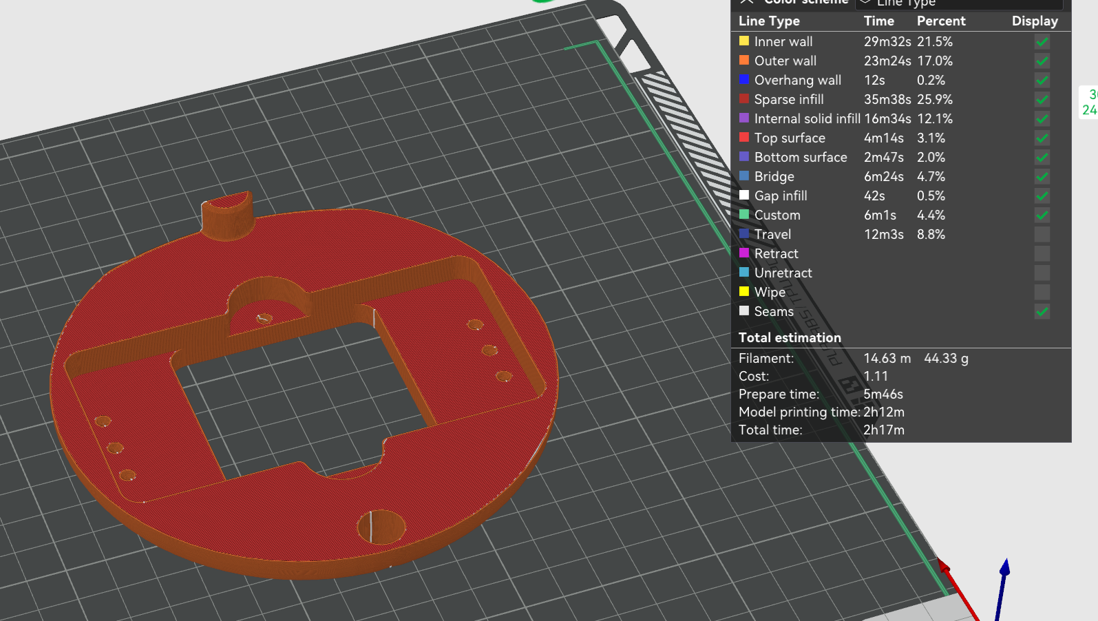
This is where I "Painted" my supports Then I used the below image to show how I inserted the magnets. We added a pause at layer 52. This is the last layer before the slicer will add material over the magnet cavity. G Code M400 U1.
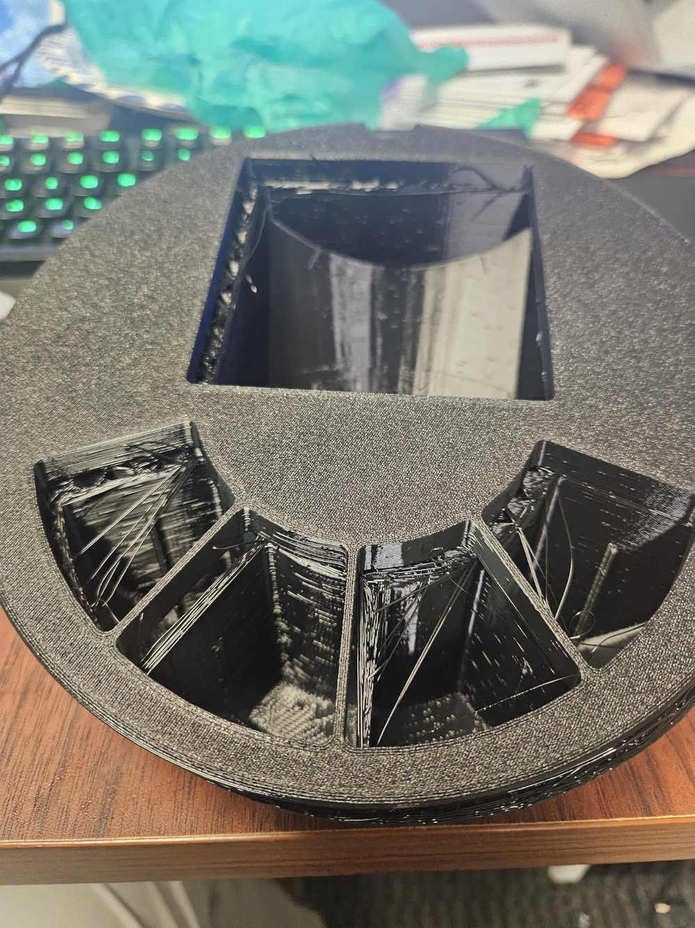
Printing Issues
Once I began printing, I waitied until the pause at layer 52 in order to insert the magnets.
 After attempts at printing, I realized i ran into issues. I had not given the magnets enough clearance. I added another mm to the thickness of the printer. Than I repeated the same process (not captured). This allowed me to get the magnets printed over without any issues!
Afterwards, I added a few more features
- Speaker Grill
- Hole for USB-C cable
- Hole + mount locations for microphone
- Tunnels for button cabling
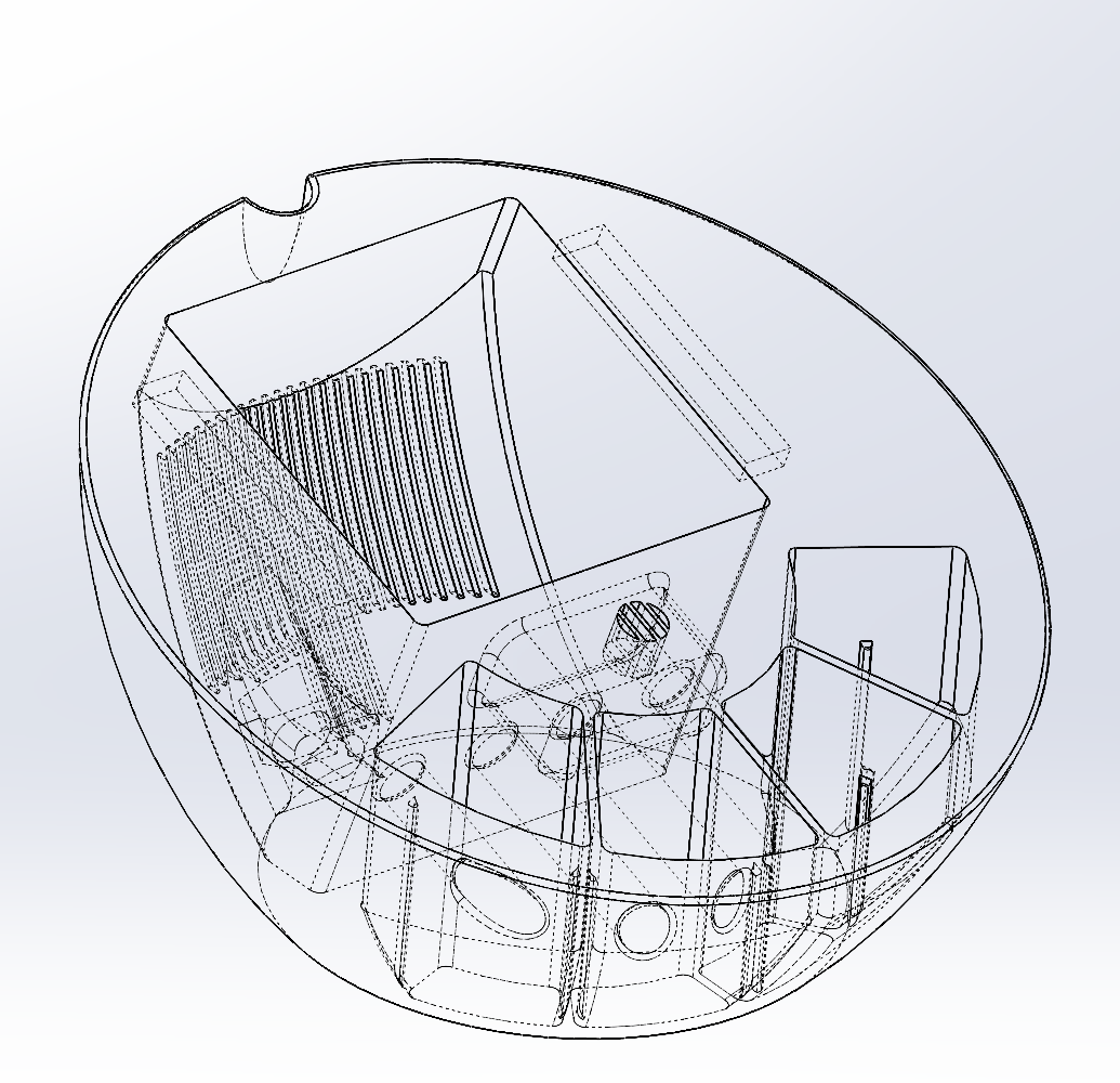
The same thing but skeletized in order to see the internal structure
Revision To Do List
- Final Board dimension + Placement
- Adjusted wire dimension passthroughs li>Speaker mounting points + Bracket + methodology
- Microphone mounting point + bracket (this will probably be a slide in bracket so I will need mounting screws on the backend, towards the buttons)
Lid Design
We focused on using 7 holes. This will allow the steel bolts to interact with the magnets on the base. The 7th screw is just to make sure the screen holds in place.

We added a notch at the top. This is an alignment tool that will hold the lid up! Additionally, we added another notch to the screen. This will allow us to add more alignment to the acrylic screen + add more mounting points when we get the circuit board on
Reprinted with a notch (for better alignment and less falling off)
FINAL PRINT
- © Untitled
- Design: HTML5 UP