This was
The Ninth Project
Input Devices
Solder, Test, Resolder, Retest

Summary:
Today, we will be using our previously made circuit board in order to build out an input device. We used an ambient light sensor (phototransistor) this week in order to generate "levels" of light. This will allow us to control the output of the screen for our final project
Tools
Software- VSCode (had errors pushing to PicoW)
- Thonny
- Soldering Iron
- 4x LED
- 4x Resistors (330Ohms)
- Phototransistor: PT15-21C/TR8
- Wires + Solder + Testing Board
Assigment Note:
*I believe my 2yo daughter played around with my board.... near our trashcanWARNING WARNING WARNING
If your name begins with N- and ends in -EIL GERSHENFELD, do not continue below:
.... There are breadboards.....
I like breadboards...Please dont fail me.
WARNING WARNING WARNING
Design - PhotoTransitor
First, lets take a look back at our board - Pico W (RP2040). In order for us to use our transistor, we need to leverage our ADC pins (GP 31/32).
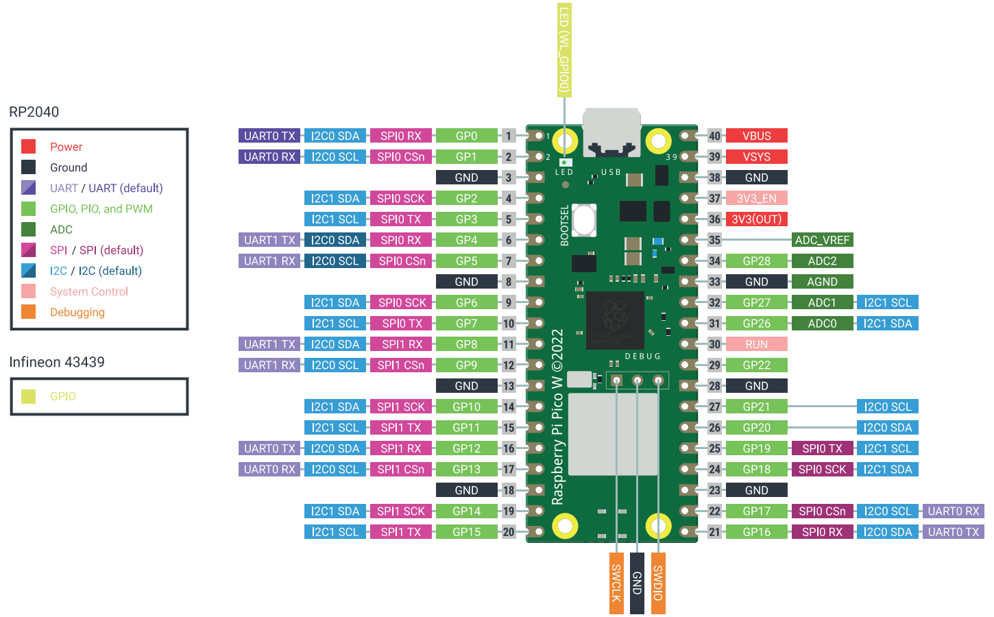
I assume that for 3.3V the ADC digital conversion is based on 1024. This means that value of 1023 will be highest (at 3.3V) and 0 would be the lowest (at 0V). We tested this assumption when we build our boards.
Design - Building the Code
Due to the some scheduling conflict - we will build our code before our board.
def TransformReadings (SensorReading):
   SensorBot = 200
   SensorTop = 1200
   LightAdjustment = .9
   SensorRange= SensorTop - SensorBot
   SensorReading = SensorReading *(-LightAdjustment) + SensorTop - SensorBot
   SensorReadingPercent = SensorReading/SensorRange
   SetPWM = int(65535 * SensorReadingPercent )
   SetPWM =   65535 - SetPWM
   print(SensorReadingPercent)
   return SensorReadingPercent
We then pushed this code to our board and soldered on our PhotoTransistor
Testing this via my flashlight on my phone Range from ~-4600 when the flashlight is on. Then it goes down to -3800 numerically when the button is not pressed. The below is a screen shot of the value of the LED in normal room lit conditions. We expect this to be normal for most people. Unfortunatley, this will most likely not the be the photo transistor that will not be utilizing as it doesnt have the fidelity we want. We will either need to use a resistor to help control the fidelity of the transitor or we will need to get a new phototransistor all together.


Design - LED
Since we know what our lower and upper bounds are, we can translate this into an percentile output.
Note - I want to do this automatically; Im not sure how to do that process wise.
We can then adjust our top and bottom values in order to get percentile rather than an absolute value.
This will allow us to utilize this screen for the future.
Additionally, we pushed this into four different tiers.
Since our bottom values ~3800-4200 seem to be the most common in normal lighting conditions, we will leave the bottom heavy.
We will create step functions not allowing lights to only go one step up or down, rather than jump immediately high and low, similar to the bouncing effect.
Final Result
Final Used Code
Note: Some of the values below may not be referenced as they were built on earlier code. The below code is only the relevant snippets for this week
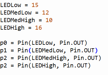
#Pin Numbers are in GPnumbers
LEDLow = 15
LEDMedLow = 13
LEDMedHigh = 12
LEDHigh = 16

p0 = Pin(LEDLow, Pin.OUT)
p1 = Pin(LEDMedLow, Pin.OUT)
p2 = Pin(LEDMedHigh, Pin.OUT)
p3 = Pin(LEDHigh, Pin.OUT)
p0.off()
p1.off()
p2.off()
p3.off()

QuartileLow = .25
QuartileMedLow = .5
QuartileMedHigh = .75
QuartileHigh = 1

def TransformReadings (SensorReading):
	SensorBot = 200
	SensorTop = 1200
	LightAdjustment = .9
	SensorRange= SensorTop - SensorBot
	SensorReading = SensorReading *(-LightAdjustment) + SensorTop - SensorBot
	SensorReadingPercent = SensorReading/SensorRange
	SetPWM = int(65535 * SensorReadingPercent )
	SetPWM =   65535 - SetPWM
	print(SensorReadingPercent)
	return SensorReadingPercent

def QuartileLEDON (Quartile):
	if Quartile <= QuartileLow:
		p0.on()
	if Quartile <= QuartileMedLow and Quartile >QuartileLow:
		p1.on()
	if Quartile <= QuartileMedHigh and Quartile > QuartileMedLow:
		p2.on()
	if Quartile > QuartileMedHigh:
		p3.on()

def AllLEDoff ():
	p0.off()
	p1.off()
	p2.off()
	p3.off()

while True:

	logic_state = buttonpress.value()
	led.value(0)             # led will turn OFF
	count +=1
	print ("button is not pressed")
	led.on()
	time.sleep_ms(1)
	led.off()
	#blinkfast()
	BrightLevel = PhotoResistor.read_u16()
	LEDPWM = TransformReadings(BrightLevel)
	QuartileLEDON(LEDPWM)
	time.sleep(.25)
	AllLEDoff()
- © Untitled
- Design: HTML5 UP