This was
The Sixth Project
Electronic Production
PCB making

Summary:
- Rebuilt our circuit to design for the manufacturing constraints
- Redesigned our ambient light sensor (realized that it wouldn’t be able to detect light
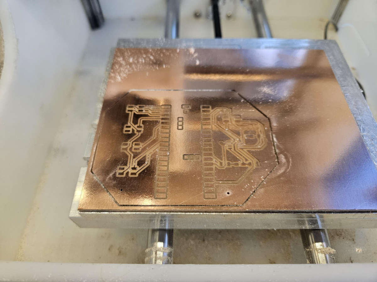
- Manufactured our board
- Soldered on our components
- Tested power and components through buttons and lights
Tools
Software- Fusion 360 / EAGLE
- Bantam Tools (CNC)
- The Other Mill by the Other Machine CO (Bantam Tools)
- Soldering Iron
PCB ReDesign
After discussing with Anthony on the best way to build a better circuit, we learned a few things. Firstly, we found that we could adjust the rotation of the circuits because they're bidirectional or not direction dependent. Additionally, we learned between schematic and design that it was important to iterate. This alleviated a lot of the software constraints tying ground nodes
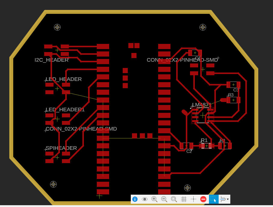
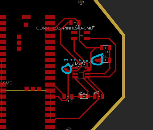
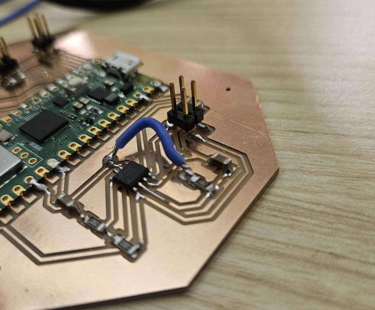
One of the key design reworks was minimizing the double sided PCB and utilizing a jumper. We made a little "landing pad" by creating a 50mil wire extension. This will help us solder our jumper. We did this instead of our 0 ohm resistor. Even if we moved our resisitor / capacitor, we would still have to jump two lines.
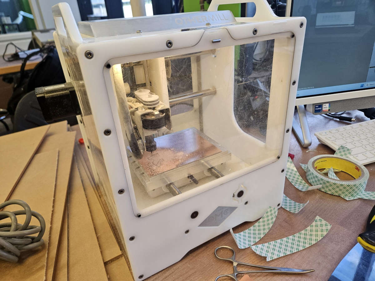
Building our CNC
We then got on the Bantam CNC and cut out our board. This board was sliiiiick. It had a brand new drill bit and no fraying or post processing required.
Referencing our earlier diagram from LM4871, we know that R1, R2, and R3 are valued at 20 ohms and that C1, C2, and C3 are 1 microF. We realize that the amount of resistance really became inconsequential with our testing.
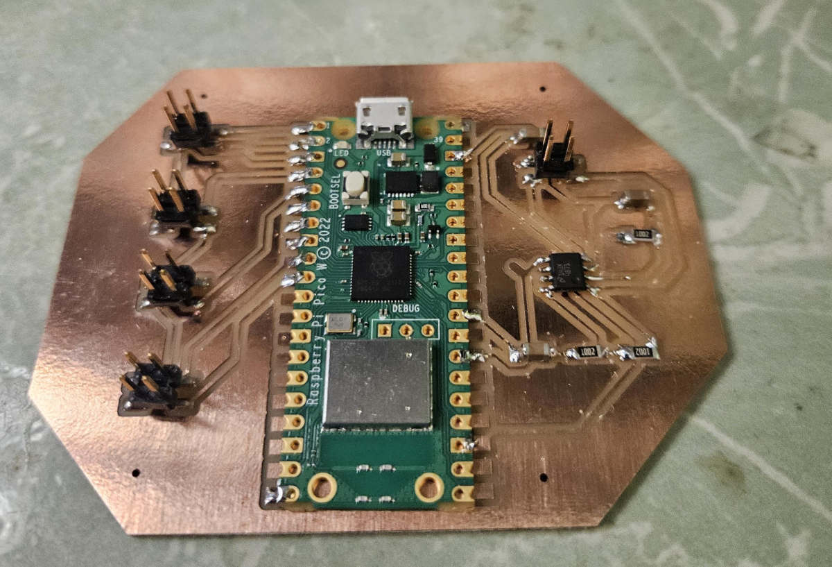
Going back to our original PCB design, we now have to manually place the jumper cable. Physically this becaem more annoying than originally anticipated
Lessons Learned
- Firstly, when you design the schematic with respective resistances and capacitances, check the type of resisotrs you have i.e. I needed to have 2x 10ohm resistors as we dont have a 20Ohm resistor
- Secondly, jumper cables are a great way to push circuits over other circuits.... BUT THEY ARE EXTREMELY FLEXIBLE
- Thirdly, the "50mm" pad was a success! It worked great except for the flexibility of the above
- Finally, the mounting holes were too small. This was the maximum option on EAGLE but the input was later found out to be nondescrete.... whoops.
- © Untitled
- Design: HTML5 UP