Solar powered, autonomous boat + payload (e.g. drone, environmental sensors, small submarine) system
REVISED IDEA:
Radio controlled Electric Boat.
It became clear quickly how difficult the former would be in the time we had, so I downscaled to an RC electric boat for now, with the goal of upscaling over IAP to the original plan! I am keen on the original idea due to its environmental relevance and potential applications. Having said that, I am happy to start with a smaller scale project, and then expand upon during IAP to my original aspirations.
Solar powered boats aren't new. See saildrone. Having said that, they haven't been deployed in rivers for environmental sensing, nor do they carry payloads like drones or AUVs.
In this project I designed and manufactured every single part including the hull, except for two boxes I used to house components + basic electrical components. Processes included 3D Printing, laser cutting, CNC milling, composite manufacturing, PCB design/milling, embedded programming.
The list of components I used included:
NRF24L01 module * 2 = $10
Raspberry Pico W * 2 = $10
OSB 4*4 sheet = $1
4 sq ft of acrylic = $10
3D Printed PLA = $1
2 * Copper Boards + Jumper Wires = $<1
2 * black plastic box < $1
LED < $1
1 * lithium ion battery = $10
I estimate the total cost of thise boat to be around $50 in terms of manufacturing. All of these components except for the mesh and lithium batteries were taken from the lab.
There are 5 major parts of the project. I explain each of them here, and then discuss how they were integrated with one another. Some of these were covered in past weeks, in which case I will adequately reference these weeks and add any additional comments.
We shall finish off with integration, and a demonstration of the boat functionality.
1) Hull
The hull of the boat is made of high density insulation foam (high density is relative to other foams, and it only has 0.05 g / cm3 density). It is coated in Fiberglass.
For a full explanation of everything, I would encourage readers to visit Week 13: Wilcard Week, where I went in depth on how to build these hulls.
2) Boat Deck
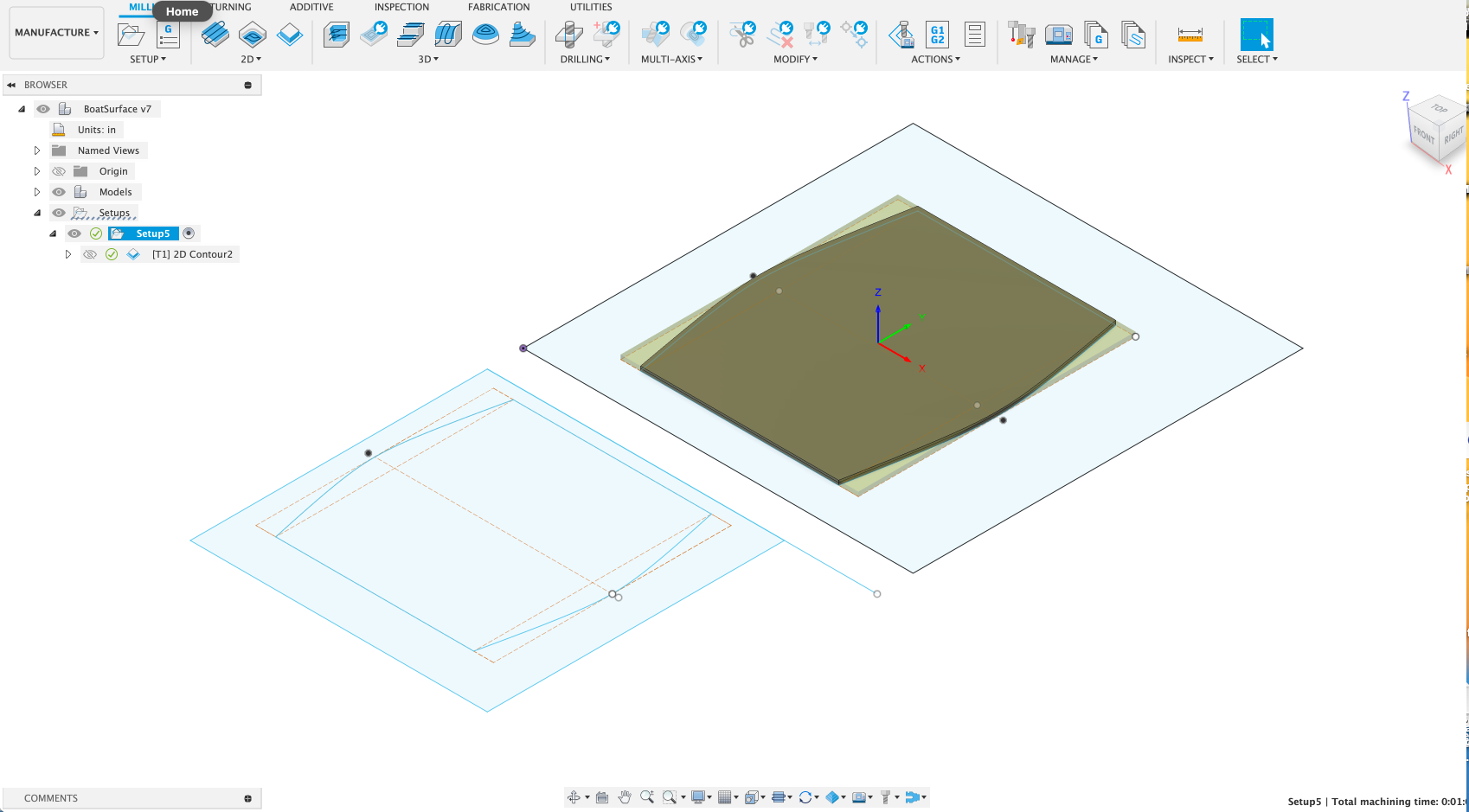
I decided to make the boat deck out of OSB. It is reasonable lightweight, strong structurally, and can be milled/manufactured in large sizes. The maximum available size of acrylic was 12*24 inches, and I needed about 24*28 inches for my size of hull.
To this end I measured out the correct sizes and designed the hull with conic curves to match the hull in fusion.
I then attached the surface to the hulls with epoxy resin, adding on hot glue to suplement as there wasn't enough epoxy.
3) Electronics
The electronics in this project consist of a transmitter circuit and a receiver circuit. The circuits with demonstration are shown/discussed/explained in Week 10. The final product includes the PCB's shown, and will be demonstrated at the end of this.
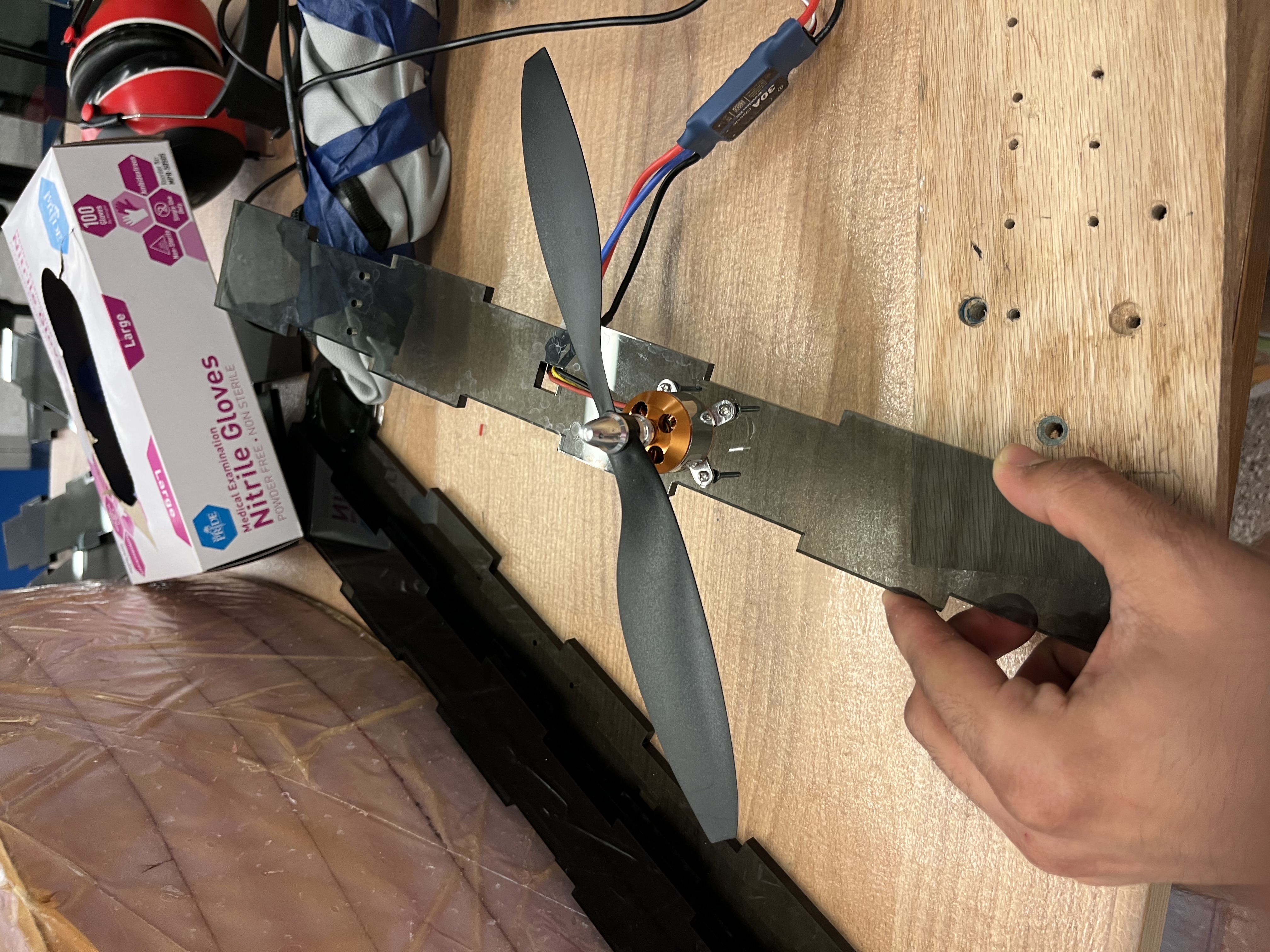
4) Fan Stands
The fans will need to be attached to a stand. I have decided to make this stand about 45 centimers tall, account for the diameter of the fan itself (about 32 centimers).
The stands are made of acrylic, consisting of 4 pieces with holes for bolting the motor + casing.
The acrylic will be assembled with the motor casing. For now, I've included a photo of a motor attached to the frontal panel.
5) Motor Casing
Having propellers without casing/grills led to incredible airflow/propulsion. However, the blades were unsafe in a classroom setting.
Therefore, I was encouraged to built a casing of sorts with grills to prevent any accidental human contact while the boat was operational.
To this end I CADded a round case of 30 centimeter diameter (propellers have 25 centimeter diameter). DUe to the size of them (31 centimeres in diameter), I split it up into four pieces and attached them with hot glue. Techniques like making dowels in the plastic weren't effective as the dowels were too thin.
After these were attached together, I connected the fan ring to the stand just as the motor was connected, via bolts. Then I addded mesh, using zipties to secure their position.
The product looks like the following from the back:
INTEGRATION + FINAL ASSEMBLY:
The next steps included 1. Gluing the pieces of acrylic together with hot glue to form a rectangle, 2. Attaching it to the base, and 3. Placing the electronics.
Step 1 was fairly simple. Step 2 involved adding a small block of wood in the center of the rectangle, and epoxy-ing the whole bottom to the boat. Step 3 involved putting the transmitter's PCB into a box, and the receiver's PCB into a box. For this purpose, due to time constraints, I simply adapted an available plastic box rather than reprint/cut one from scratch, especially since I did make the major components of the boat (hull composites, stands, fans etc.) from scratch.
The boat finally looks like as follows!
Backup video link is here. This video views the boat from all angles + demonstrates all functionality. Please see Week11, which now enables us to use a GUI to control the boat as opposed to a serial monitor terminal.
Backup video link is here. This video shows the boat driving in water. Only one propeller switches on though, as the battery can't really handle high currents and discharges quite quickly. It worked well with batteries in the first video + always works well with a power supply (for example, my demo during final project presentations).
I'm happy the boat worked, even if it didn't move fast! It answers a few questiosn about the feasibility of airboats and how adding grills affects performance. It also confirms my initial suspicions around buoyancy, whereby the boat only sank about 1-2 centimeters into the water out of 20, suggesting foam based hulls are promising choices.
One minute video showing conception, construction, operation, is here.
Backup video link is here. This video shows the boat driving in water. Only one propeller switches on though, as the battery can't really handle high currents and discharges quite quickly. It worked well with batteries in the first video + always works well with a power supply (for example, my demo during final project presentations).

 Download Fan File