This week I focused on programming the NRF24L01 modules. I will be using these modules in my final project, to send commands from my laptop to my boat in order to steer it. I confirmed that this would be a suitable N/C project with Anthony, as it deviates slightly from the traditional goal of bused addresses but still meets the theme of the week.
The NRF24L01 module has 8 pins and operates on radiofrequency. Without a special antenna, it can achieve ranges of about 100 meters. This will be enough for prototyping purposes.
I switched to C/C++, and was able to use the available RF24 library to program my components.
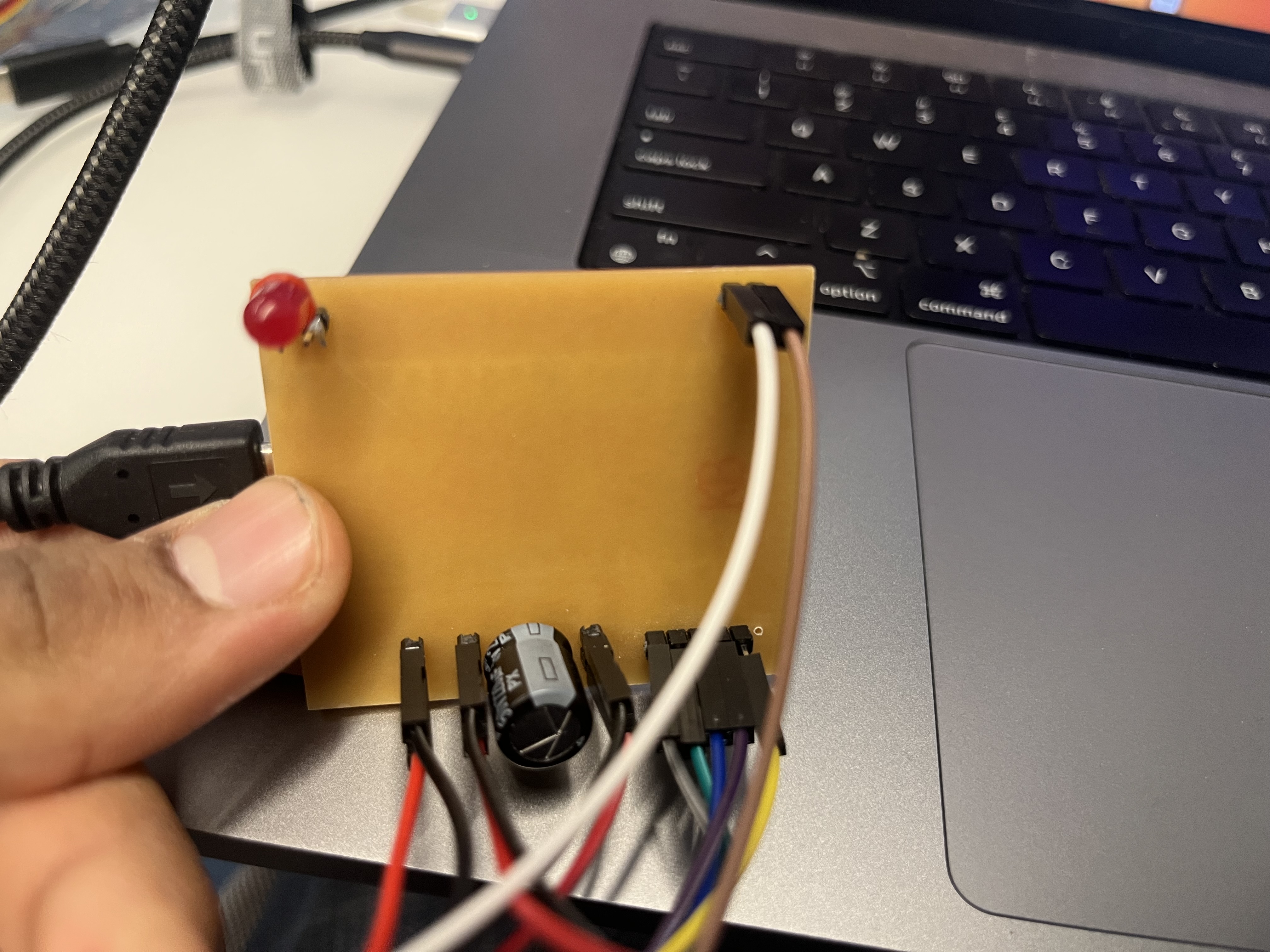
As a proof of concept, I decided to get 2 such boards talking to each other. One board is a transmitter, connected to my laptop over serial USB. Another board is a remote board, containing an LED. The transmitter board turns the LED on.
I got the software done reasonably quickly. The component, however, would be very unstable, recording only about 1 in 50 transmissions.
When connecting additional compoennts to the board, e.g. ESC controllers, this rate would go down even more to virtually zero.
In talking with peers (shoutout Yohan!) + searching online, I learnt that these components are very necessary. I was able to borrow a linear regulator that would take in 5 volts from the pico w and output a
stable 3.3 volts. I also soldered a 100 mF capacitor to the leads of the NRF24L01 as this is a common trick that has worked well for a number of people online. Doing so stabilizes the power supply and almost ensures it doesn't drop below 3.3 volts
The code is shown here. For the purpose of LED Control, the transmitter simply sends a '0' or '1'. The receiver receives it, and switches on the LED.
This can be extended easily to motors, where the transmitter sends a '0', 'u', 'l', 'r', and the receiver then does exactly what was done successfully in output devices week, executing those commands on the motor.
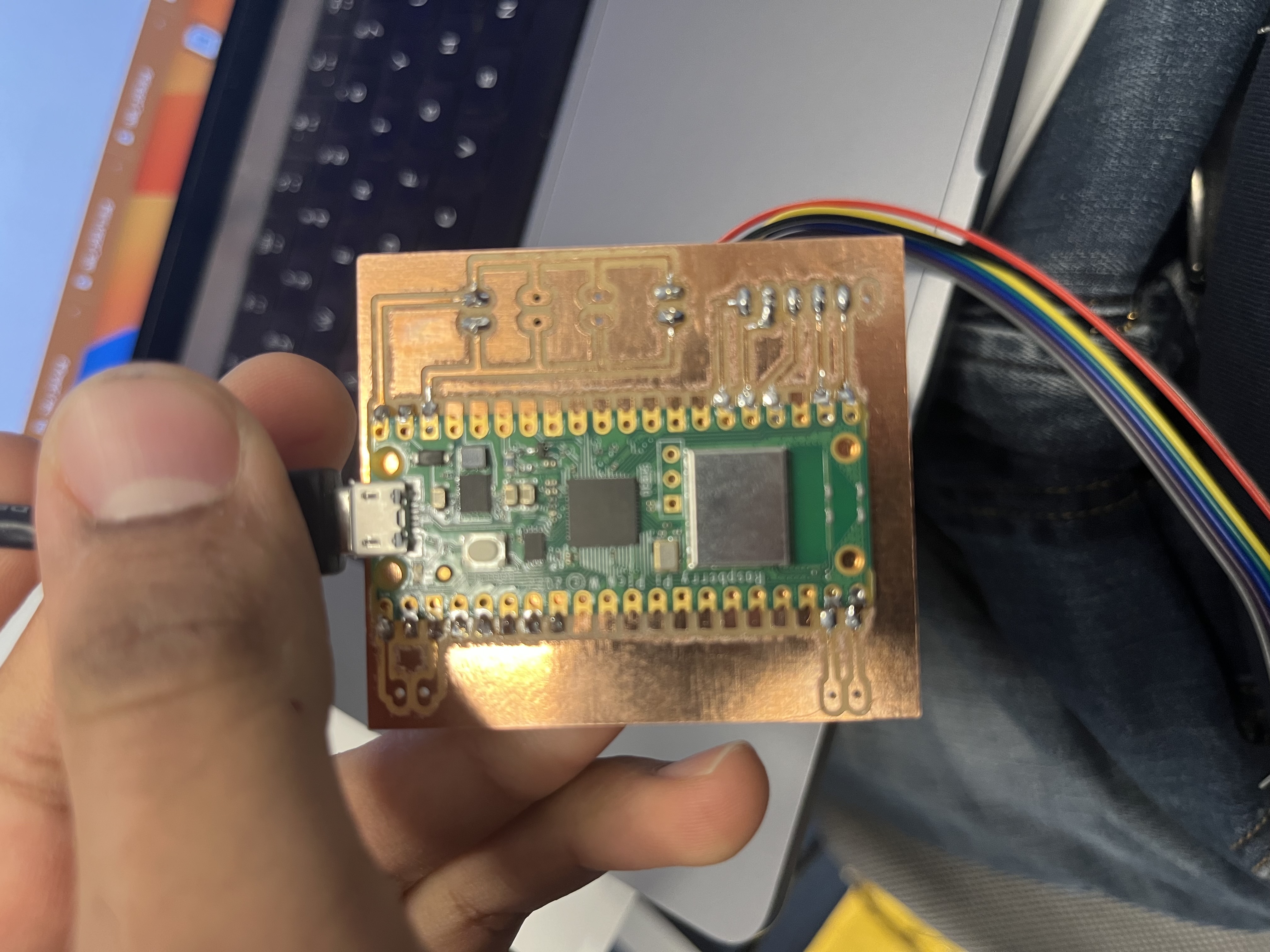
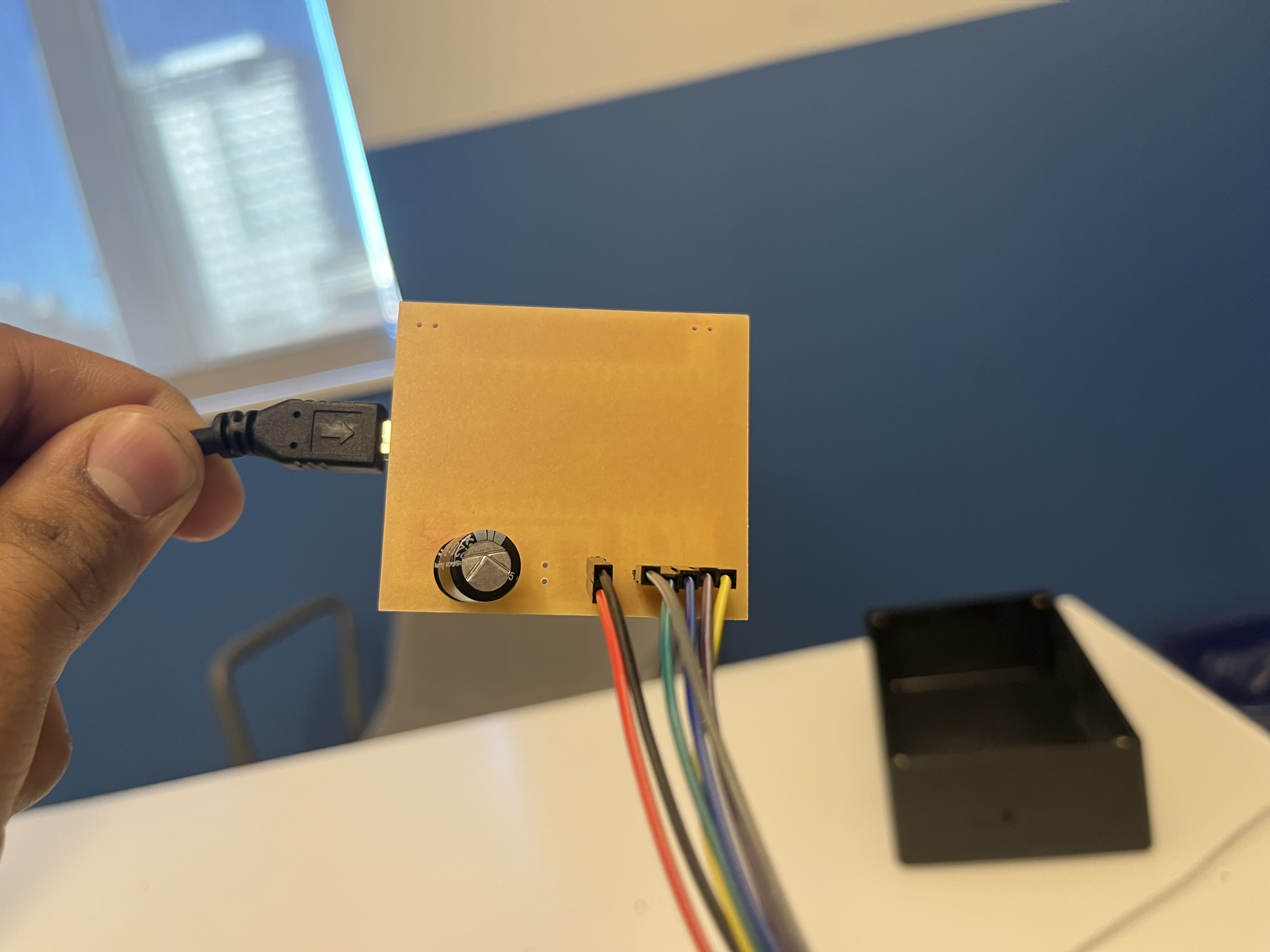
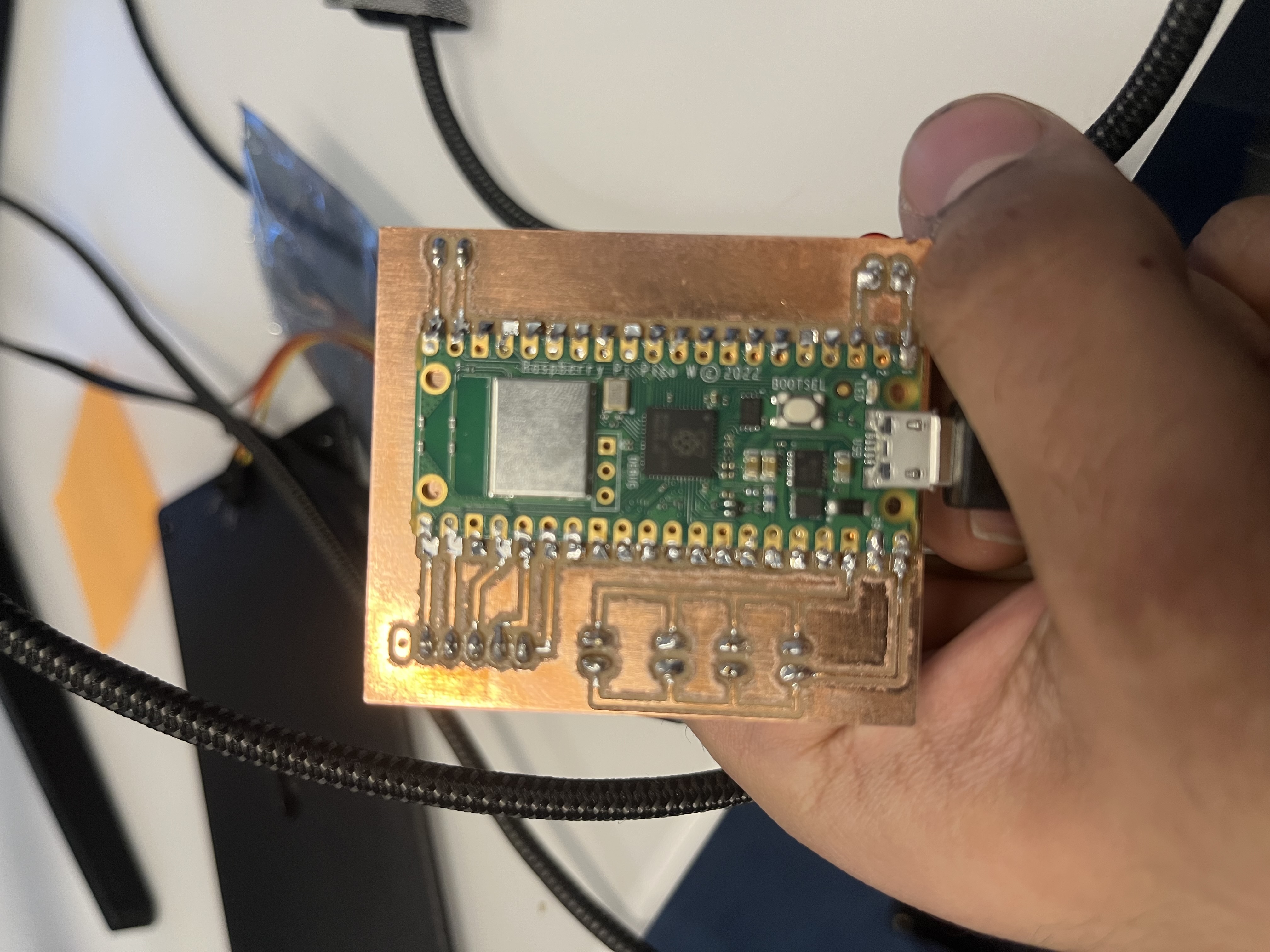
For reference purposes, the PCB boards for the transmitter and receiver are shown here.
TRANSMITTER
RECEIVER
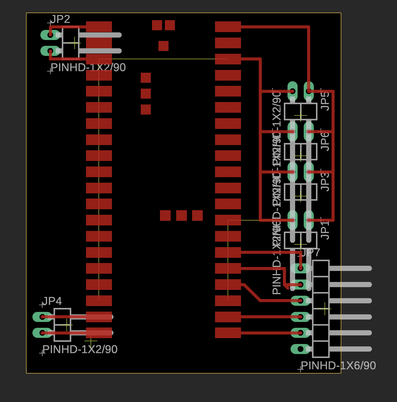
In truth, they are actually the same printed circuit board. The eagle file is shown below. The difference is that the receiver has an LED + 2 packages of ESC connectors connected to itself. Both share the NRF24L01 module and the capacitor.