NOTE: This week includes week 5, where I finished up the GPS code, and also includes additional input sensor output from a Compass sensor.
These were linked to each other, and I got them working at roughly the same time (in week 8), so I included both in this week, and the GPS in week 5.
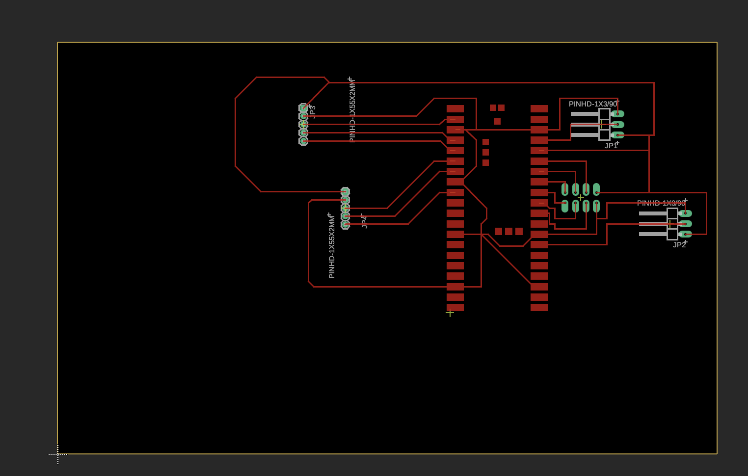
This week I decided to make the PCB I worked on in week 4 and program the GPS module. Future modules will be programmed in future weeks.
I first milled the PCB design.

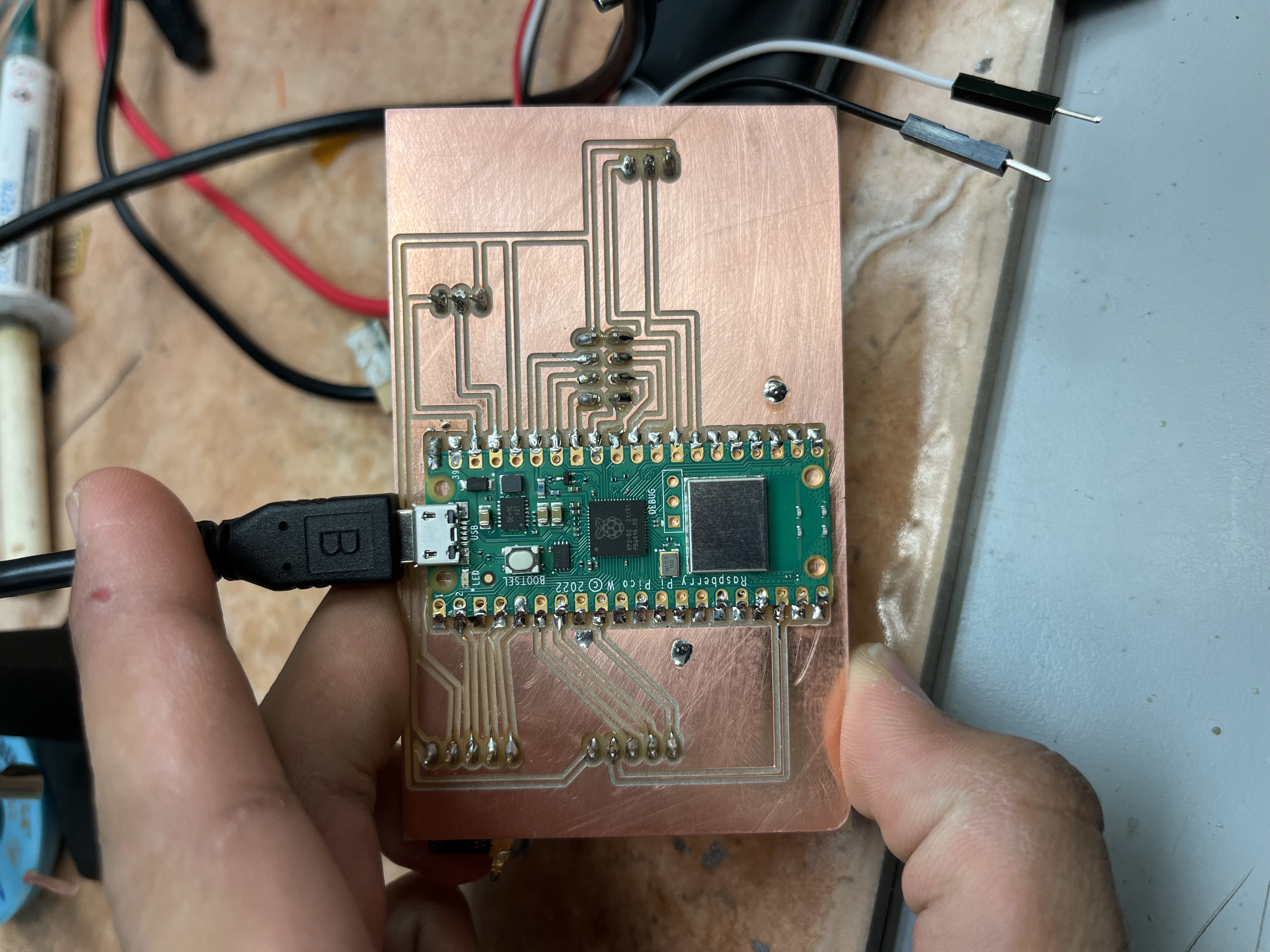
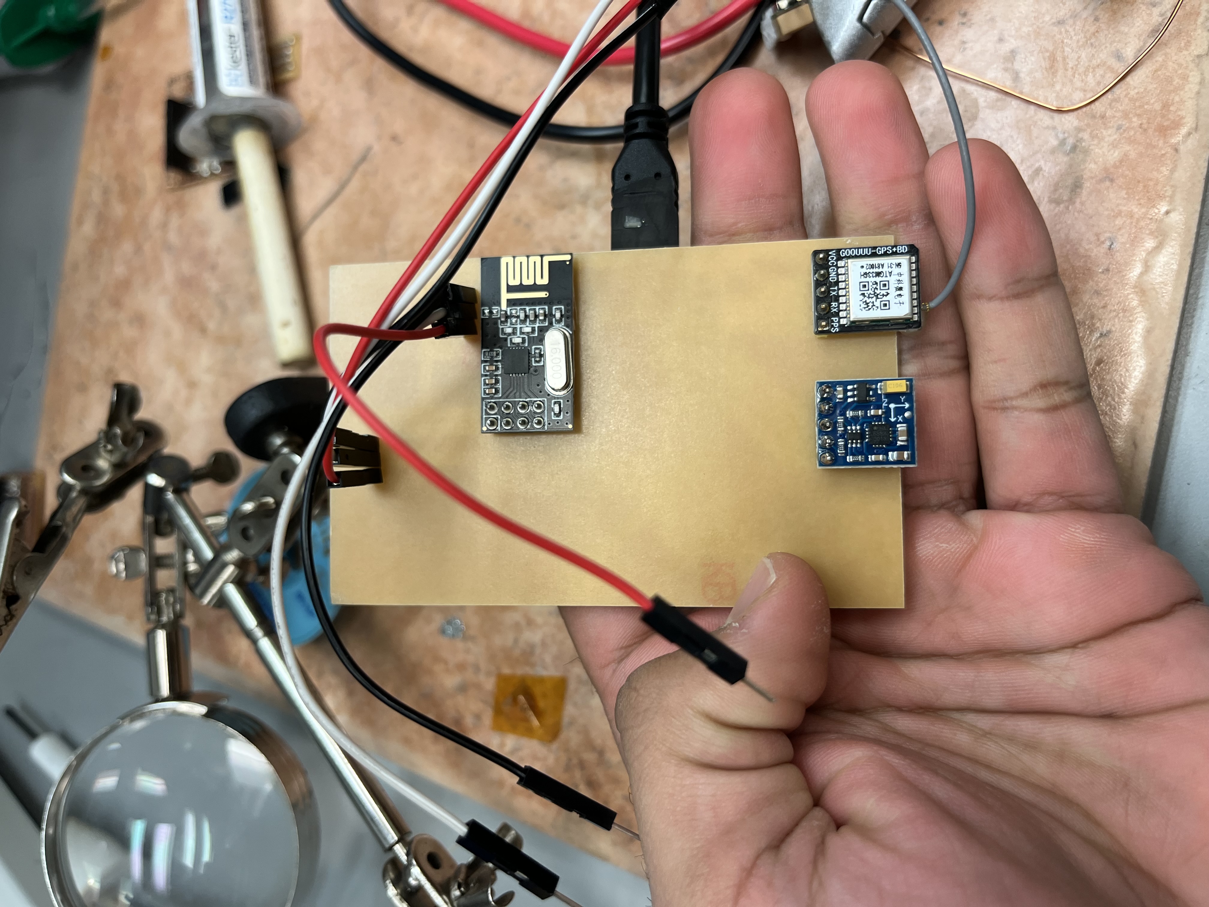
I then proceeded to follow the initial design presented in Week 4 and solder pieces onto the board.
The product. Most components are through hole and therefore soldered from the bottom.
Unfortunately, numerous errors exist in the original PCB. For example, the TX and RX pins of the GPS were connected to the TX and RX pins of the Pico W. I also soldered the GPS into the compass position and vice versa.
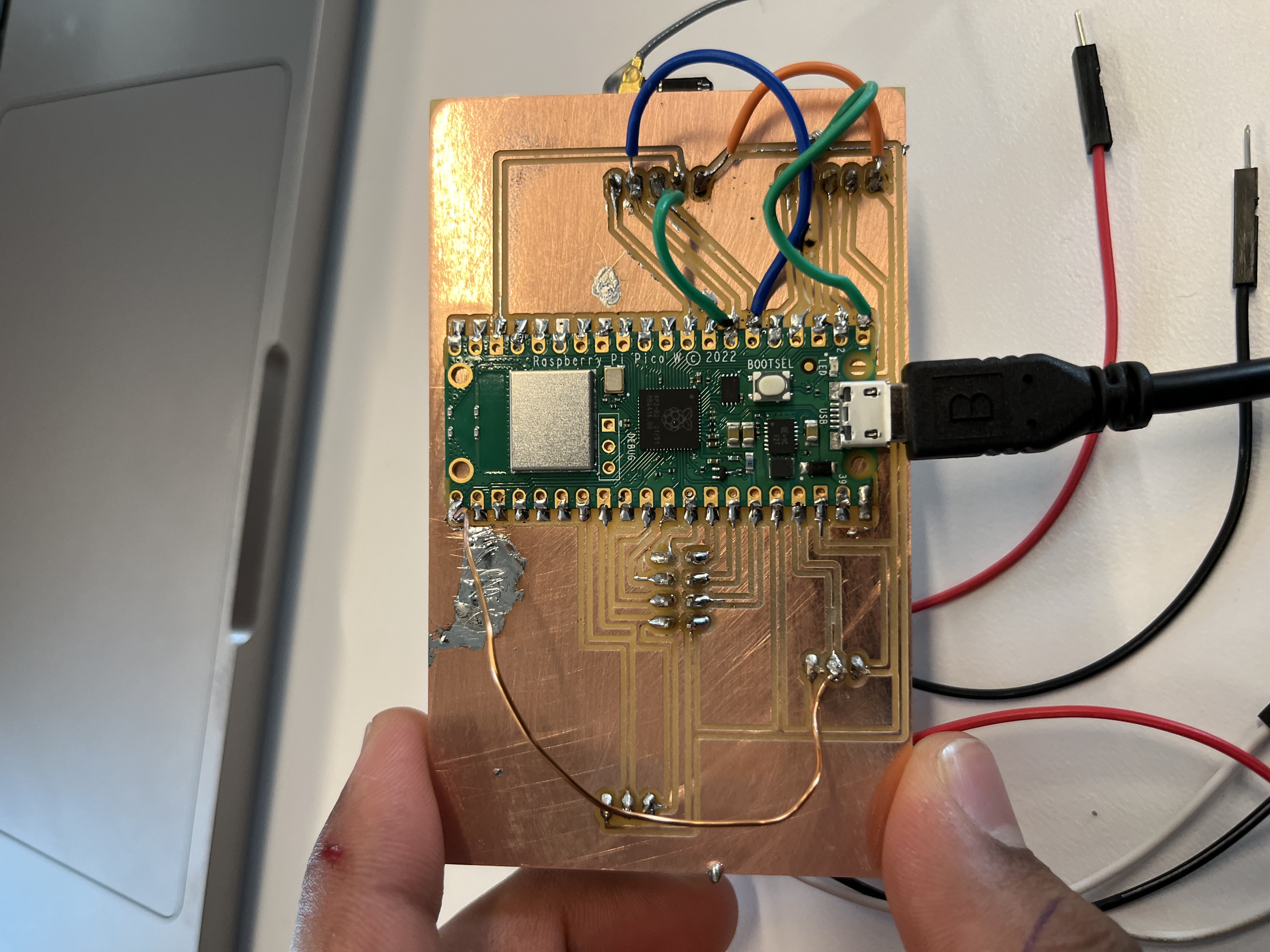
Furthermore, other pins in the compass were wrongly connected. There was also a microscopic crack in the copper traces, which had to be repaired with some solder.
This meant I had to use a number of jumper wires to bypass PCB routes, and disconnect certain PCB traces. The final board looks something like this:
After making all relevant connections, I then programmed the GPS module. See the code below, it prints out the latitude and longitude.
I then read from the GPS module, reading the latitude/longitude. The reason I was able to do so indoors at the EDS lab was because their is an antenna on the roof that streams down such connection to the 5th floor amongst other floors.
I was able to read these coordinates and verify that they were the same as building 36! Unfortunately I didn't capture video evidence of this working, but Anthony did see/confirm it working. I've included the GPS code downloadable below for reference. It is written in micropython.
Download the code here
I also worked on programming my compass module.
During my programming, the compass was not initially working. This was due to a short between physical pins 1 and 2 on the Raspberry Pico W due to a soldering accident,
as revealed by multimeter tests. These were addressed by resoldering the relevant pins.
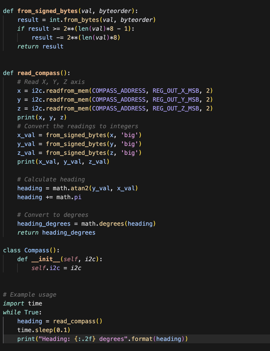
The module, a QMC5883L, was programmed with the following code.
The values I get are within +- 30 degrees of the iPhone compass values. These aren't as accurate as hoped, and unfortunately I don't have video proof on this, but I did show Anthony and was able to get it working on a PCB.
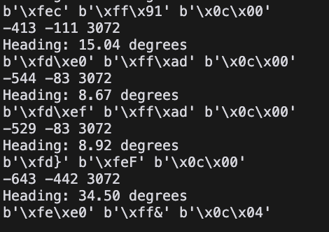
I have included the code below. What it does is that it reads the relevant addressed bits from the i2c channel being used (0 and 1 pins). It calculates the strength of
the magnetic field in the x, y, and z directions. Then it uses arctangent + trigonometry to calculate the exact bearing.
In the code here we do this repeatedly in a while True loop.
I've included a downloadable link for the code here