This week, we're designing a "parametric construction kit" using the laser cutter and some material (probably cardboard). It's kind of like LEGOs, except flat and there's no bricks. Oh, there's also a vinyl cutter assignment --- from what I've seen, it's a glorified sticker machine but I'd like to explore cooler use cases for it.
I want to create a modular-ish airplane construction kit that uses just press fit. I thought that'd be cool because it lets me experiment with airfoil shapes and enable quick repairs when this thing inevitably breaks.
What does this mean? The laser cutter is pretty good, actually its accuracy is on the order of several microns but the issue comes from the laser itself. Depending on the material and job configuration, it has an effective radius on the order of 0.3mm to 0.6mm (from my experimentation). This is known as kerf, and part of this week's tasks was determining this.
Now, 0.3mm is small but in a press-fit design this makes a world of difference, so we have to account for this in our design. This is where parametric modeling comes in because it allows parameters to be defined that alter the entire model. The CAD software I normally use, Shapr3D unfortunately doesn't support this so I had to learn Fusion360; this was surprisingly straight forward.
 Sketches of my design
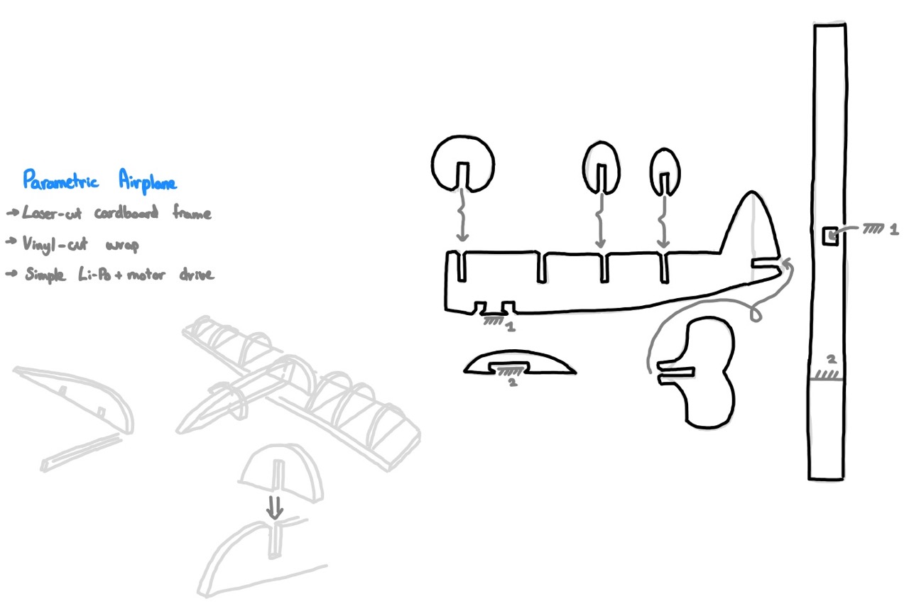
I want to combine both the laser-cutting and vinyl paper assignments into one project. I'll make the frame of the airplane from laser-cut cardboard, then skin it using vinyl. I used Shapr3D (simply cannot let go 😭) to quickly visualize this:
I'm so efficient with this tool I use it to sketch in 3D I don't want to learn Fusion360
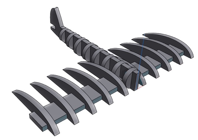
What I had in my head seemed to work in 3D, so I made a parametric model in Fusion360 and laser cut it...
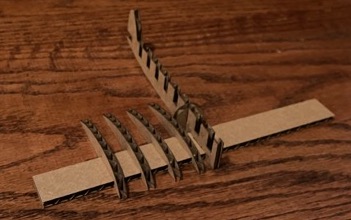 First test in the real world
...the results aren't great. The big problem is the wheels-to-body connection which is flimsily supported by the thickness of the cardboard (around 5mm). That means the wings swing side-to-side with little effort, and the large lever of the wings is too much for the joint. So, despite my best efforts tuning the kerf and other design parameters, this joint is fundamentally flawed. So:
I toyed with different iterations of the same wheels-to-body joint:
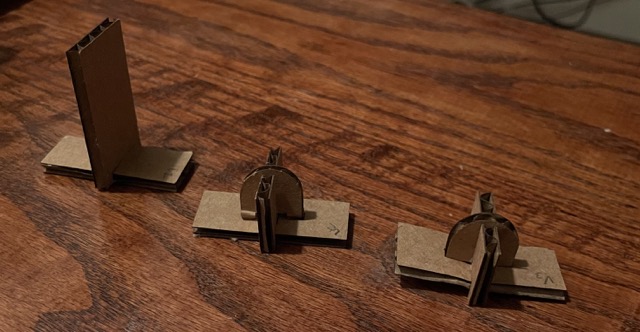 Joints, left to right: V1, V2, V3
V1 is what I had initially. On a smaller scale, it works OK. V2 is much better, but without perfect kerf configurations it still allows for the wing to tip or fall out. V3 is what I landed on: it's a mix of press fit and exploting the cardboard's compliance to make a really strong joint.
The thin-body approach is kind of neat to keep the weight down, but makes tuning the center of mass really hard. I went back to the drawing board and came up with this:
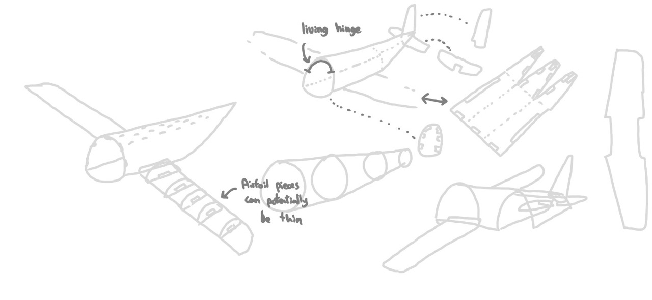 Sketches of my second design
And, of course, made a 3D version in Shapr3D:
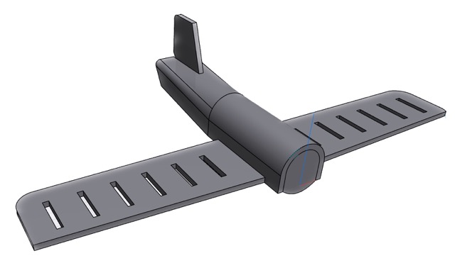 Visualization of the new design
The radical change here is that the body has some volume and cavities for placing weights (i.e. to balance it). So, I made the model parametric in Fusion360 and gave it a try:
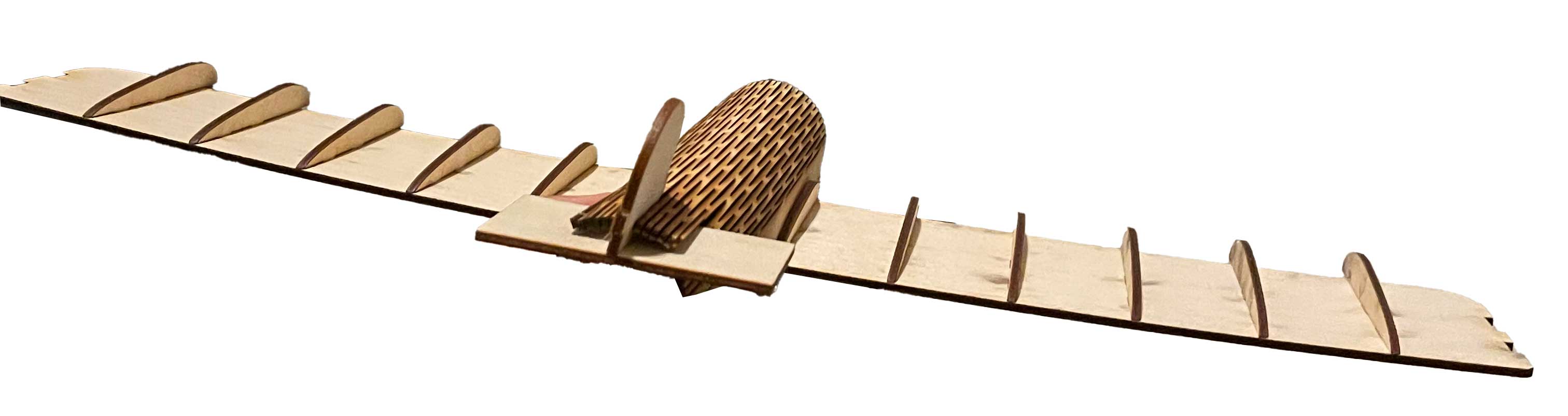
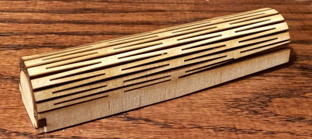 Testing the body of the plane on this new design
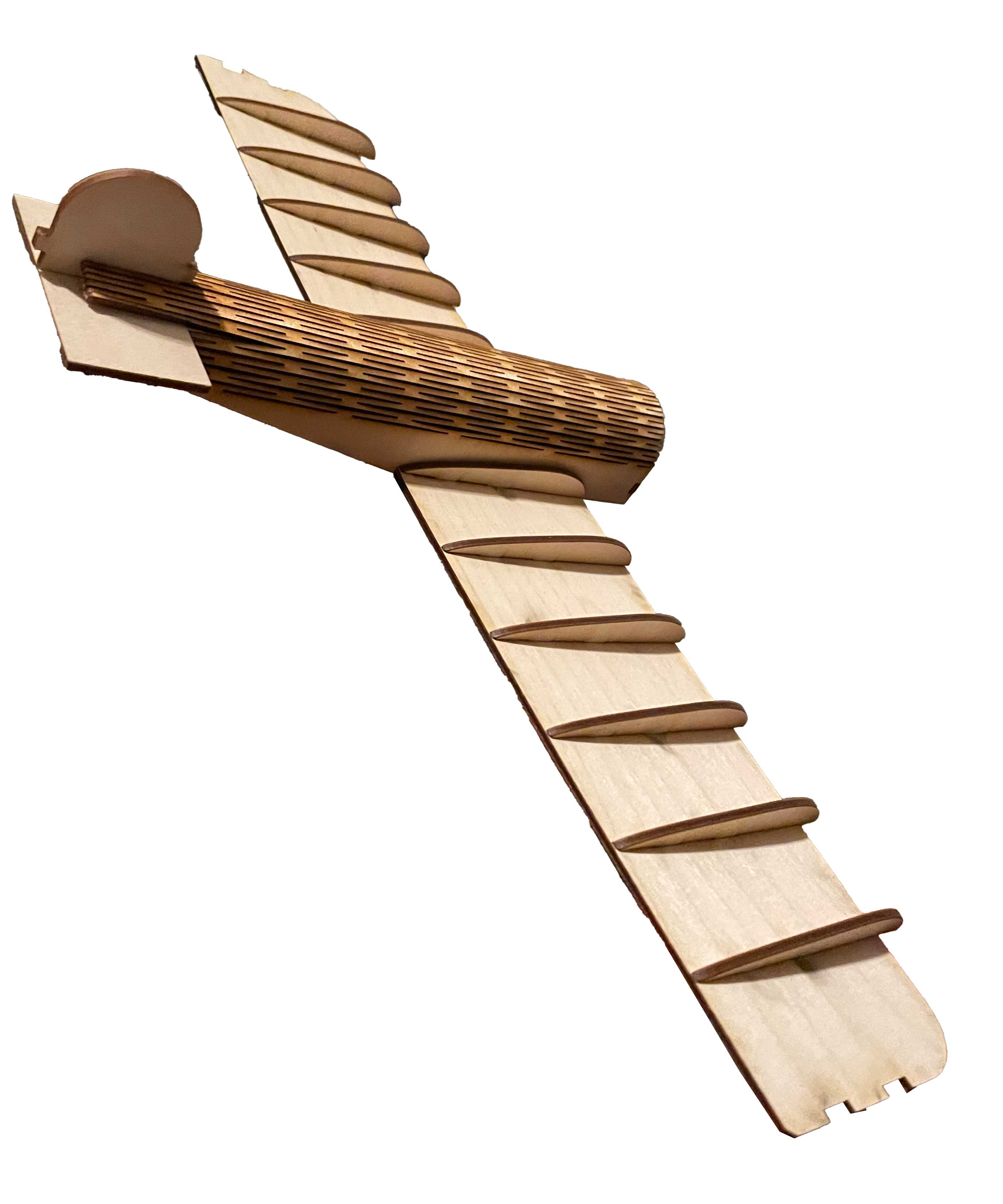
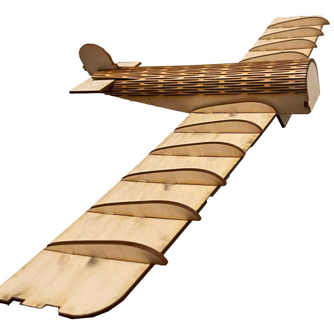
The largest take-away here is the curvature despite this being plywood. I accomplished this using a "living hinge," and the result is very rigid. So, I doubled my model in size and continued designing.
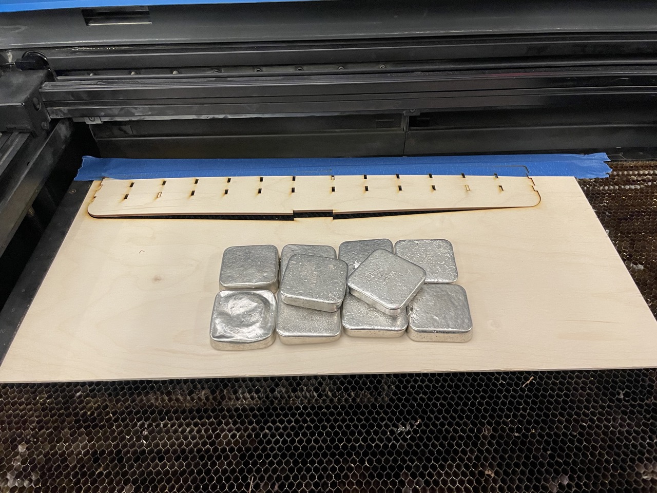 The wings were too large and curved to cut, so I had to use this funky setup
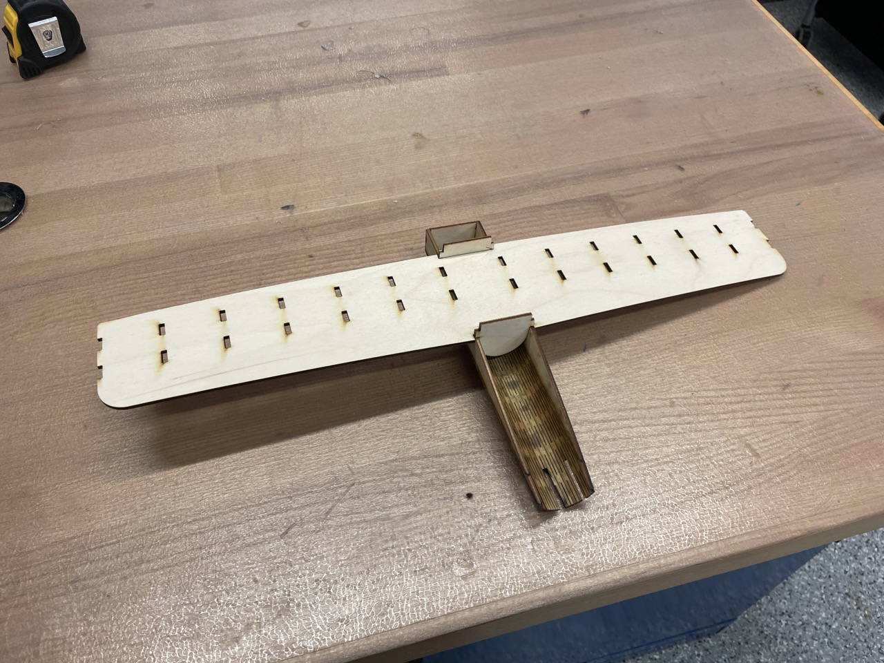 Underside of the plane, mid-construction
So unfortunately I ran out of time to make the cool vinyl skin for the plane idea I had, but settled for something in between:
