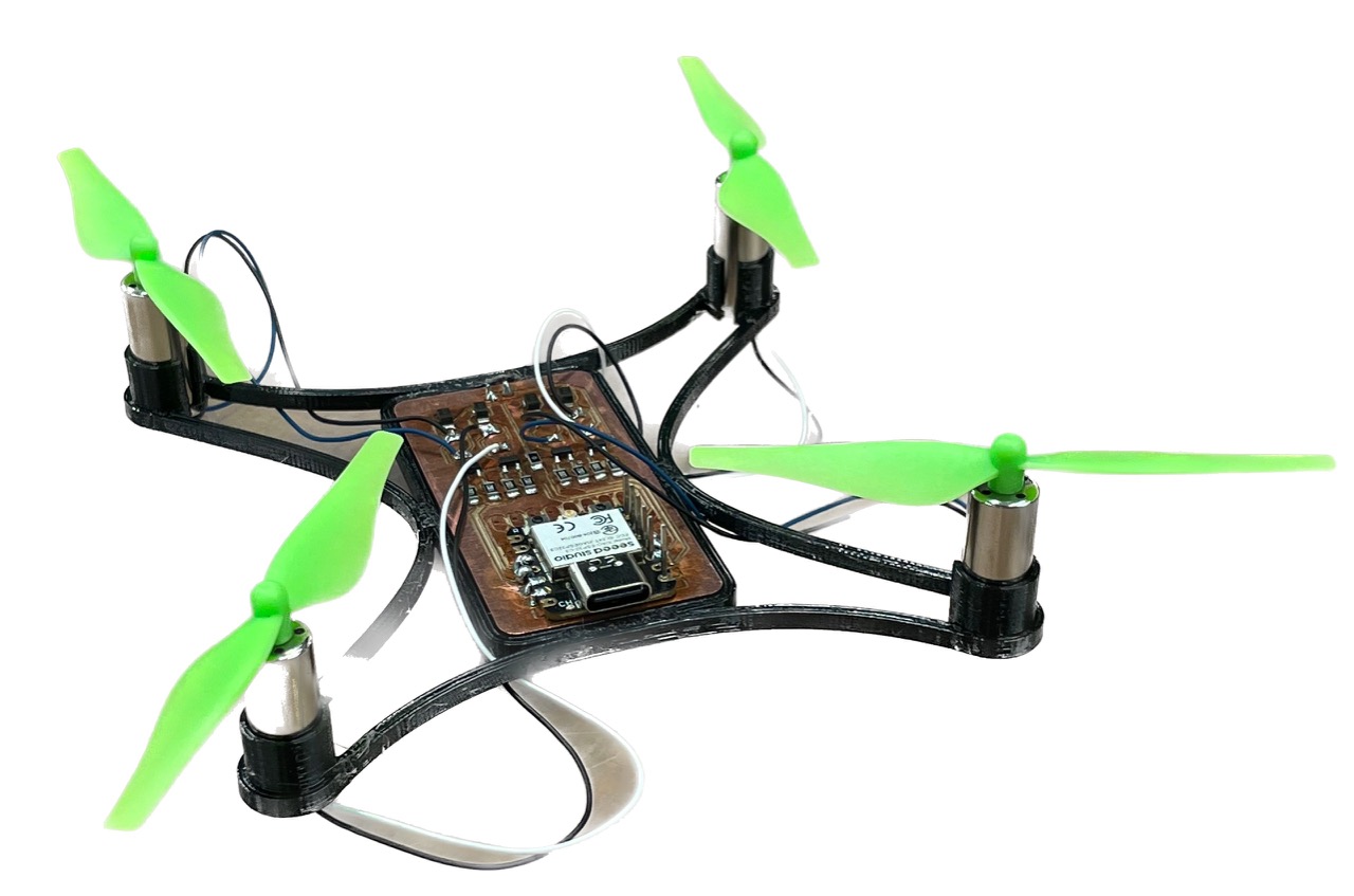
This week I'd like to build and program a quadcopter. You may ask: it seems everyone these days is making drones, isn't it just about buying a couple of motors and a kit? No, I'd like to push myself and make every component of a flight controller from scratch1.
What does that include? Motor speed controllers (x4), RF communications, inertial unit and a program to bring them all together.
1Something something apple pie, invent universe or whatnot
This will be my second time attempting this exact project. Last I tried, I was a freshman and fully prepared to fail my embedded systems class for a cool, over-ambitious final project.
Above is the gist of my development. It was with that project that I first learned to CAD, so most of my time went there and the electronics were more of an after thought (hence the nightmare through-hole stuff going on). And, well, it "flew" once. Then the crash shorted the spaghetti mess going on at the base and that was it.
So this time around (well actually everything is different now because I lost all the files), I'm taking a much better approach: PCBs! And it so happens that this week's assignment is designing a circuit in an EDA software that we'll bring to life next week.
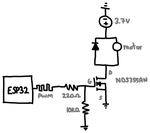 Sketch of a single motor controller circuit
The first part of this PCB is the motor controller, which revolves around the idea that we'd like a microcontroller to modulate the speed of a motor but its pins cannot directly power it. That's because motors are really power hungry and one with load (let alone four) will definitely not work and perhaps fry the on-board regulator.
So we offload that task to a voltage controlled current source, such as a MOSFET. The MCU's pins can regulate voltage (via PWM), and the MOSFET will comfortably allow a lot of current to fly through it. I used the NDS355AN because it's what we have in lab, but let's double check its ratings to give the illusion of choice.
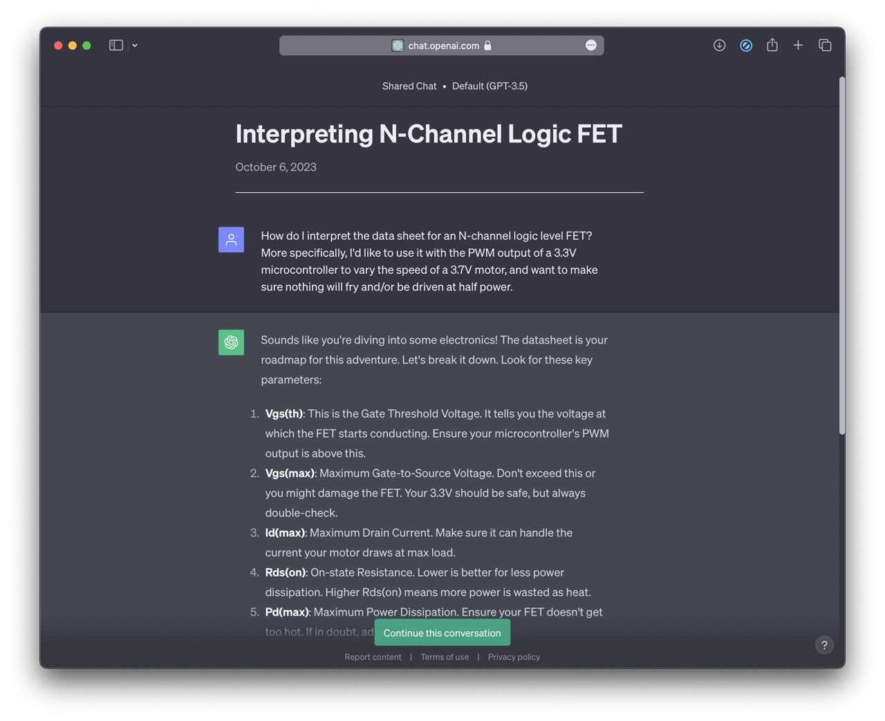 I asked ChatGPT how to interpret a FET datasheet
Here are the important design requirements for this particular application:
And now some details/decisions about my circuit for anyone wondering:
I tried using Fusion360's circuit and PCB design suite. It sucked, never again.
I tried KiCAD next and had a much better experience. The first task was replicating my circuit digitally:
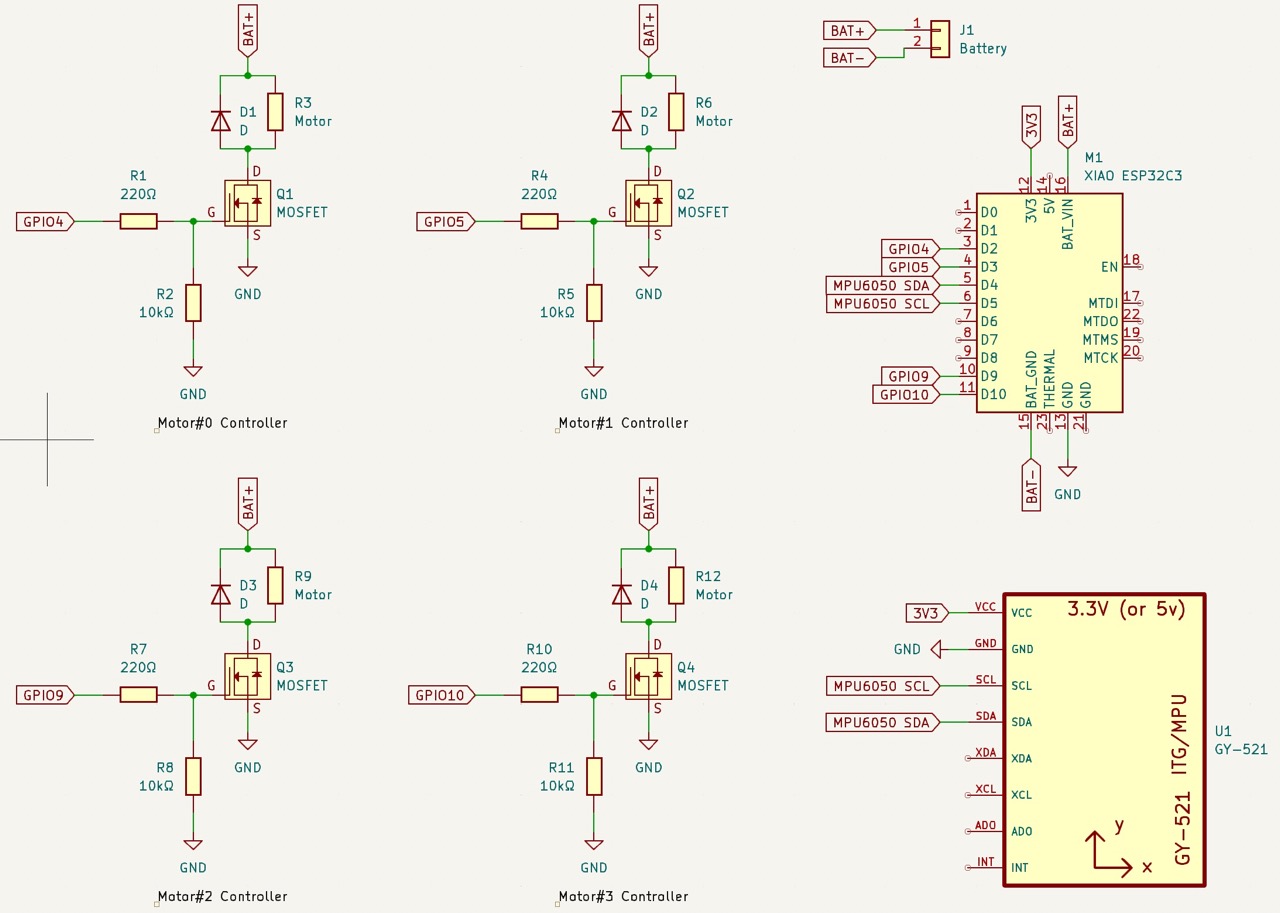 Complete circuit
Then I need to arrange everything in circuit board land:
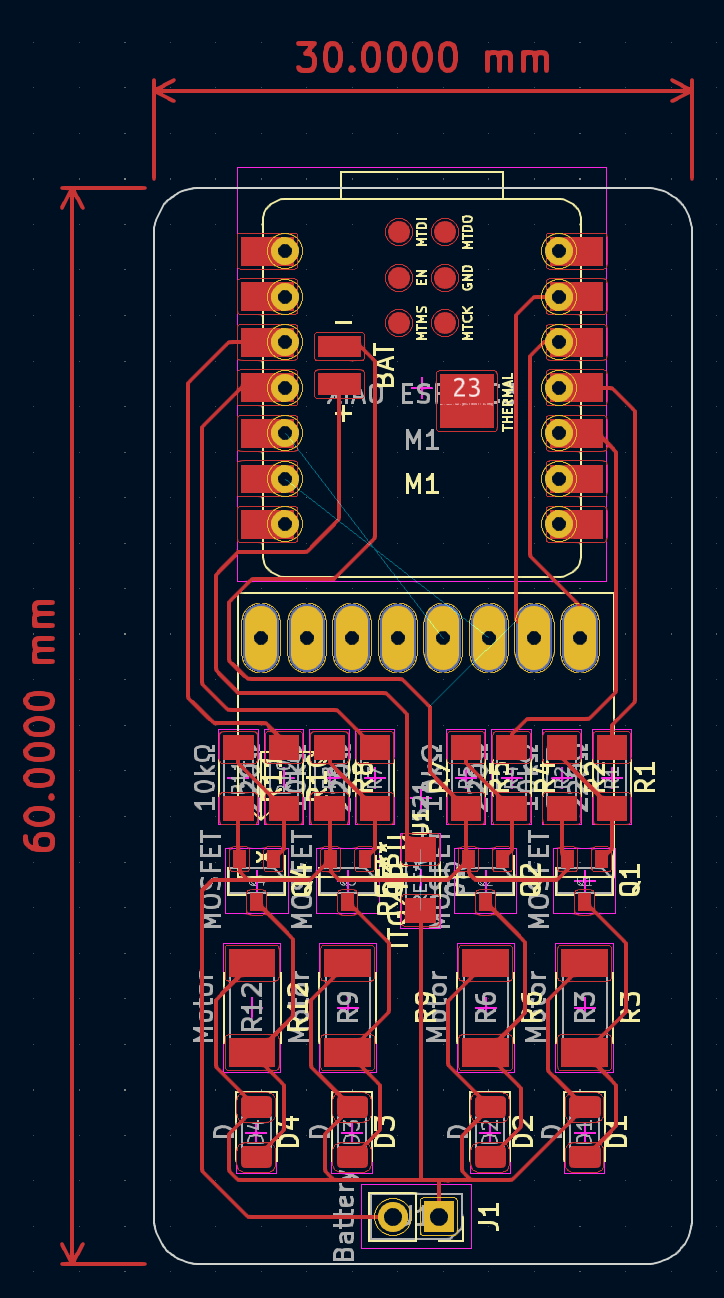 PCB design I came up with
The drone frame is very simple and fitting the motors and board takes advantage of the PLA's compliance. I got this idea from here. On a Prusa this took 24mn to print, and this design is about 30mn of work in Shapr3D. So the frame only took an hour; neat!
 The frame is flat, so there's only one sketch
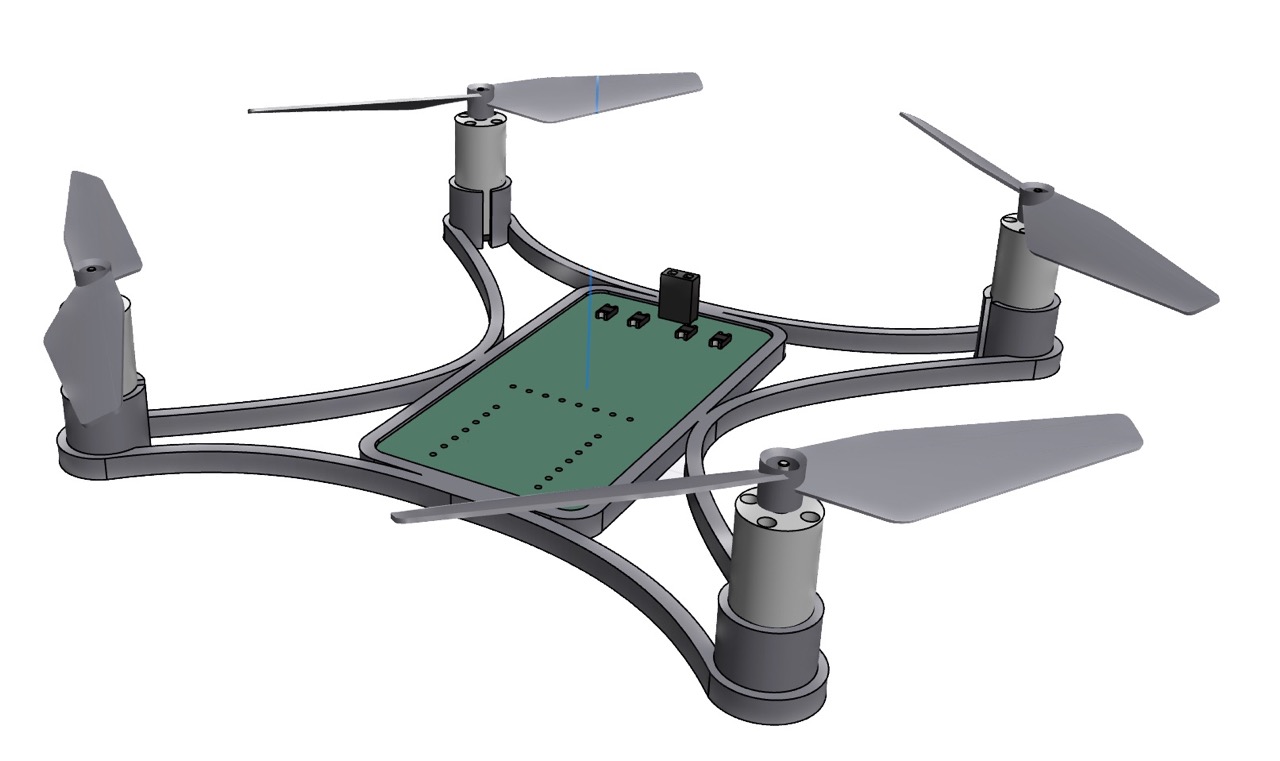 Visualization of the final drone. I used these two models.
This is technically next week's assignment, but I wanted to get a head start. In the EECS lab section, we're using the Bantam Tools CNC mill.
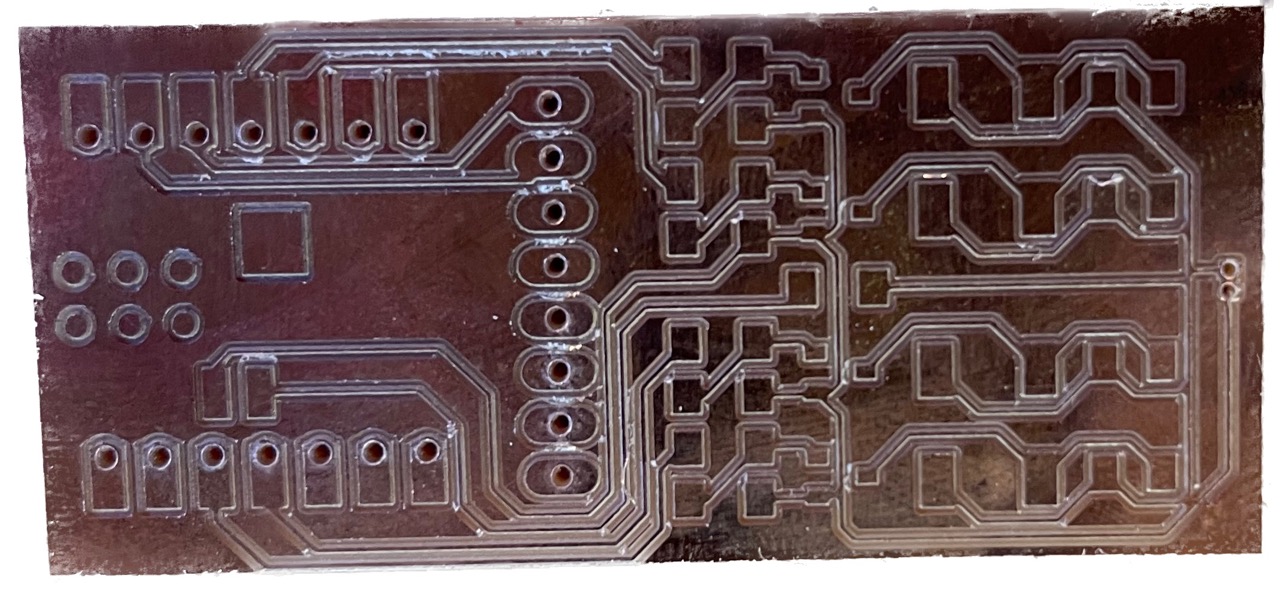 One of the earlier boards I milled
I used SMD components, solder paste and a hot plate/air station to assemble everything.
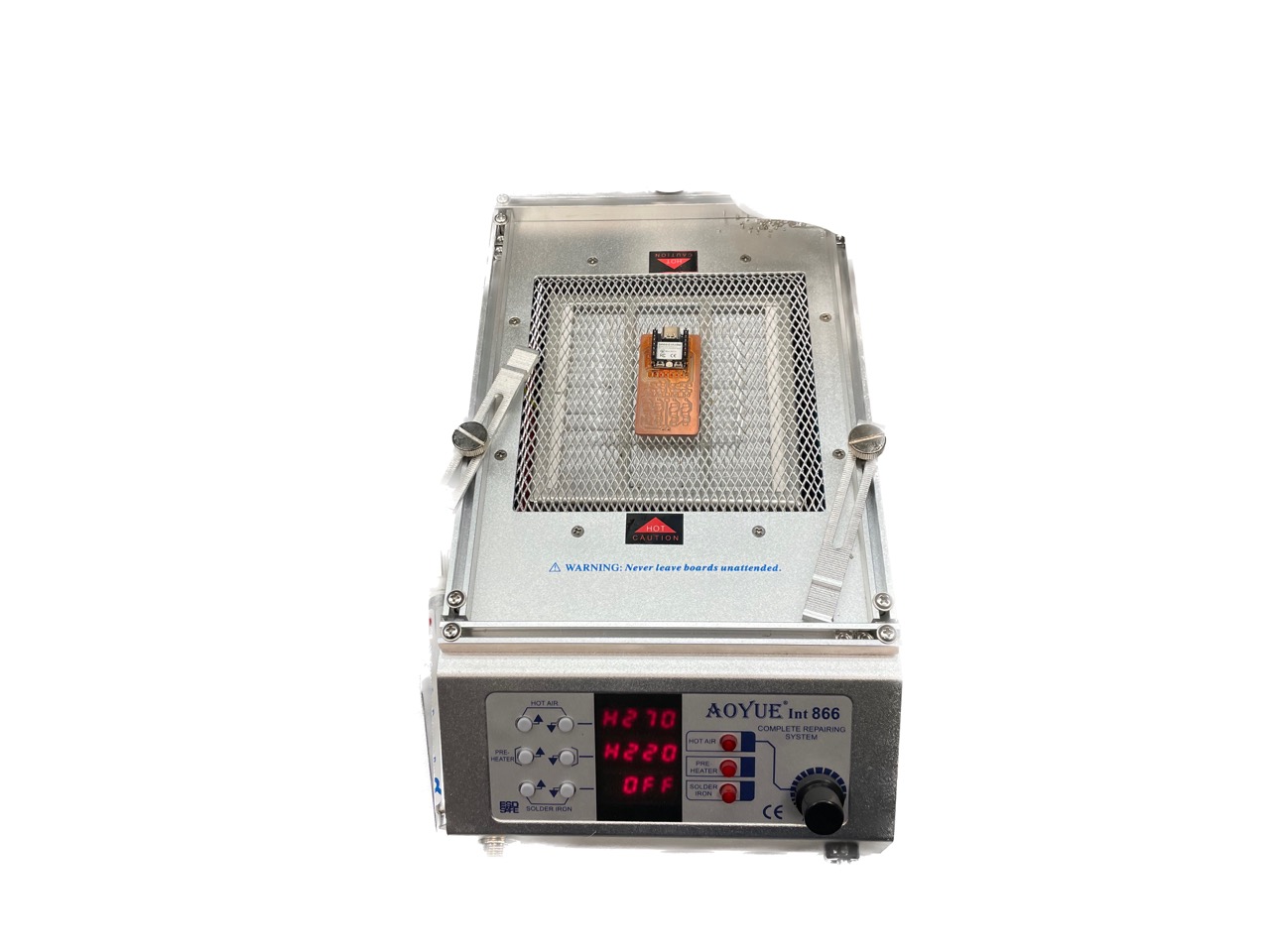 Hot air station I used
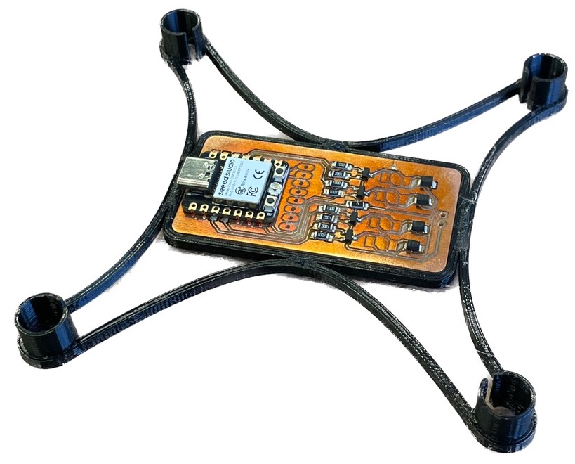 All the SMD parts put together!
What. A. Pain. Writing about this in full details would probably be very boring but the takeaways of my (and Anthony, who helped a ton) suffering is described here:
I learned these tips the hard way when all but one of the motors worked (the last would always be on). It turned out that the pin controlling that motor was shorted to the battery (via trace under the ESP32 that I can't see) so the gate was always driven high. This is fixed by routing that motor to a different pin (slow, painful) or following the advice above (easy, straightforward).
Now, I still have all but one working motor. For some reason, one of the controllers stopped working. I have no idea why.
Next week I'll be fixing the motor controllers, adding an IMU and hopefully getting this thing to fly!