This week I'm making a bass guitar; well the electronics part of it that is. Eventually I'd like to build the full bass guitar entirely on MIT's money (except for the strings). To that end, just about every component is "do it yourself." So I'm starting with what most DIY guitar projects don't do: the pickup.
What is a pickup? It's a coil of wire which picks up small vibrations in the guitar's string (faintly audible, but is a changing magnetic field) via Lenz's law. It's also got permanent magnets within to magnetize the ferromagnetic strings (otherwise none of this would work). That electrical signal is then sent to an amplifier to be boosted and converted back into sound. So electric guitars work by mechanical (vibrations) → electrical (pickup) → mechanical (sound).
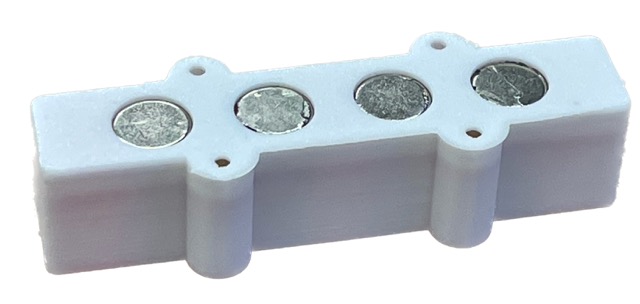
There are a few different types of basses with their respective pickups; I'm making a jazz bass and will be replicating the form factor of this commercial pickup in case everything goes wrong (so I can continue with this project).
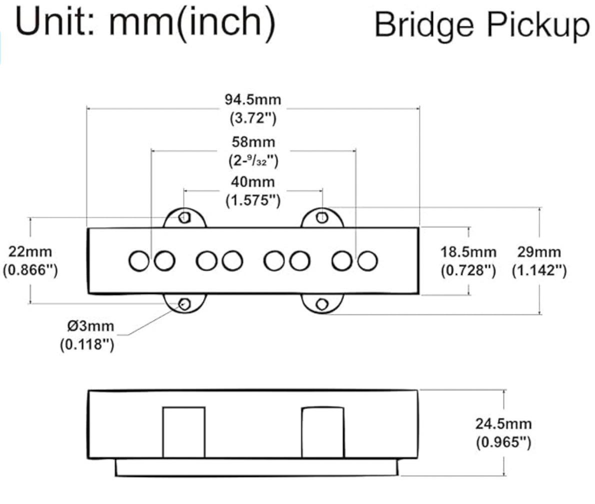 Dimensions for this specific J Bass Pickup, courtesy of Amazon
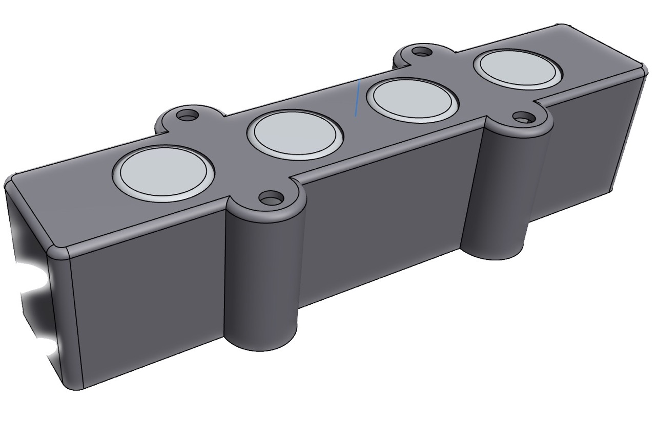
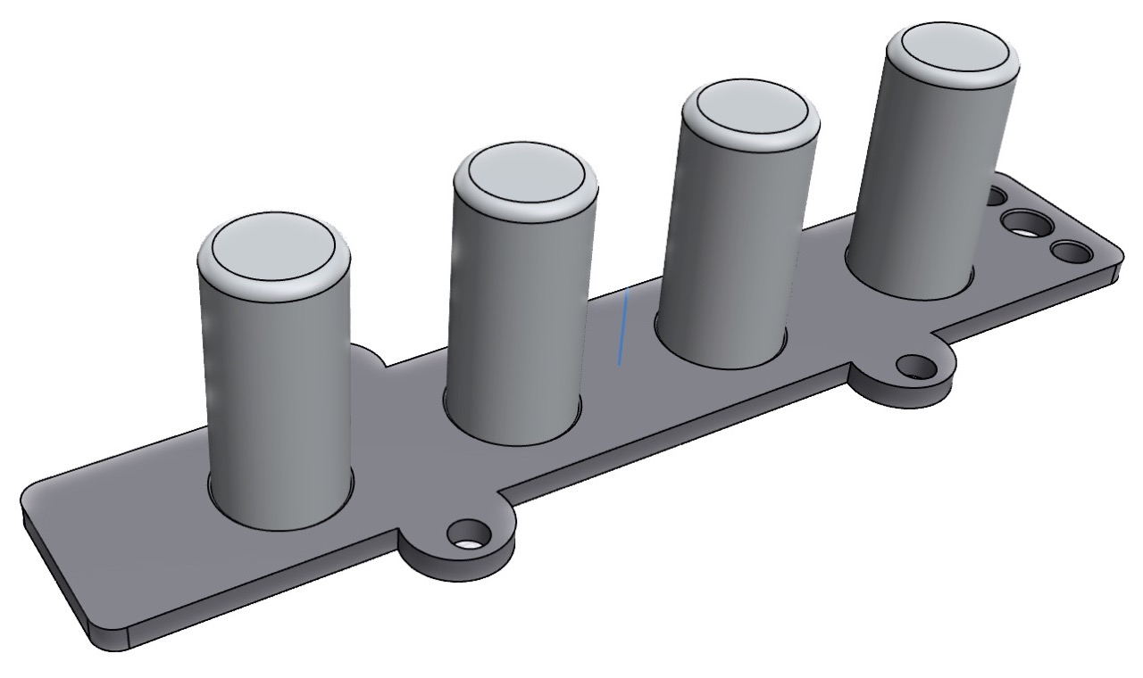
As per usual, I'm starting with a CAD of the project.
 One of the permanent magnet holders, called "flatwork"
 Casing for the pickup, mostly for aesthetics
This component holds the magnets in place at the top and bottom. These are typically manufactured but of course this project requires spending no money what so ever. So I tried 3D printing it, and failed miserably. Despite 100% infill, the magnets are too strong to be held and long printing times aren't ideal for playing with tolerances. So the next approach was laser cutting which, albeit not working first try, made iterating very easy.
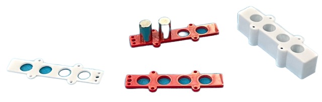 Left to right: PLA flatwork, acrylic flatwork, casing
 Final flatwork configuration
 Graveyard of my many iterations
Most bass pickups are wound ~8000-9000 times, which (thankfully) I will not be doing by hand. Instead, I opted for a setup with an electric hand-drill.
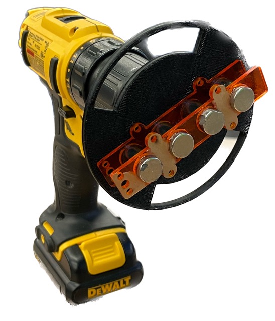
The black part above is 3D printed, but has a bolt and nut running through it to take all the forces. It also has the advantage of magnetically mounting the pickup (no double-sided tape!).
The only issue with this setup is that hand drills don't count the number of rotations. Oh, and I haven't fulfilled this week's assignment yet. So I'll be taking a quick detour in building a rotary encoder.
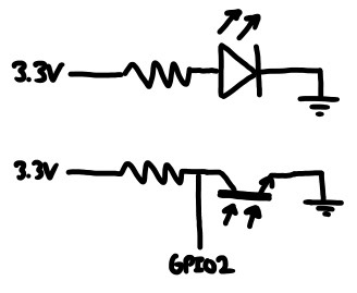 Circuit I'm making
This is pretty routine by now. I start by sketching the circuit on paper, design it in KiCad and mill it on the Other Mill.
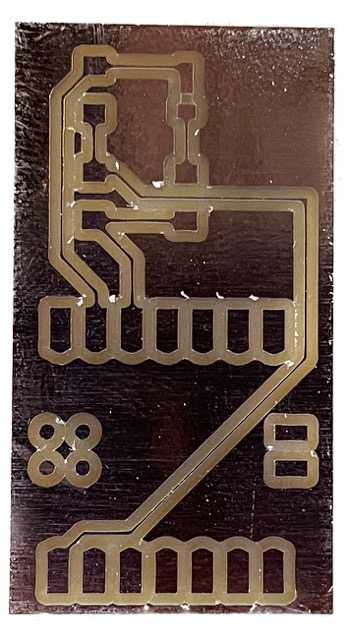 PCB milled almost exclusively with 1/32" end mill, so it turned out really nicely
 Everything assembled
This is a reflective optical encoder. It works by shining a light against a disc with a alternating reflectivity and a phototransistor in a voltage divider configuration is used to count rising edges (rotations).
I'm dividing the phototransistor with a 1kΩ resistor. Against white vinyl, the contrast is high enough to be picked up as a digital signal. So my code can use interrupts and becomes super simple:
#include <Arduino.h>

volatile int num_edges = 0;

void cb() {
    num_edges += 1;
}

void setup() {
    Serial.begin(9600);

    pinMode(A0, INPUT_PULLUP);
    attachInterrupt(digitalPinToInterrupt(A0), cb, RISING);
}

void loop() {
    Serial.println(num_edges / 2);
    delay(5);
}
I also double checked these readings against a mechanical winder. It was 100% accurate every single time I tried (yay!).
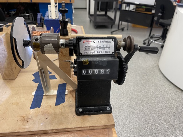 Baseline mechanical winder with rotary counter
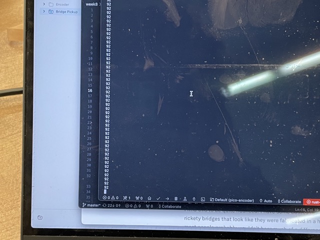 Versus what my rotary encoder is saying
I designed a couple more parts for a makeshift coil winder.
 Suuppeer smooth bobbin holder to prevent getting stuck
So now it's just a matter of rigging everything up and pressing the trigger on the hand drill, right?
In reality, my setup was too jank and the whole process was very manual. I had to untangle the wire every dozen turns and the 36 AWG wire I used was too thick to reach the desired number of coils.
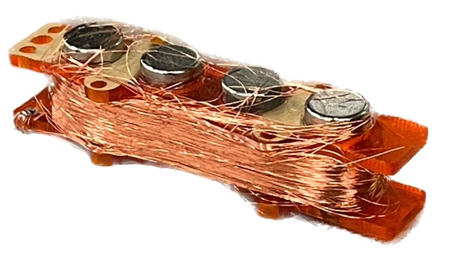 First attempt at winding a pickup
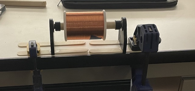
I tried again with smaller magnets (which occupy less space = more windings) and better technique, which looked a little better:
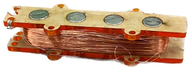 Second attempt
It's still not very clean but I didn't have time for a third attempt.
The next step (very important!) is potting the pickup. This protects the coil from damage and electrical noise and the pickup didn't work at all without this. Typically this is done with bee's wax, but I used hot glue :P
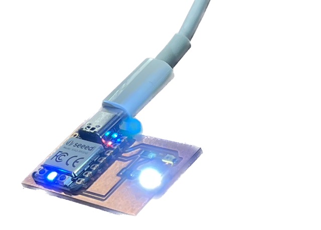
I first tested this against an electric guitar and... it worked!
So I went to a sturdy table and made a "clamp guitar" which consists of the bare minimum for a working guitar. I used these 3D printed tuners and made the bridge out of aluminum; again, I want to spend $0 on this project. The only purchase were these bass guitar strings.
Here is the final product (sound up!).
I'll be continuing this project independently and posting the progress on my personal website. I plan to 3D print most parts and cast some out of metal. The body will be CNC milled and made from free wood from various maker spaces.