End Effector
Machine Building
Summary
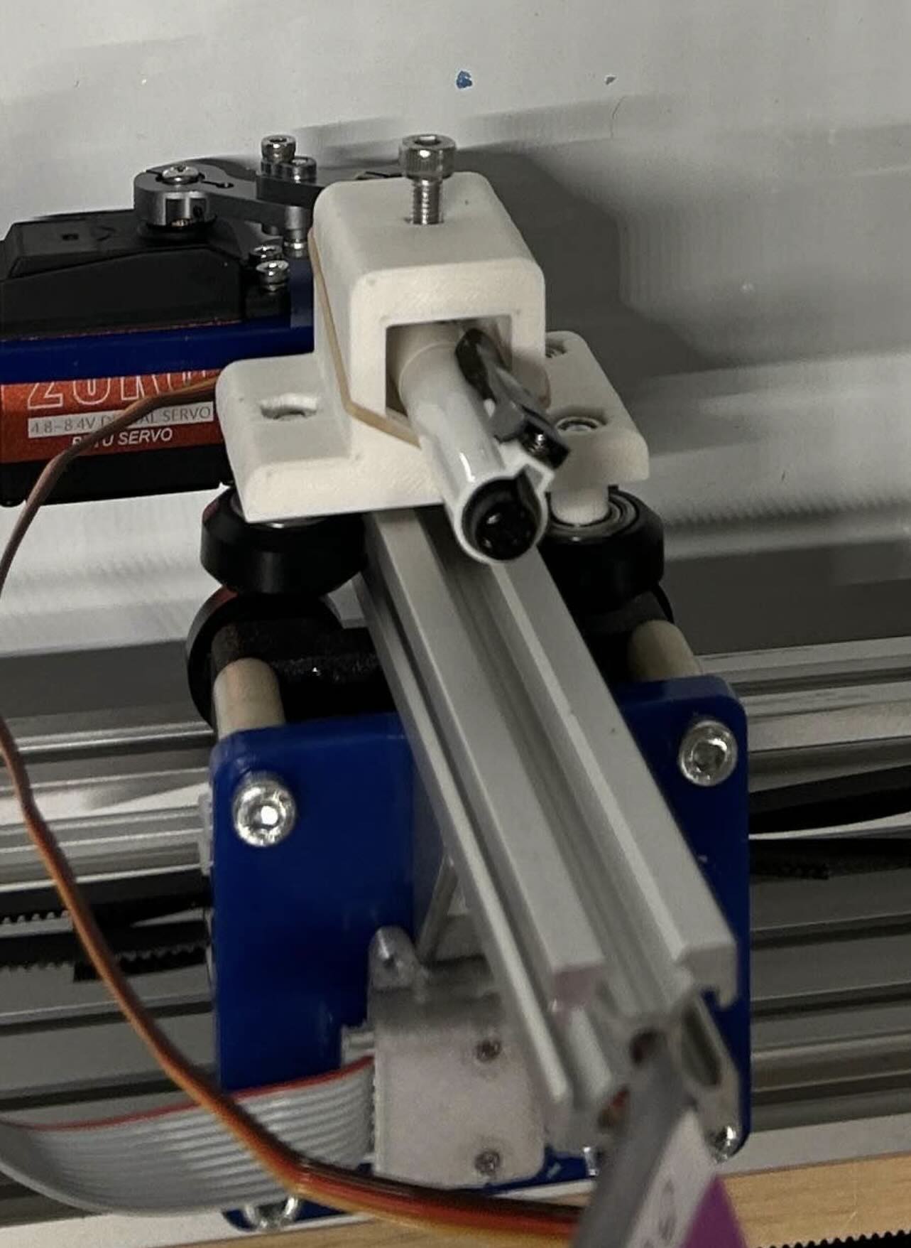
For the drawing robot, we developed an end effector that could write. Qualitatively, this meant that it should be able to put the marker down and to lift it up. To take it a step further, the end effector would be able to alternate between the eraser and the marker.
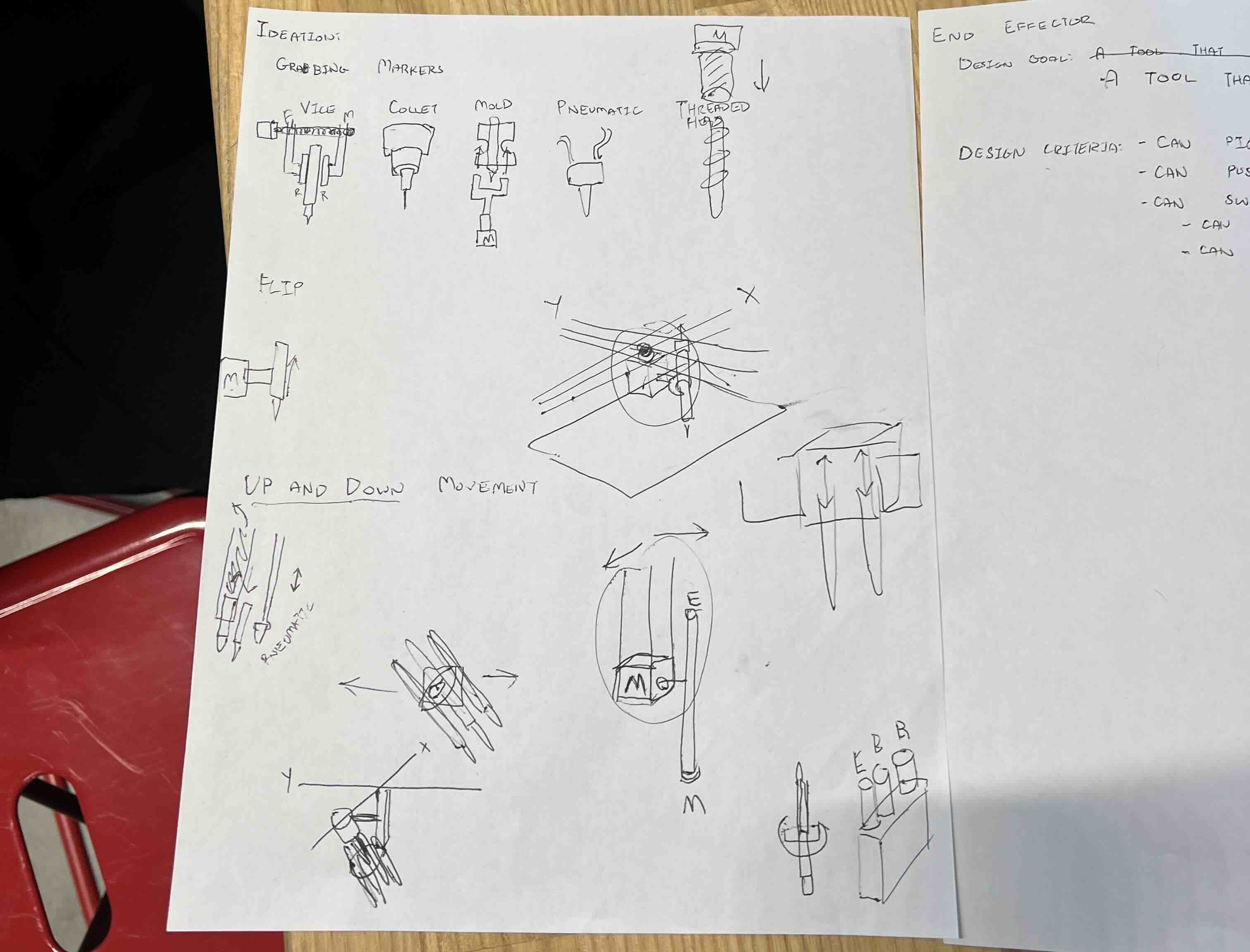
This required consideration of mechanisms with which to make the marker traverse the Z-axis to move up and down, and mechanisms with which to grab and release the marker to swap it. We explored vice grips, collet chucks, claws, pneumatics, screw mechanisms, and even a rotating barrel mechanism, finally settling on a design where one eraser and one marker actuated on racks opposite of each other about a pinion.
We 3D modeled several casings for the end effector, iteratively improving the model as we encountered difficulties with the design. In keeping with spiral development, we started with a simple marker holder before implementing the rack and pinion mechanism. Iterative improvements include thickening the walls of the end effector to prevent it from bending due to the mechanism, correcting the diameter and width of cutouts for the writing tools and the servo, and finally finely adjusting the dimensions on the end effector as a small touch-up.
Ideation & Brainstorming
Key considerations, rotation mechanisms:
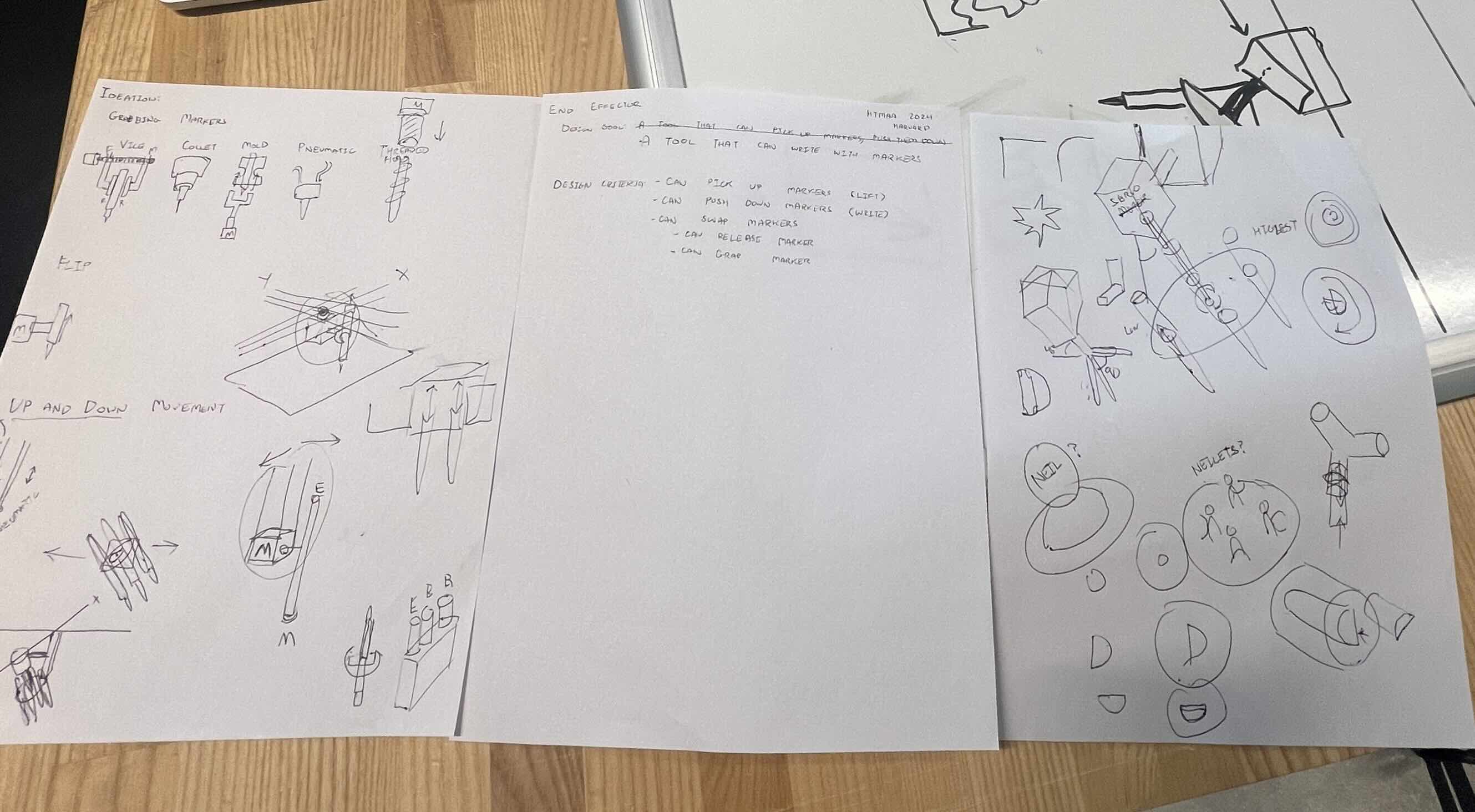
Grabbing markers, up-and-down movement:
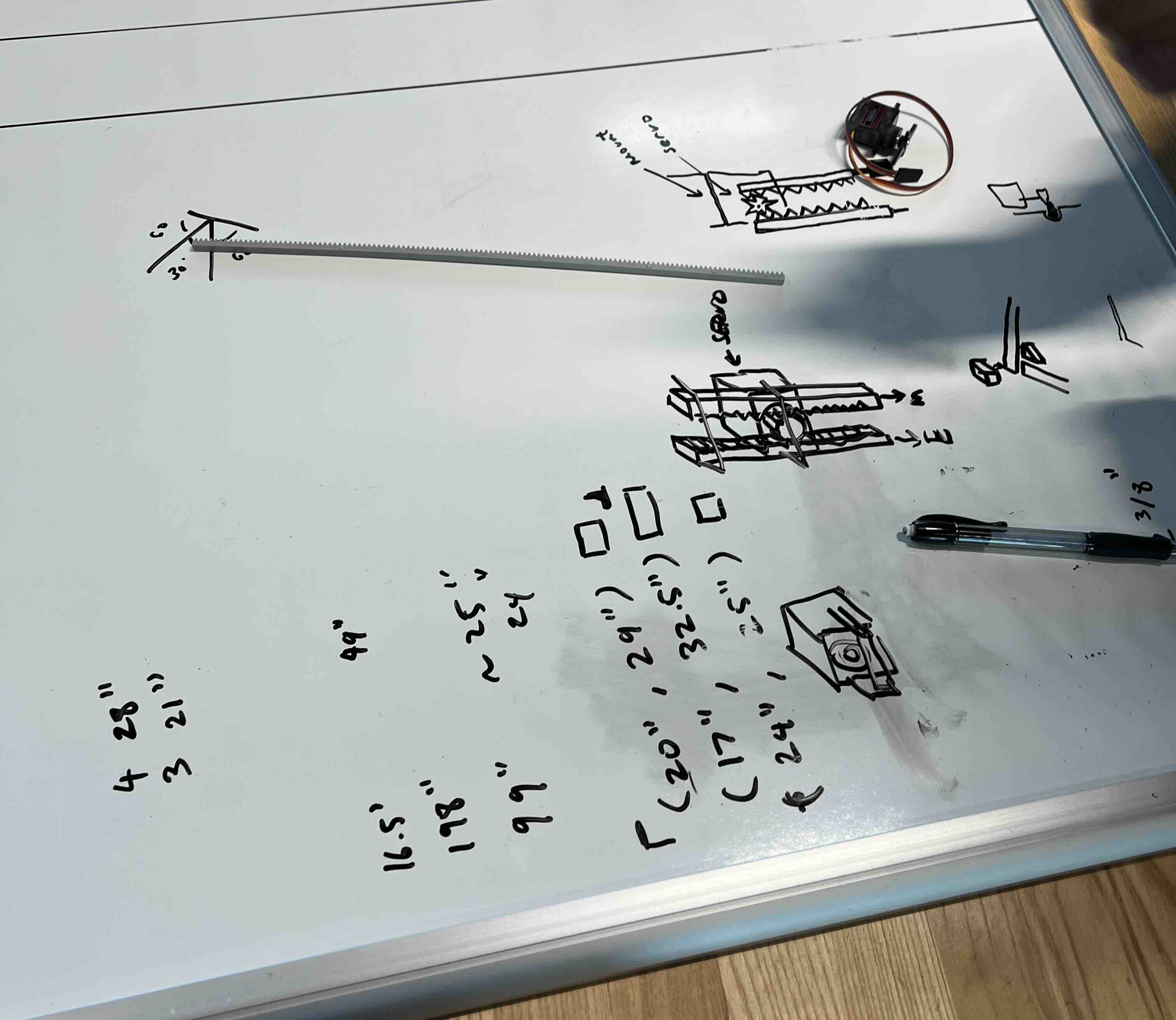
Servo & rack-and-pinion mechanism (ultimately went with this idea):
Details
For the end effector, we wanted to enable both drawing and erasing by moving the marker and eraser up and down. Initially, we explored using collets to secure the marker and eraser but decided against it due to the complexity and time required for design and fabrication. Another idea was to manually exchange the marker and eraser, though this proved inefficient. Alex proposed a more effective solution: using a servo motor with a rack-and-pinion mechanism. In this design, the servo motor twists a pinion gear, engaging linear teeth on racks positioned on either side of the gear. This converts the angular motion of the gear into linear motion, allowing one rack to move up while the other moves down. This configuration, powered by a single servo motor, efficiently alternates the positions of the marker and eraser, simplifying the overall system.
To support this mechanism, we created a housing for the servo and rack-and-pinion assembly, designed to mount securely to the gantry system. The design process included two different CAD experiments to test and refine the system. Each iteration focused on optimizing the functionality and integration of the assembly within the larger framework.
The development process for this project involved multiple iterations and careful refinement of the design. The ideation phase began with brainstorming key considerations, such as how to grab the marker, alternate between marker and eraser, and control vertical movement. Several approaches were explored, including using a vice, collet, mold, or pneumatic mechanisms to secure the marker. One unique concept involved a rotating disc to switch between tools, but ultimately, we used one servo to control the up-and-down movement of the marker and eraser for efficiency. The team decided to 3D print a casing to house the mechanism, with initial iterations focusing on achieving the right fit and functionality.
Iterations
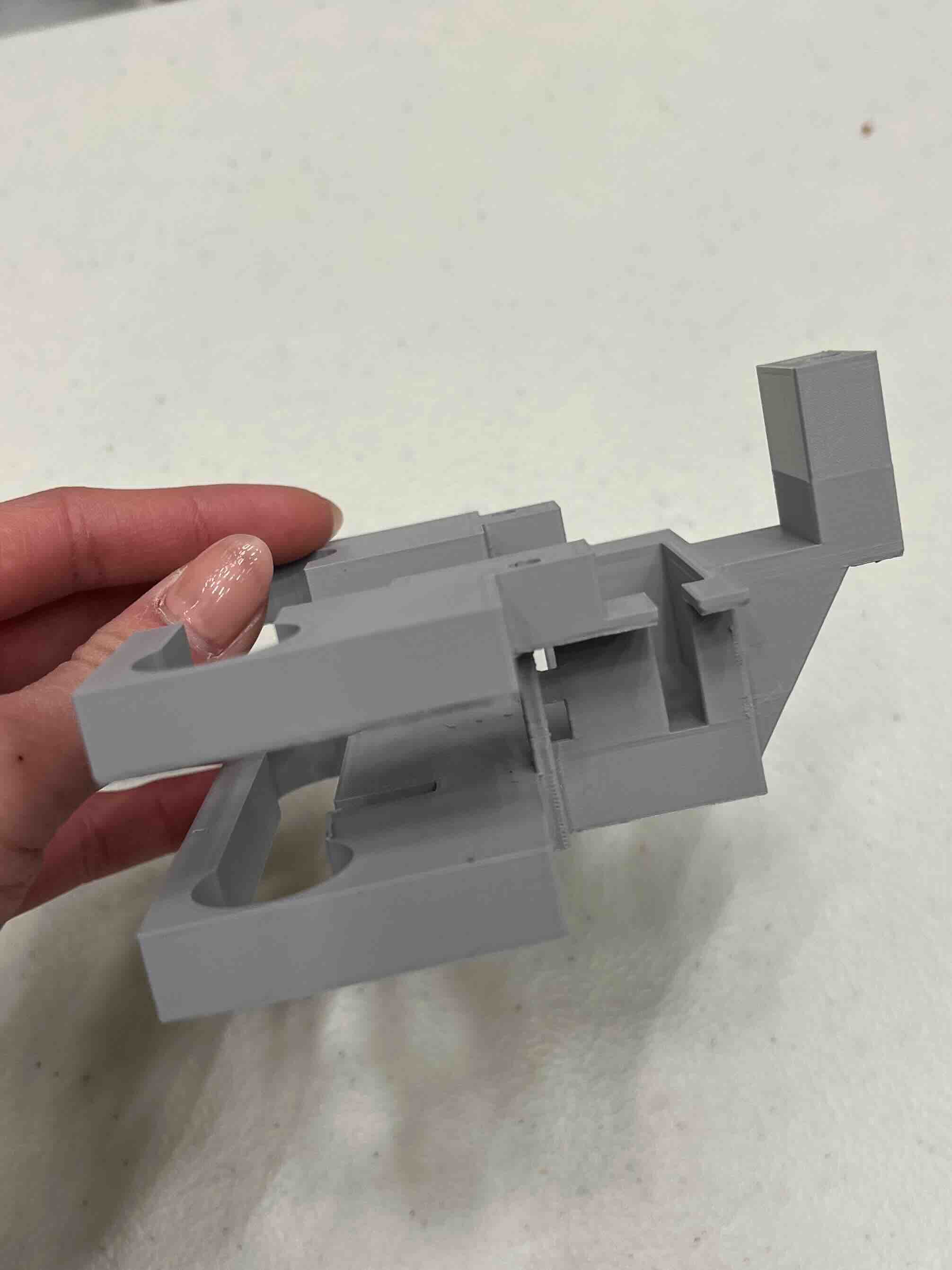
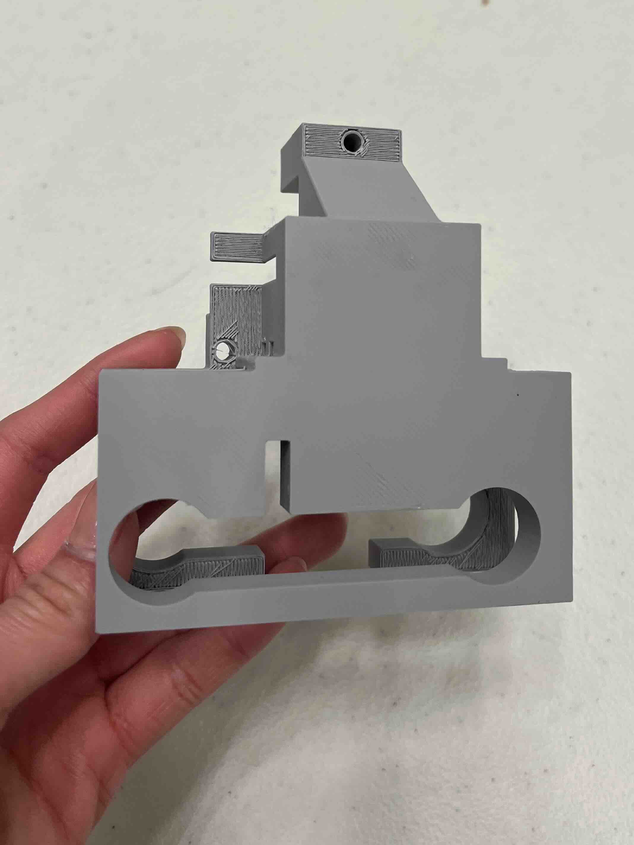
In the first iteration, the walls of the casing were too thin, causing them to bend under stress. The second iteration introduced a holder with the wrong diameter, making it unable to secure the pens, and lacked cutouts for attaching the servo motor. The rail also was lower than the moving cart, creating misalignment issues. In future iterations, we adjusted the parameters and used thicker walls.
Here is an example of one of those iterations:
Final Version
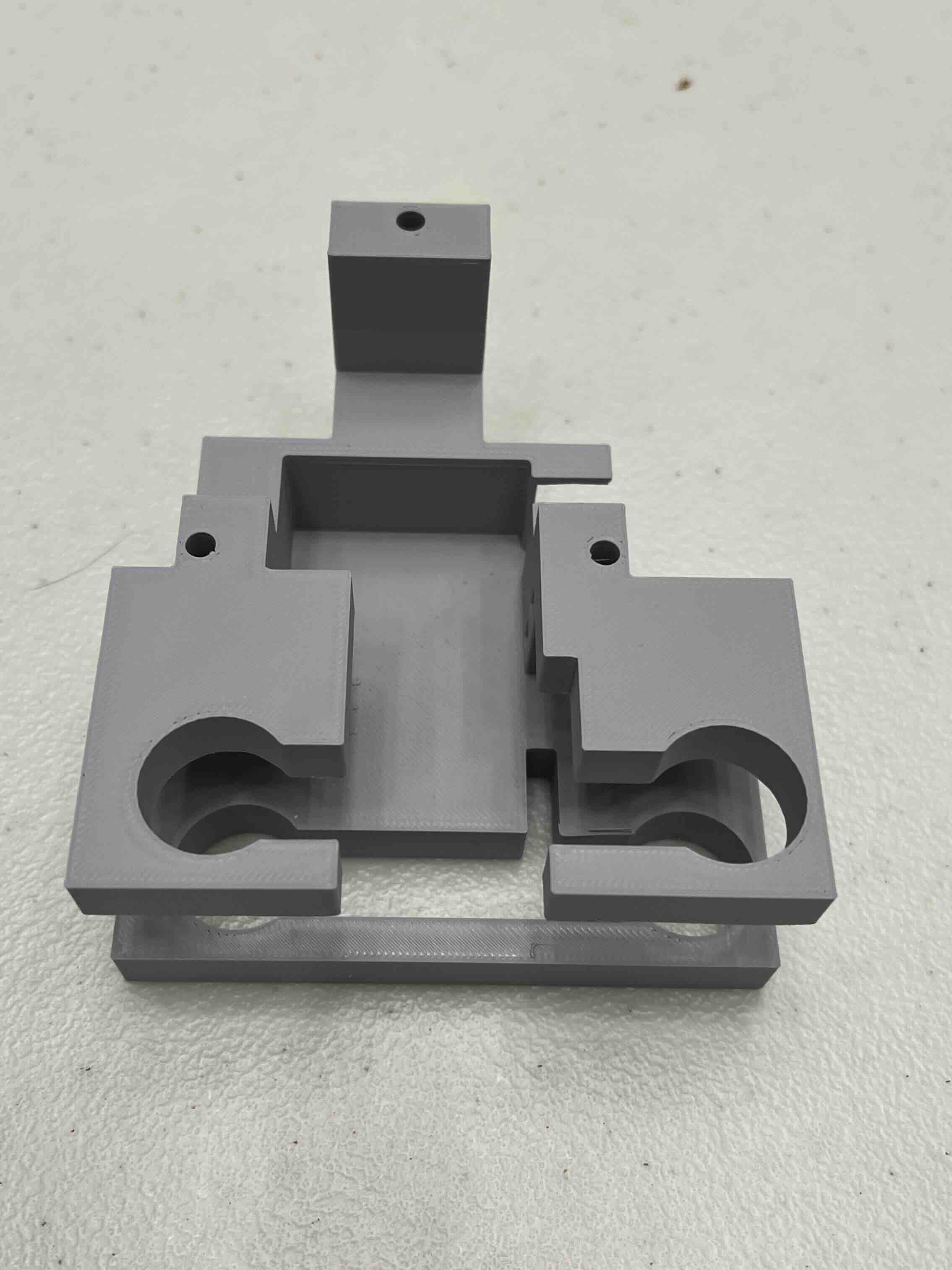
We ended up with this as the final housing (we used one servo that moves the housing up and down):

