Frame & Motor Control
Machine Building
Summary
The frame and motor control team’s main goal was to build a frame that could run the drawing cart in X and Y directions. For this, we referenced the CoreXY technique. While initially we were planning to build a large machine that would fit in a large whiteboard, we downsized after seeing the belt length, where the longest amounted to around 16.5’.
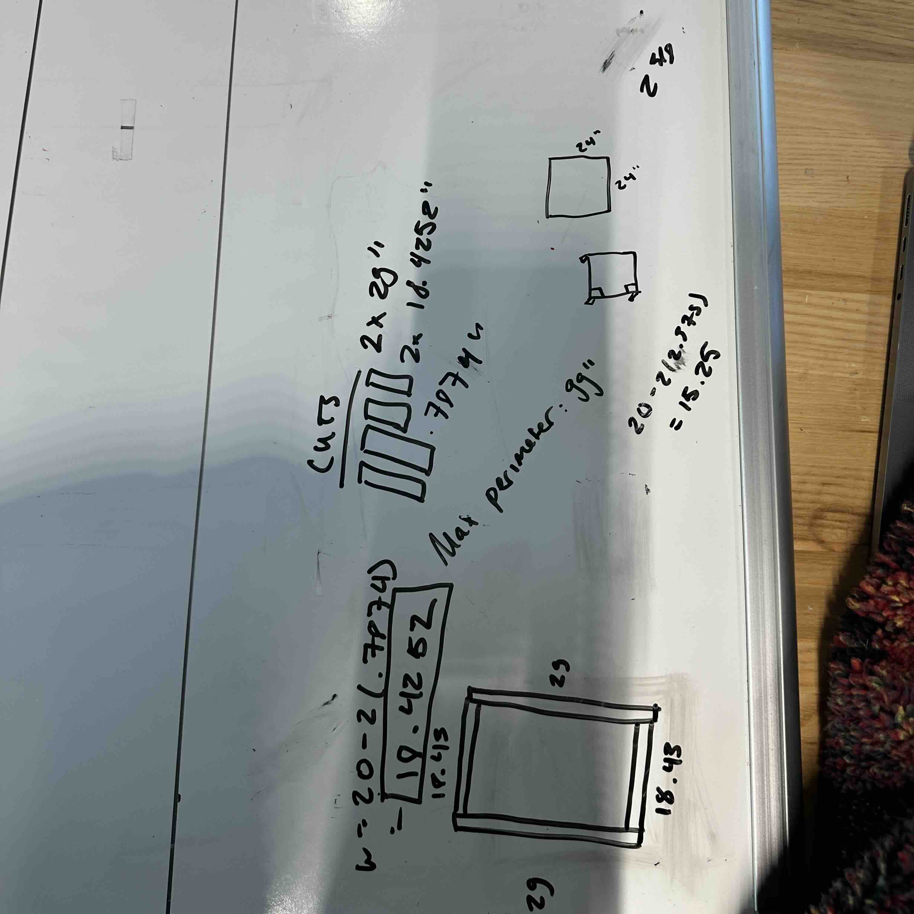
The frames were designed and the provided extrusions were cut to a dimension of around 29 inches by 18 inches with a miter saw. The cut extrusions were easily connected right after this step to form the perimeter of the frame.
Afterward, through CAD, we determined the design and sizing of motor mounts, the cart mounts, and the connections between the main frame and the extrusion that would act as the rail for the cart. Since there would need to be two belts installed overlapping one another, it was determined it would be necessary to have one motor slightly more elevated than the other. We also wanted to raise the frame slightly to give space for adjustments on the pen’s z position using foot-shaped 3D prints.
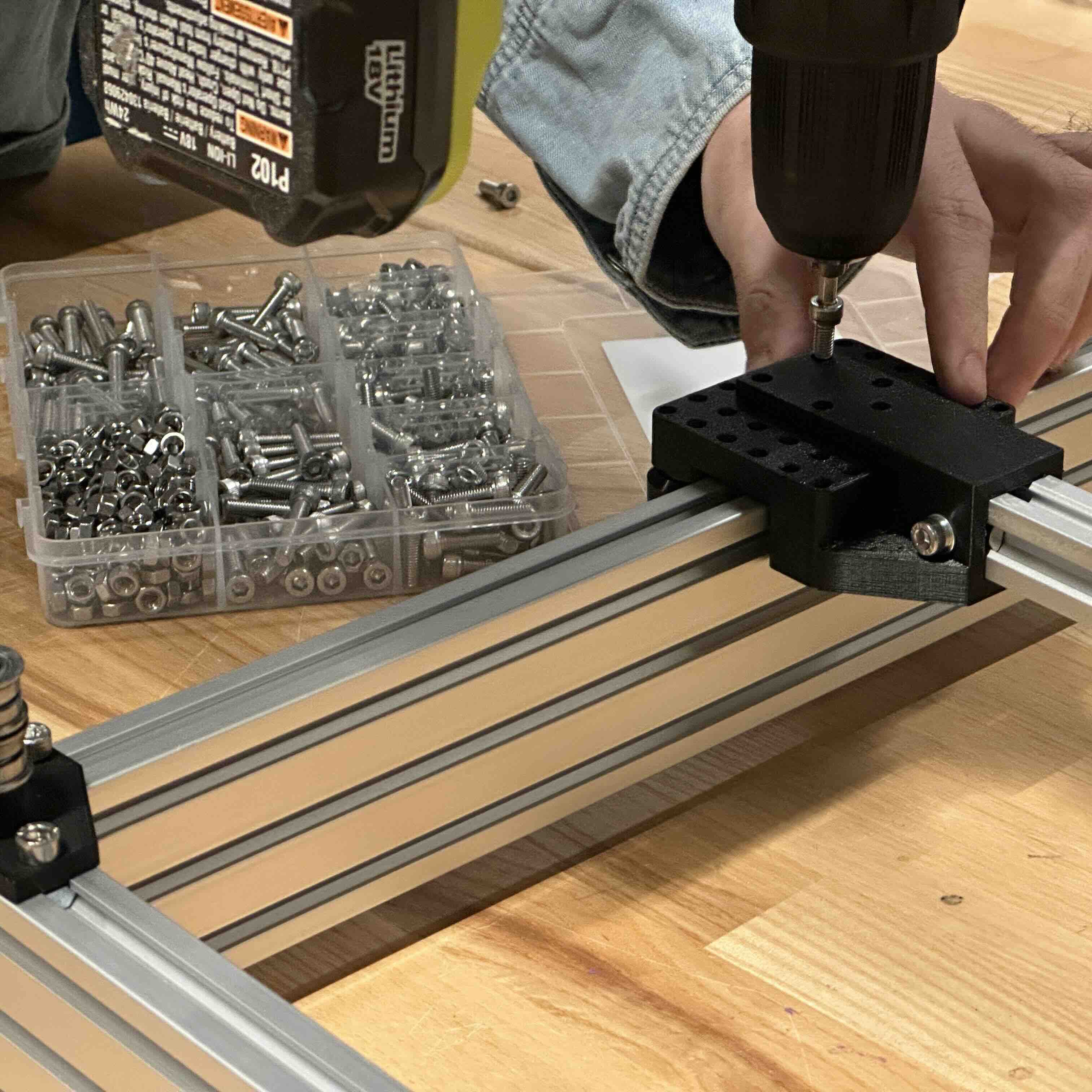
Once the 3d prints were printed, we were able to mount the motors and screw them in place at the ends of the frame and give the frame four feet to stand on. We then mounted the horizontal 2020 extrusion that would act as the rail for the cart to move on. This required 3d printed connections to mount as well as an additionally designed rail mount that would connect the belts at the right height into the cart. Once these were all screwed in quickly (shoutout to drills), we were able to install the belt. Following the CoreXY, we were able to position the belts and tighten the belts for the maximum tension using zip-ties. This was enough for us to move forward and test the movement of the XY-axis of the frame. We were able to successfully draw a small-scale rhino from the provided code.


Step-by-Step
We created a drawing robot that draws caricatures. Frame and Motor Control Team’s main goals were to build the frame, and get the motion to work at the X and Y-axis.
Frame Construction
- Design the frame: Initially planned for a large whiteboard-sized machine. Downsized to approximately 29 inches by 18 inches due to belt length constraints.
- Cut extrusions: Use a miter saw to cut the provided extrusions to the specified dimensions
- Assemble frame perimeter: Connect the cut extrusions to form the outer frame
Component Design and Printing
- Design components using CAD software: Motor mounts, Cart mounts, Connections between main frame and cart rail extrusion, Foot-shaped supports for frame elevation
- 3D print the designed components
Motor and Frame Assembly
- Mount motors: Position one motor slightly higher than the other to accommodate overlapping belts. Secure motors to the frame ends using screws.
- 3D print the designed components
Cart Rail Installation
- Mount horizontal 2020 extrusion: Use 3D printed connections to attach the extrusion to the main frame. Install the specially designed rail mount to connect belts at the correct height for the cart.
- Secure components: Use a drill to quickly fasten all parts in place.
Belt Installation
- Install belts following the CoreXY configuration: Position belts according to the CoreXY layout. Use zip-ties to tension the belts, aiming for maximum tension.
Testing and Validation
- Test XY-axis movement: Verify smooth motion of the cart along both axes.
- Perform drawing test: Successfully draw a small-scale rhino using the provided code.