HAOHENG TANG'S PROJECT
HTMAA23
Week 9: Input Devices
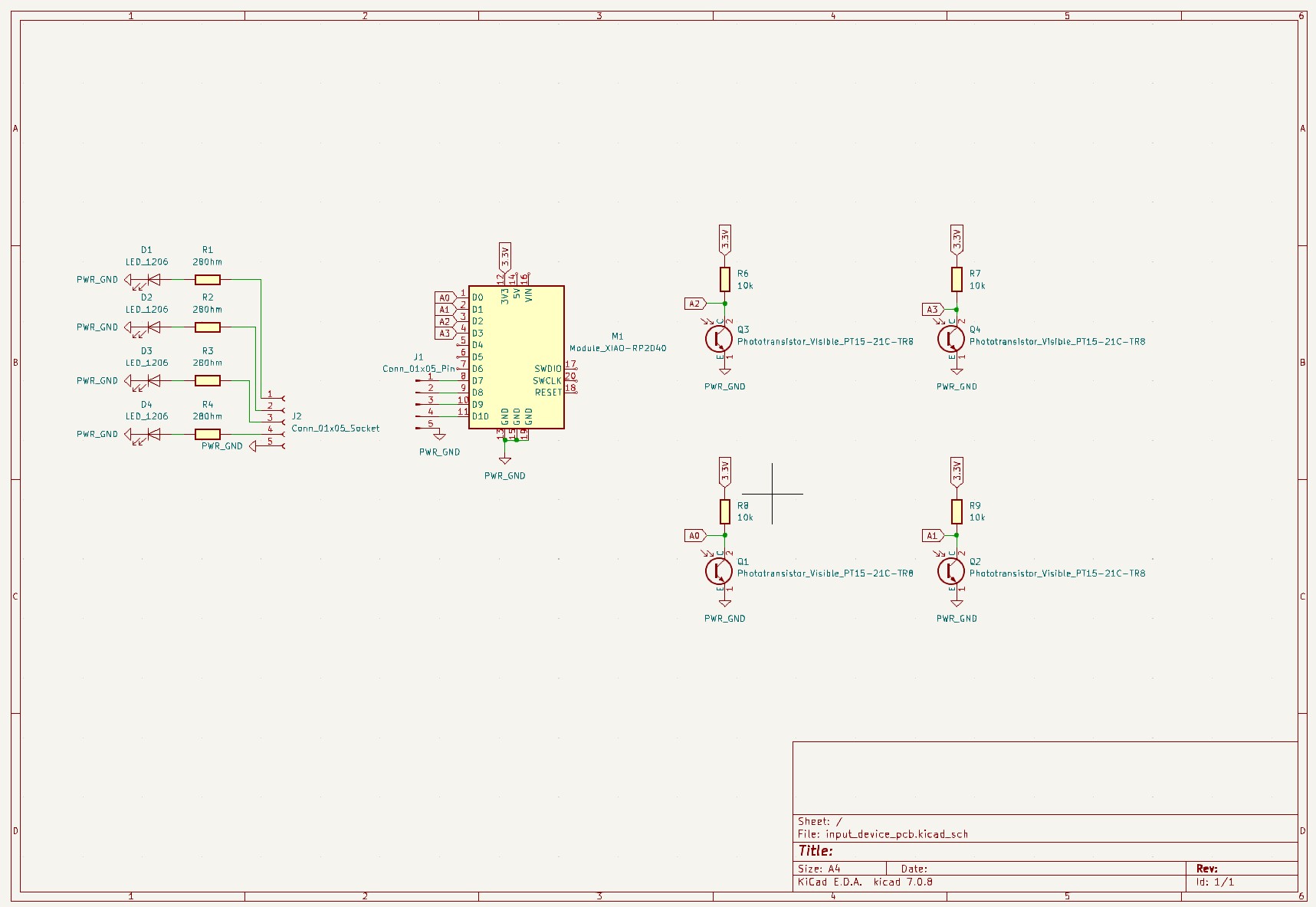
Ideas & Design
I'd like to use pairs of phototransistor and LED to test something and measure the rate of oscillation.
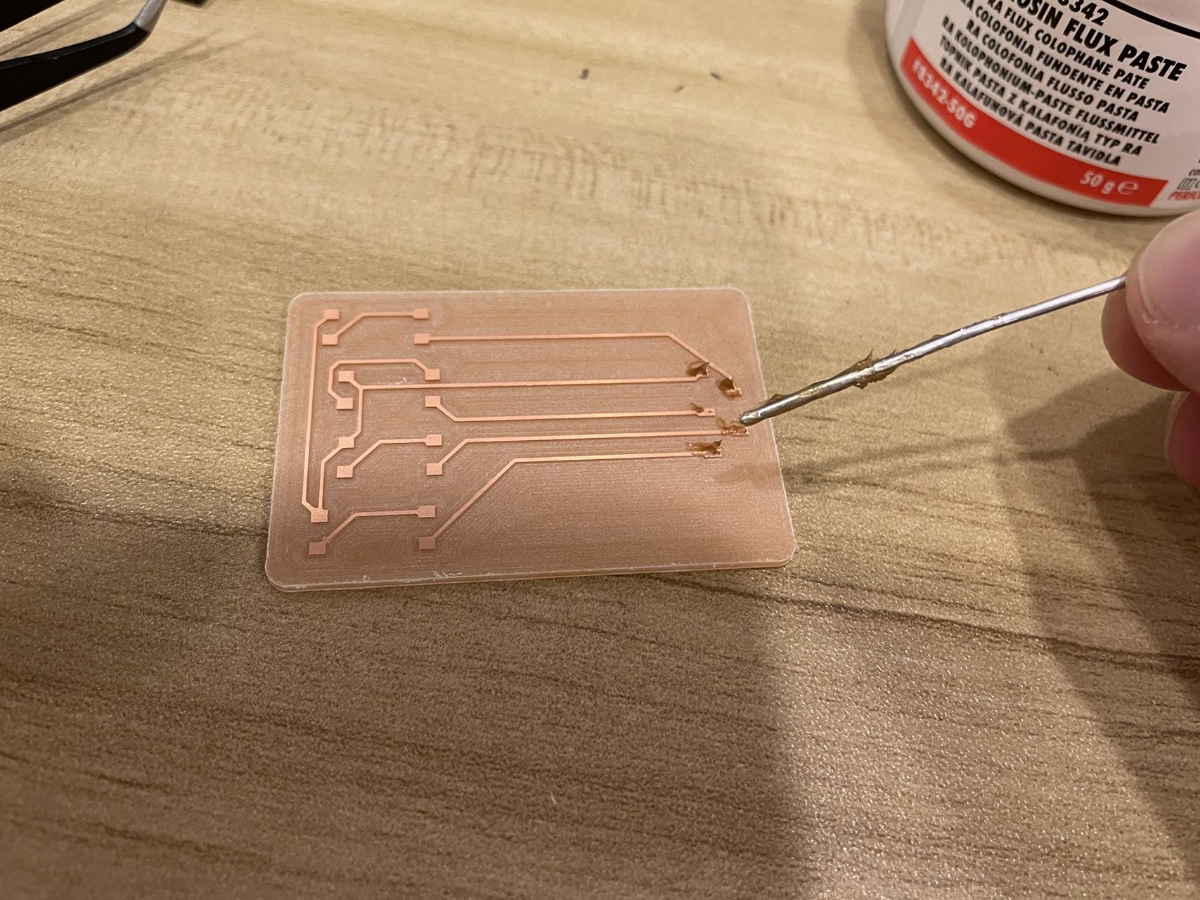
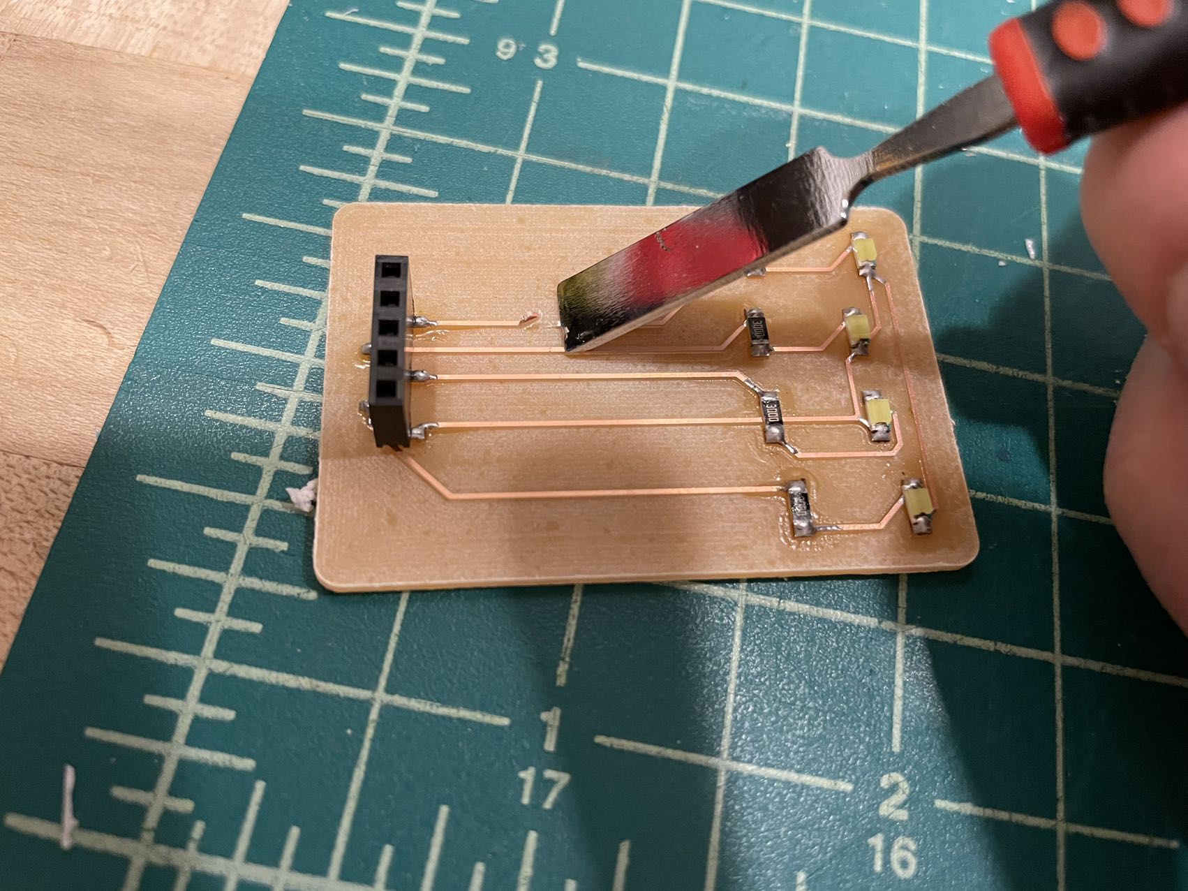
PCB Milling
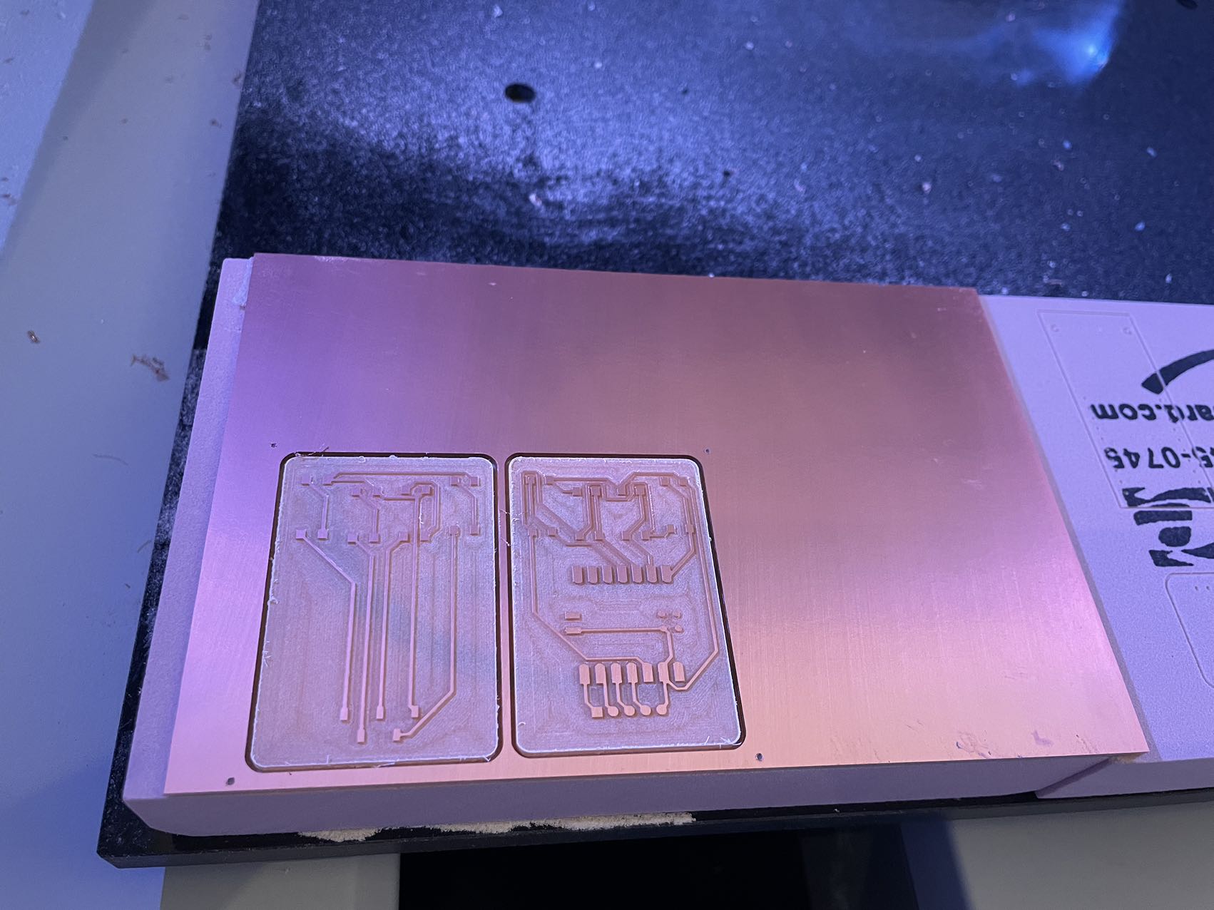

The CNC process went well! Thank you Lindong for you G-Code!
Also thank you to my best friend Quincy for providing CNC machine!
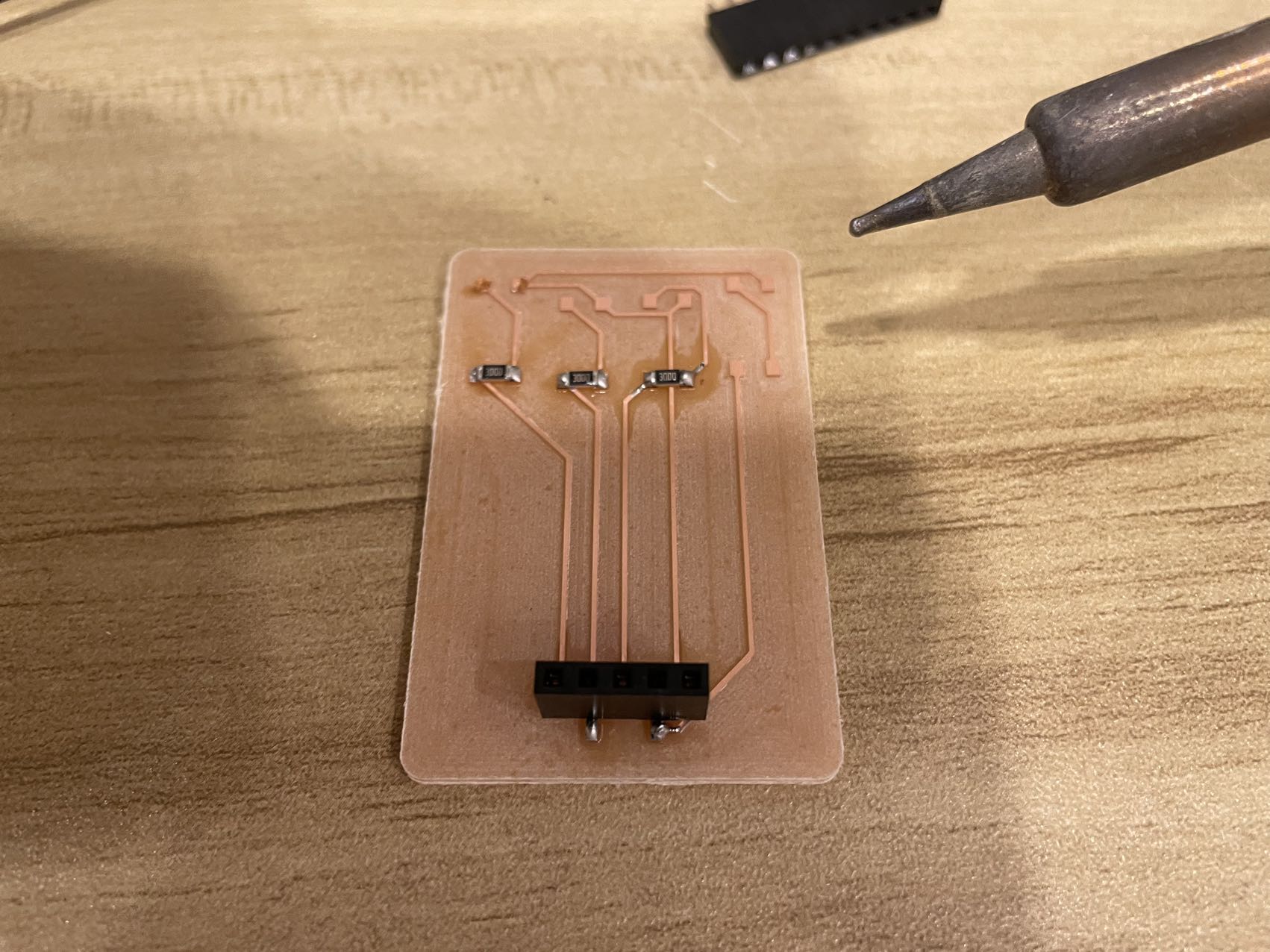
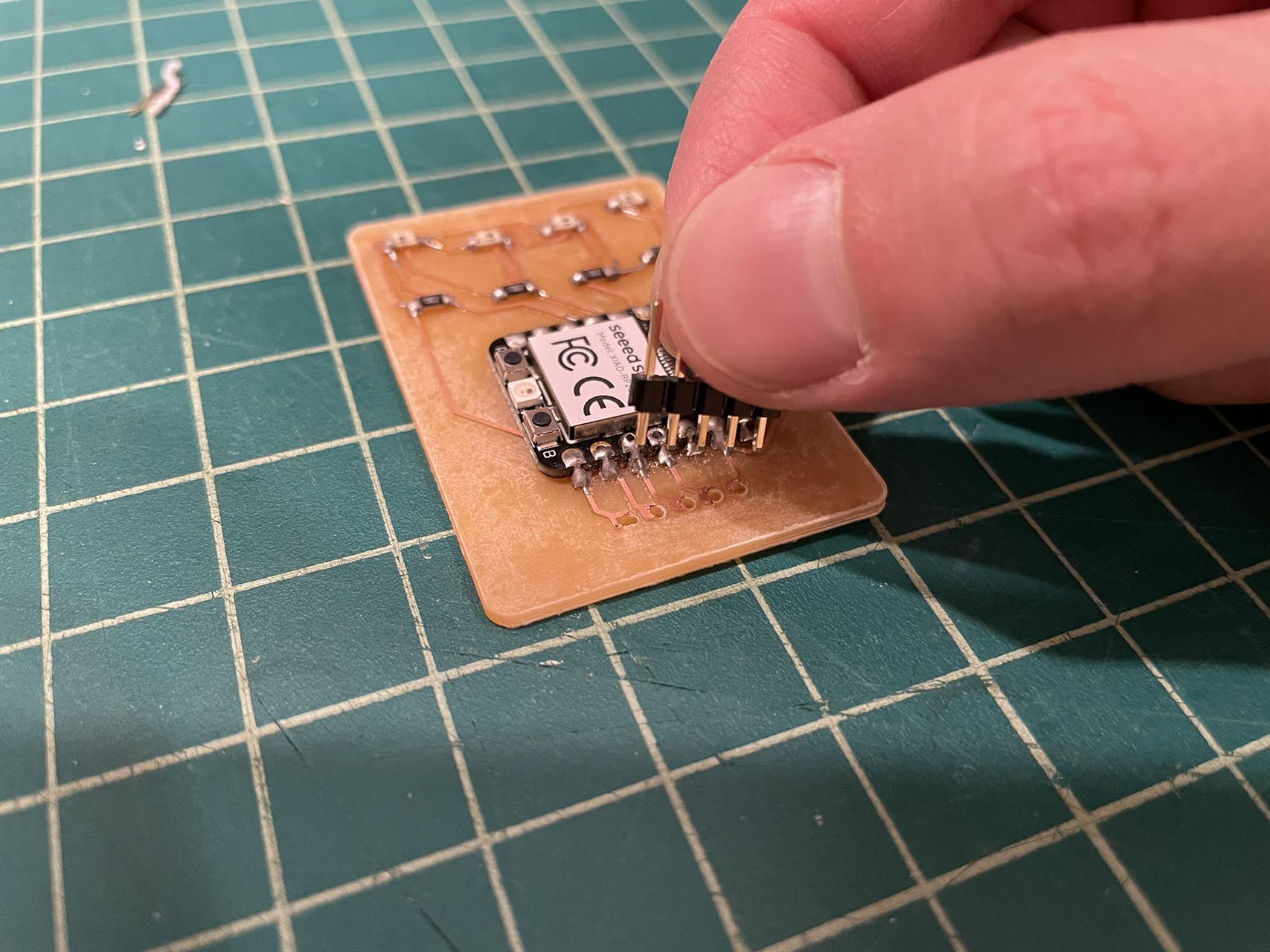
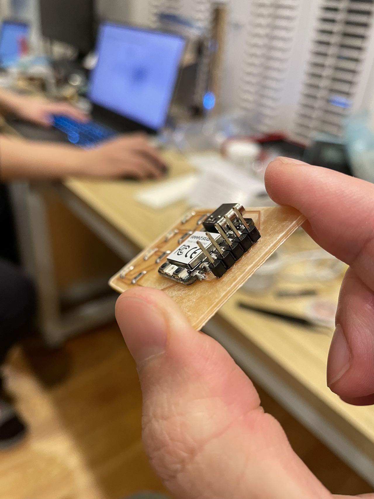
Soldering
BUG1
Unfortunately, I forgot to drill holes on the pins during the CNC machine so I decided to drill them manually.
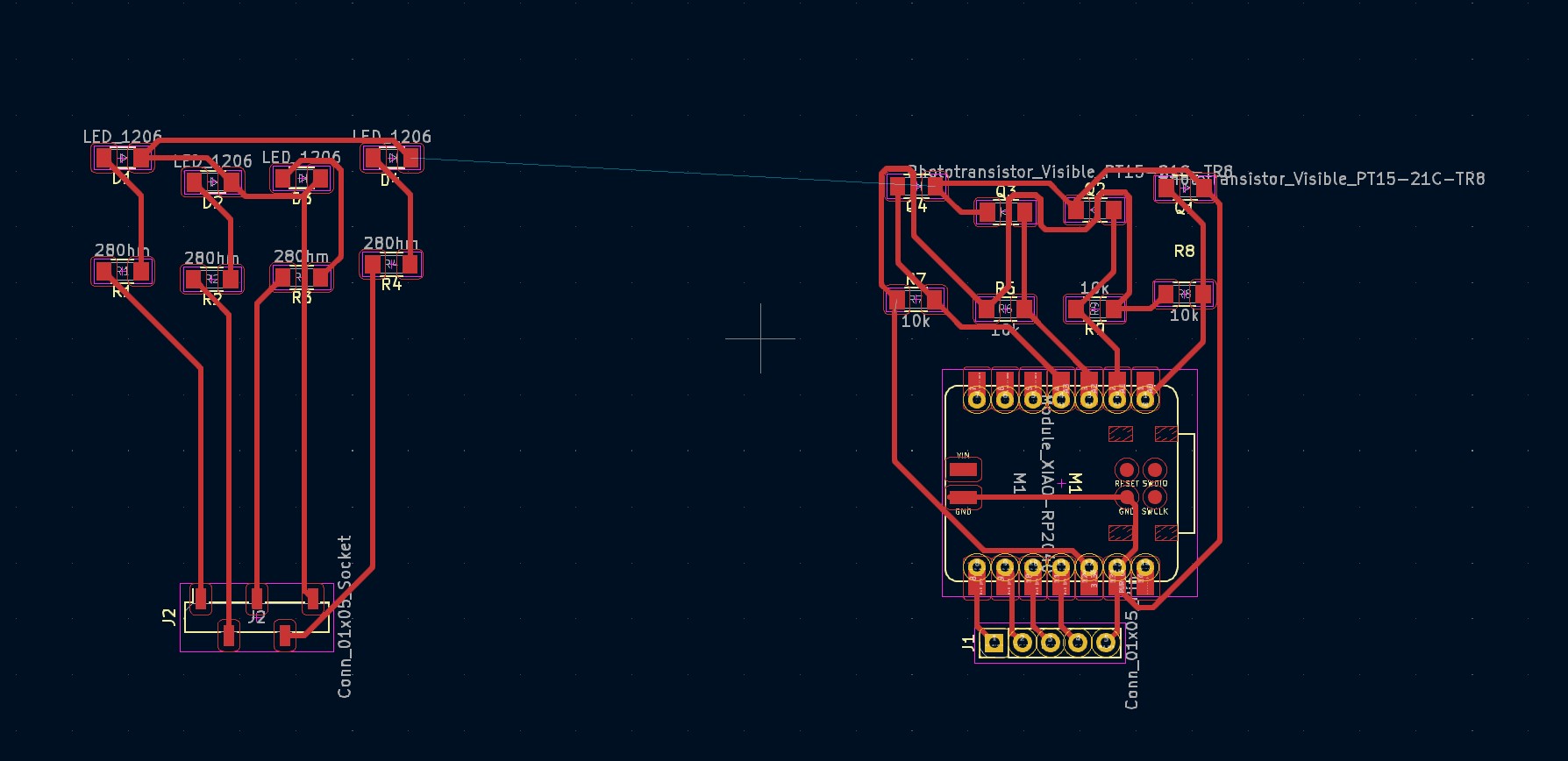
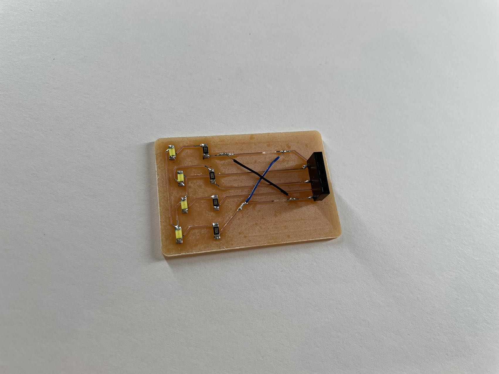
BUG2
Since my two PCB will be placed in a "face-to-face" way, I should have mirrored one of them, but I forgot to do so...
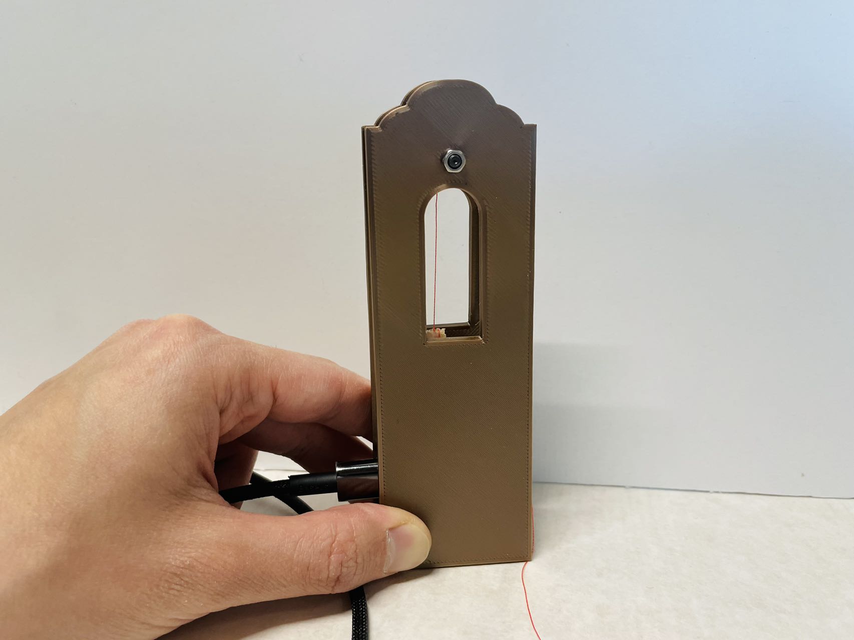
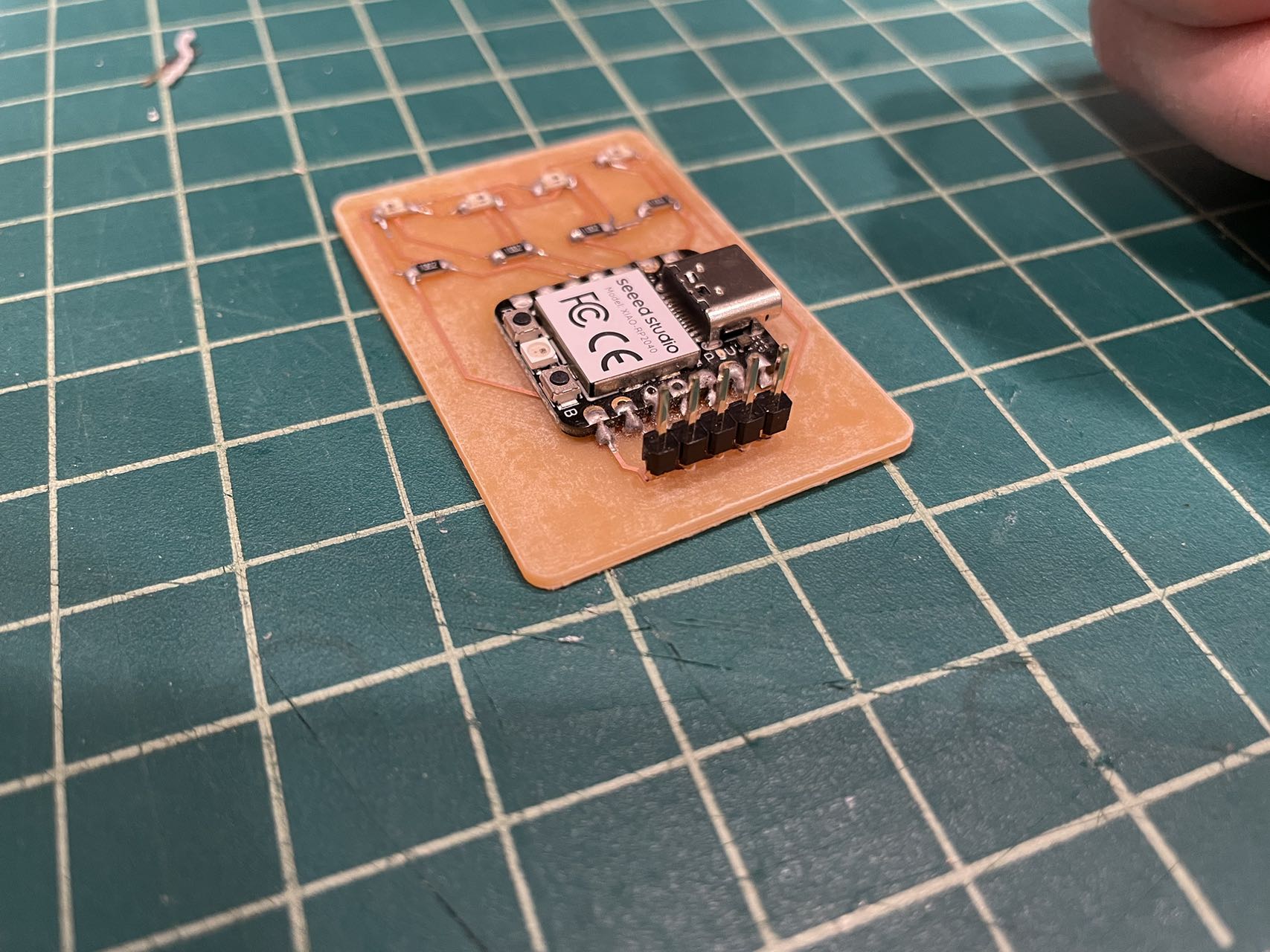
Final Prodcut
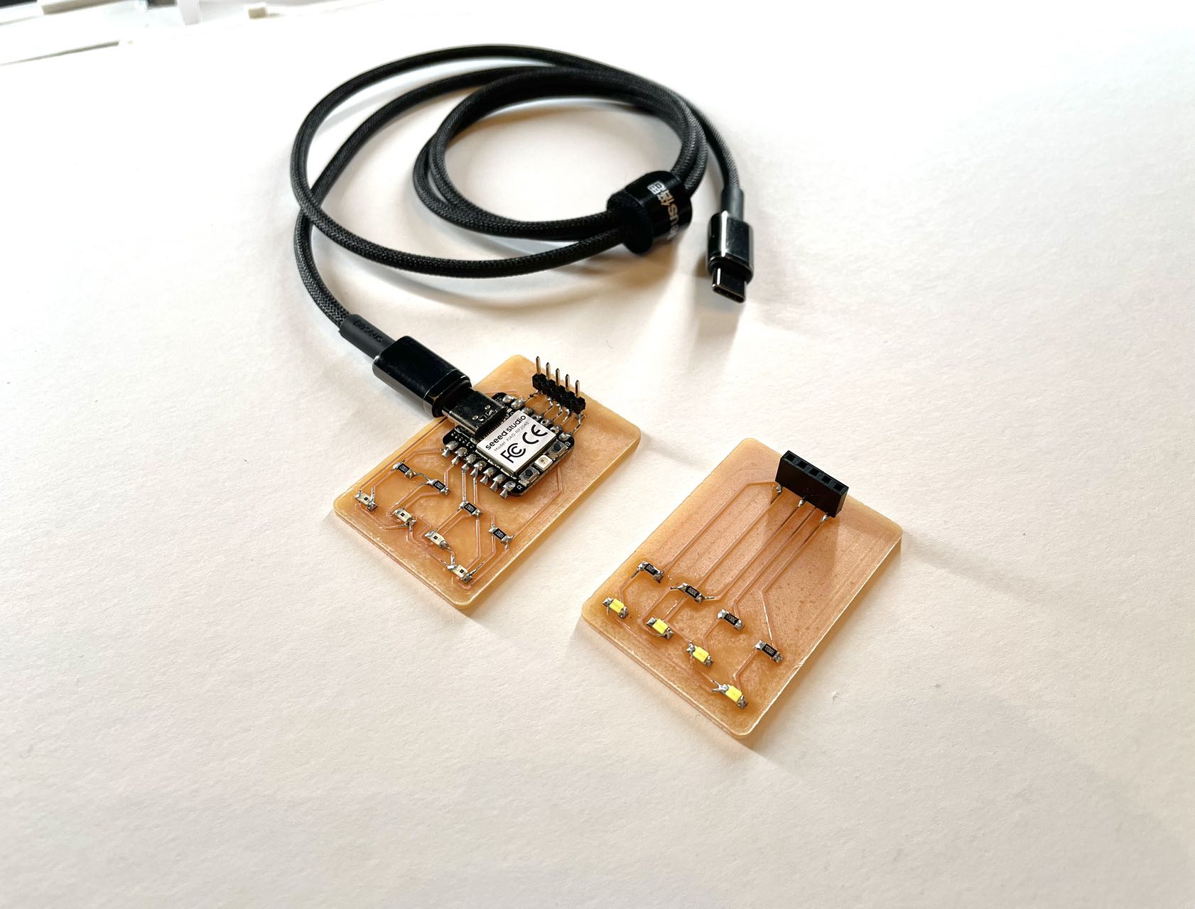
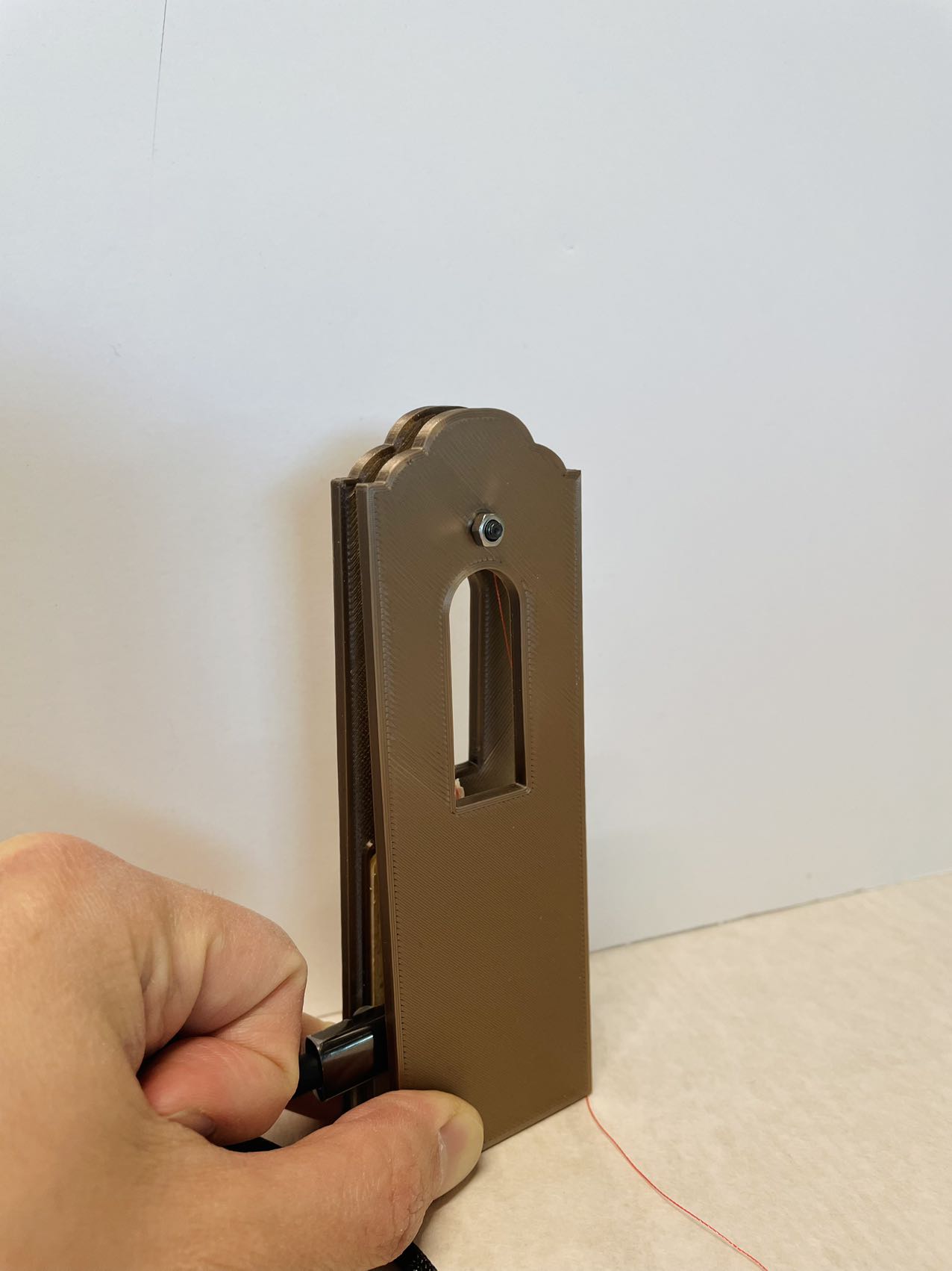
Input test
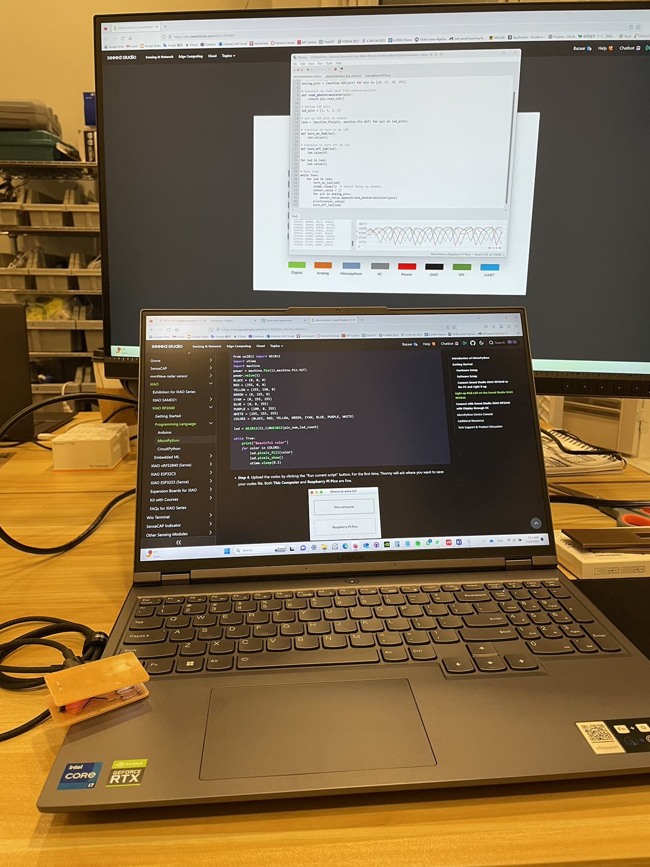
My first test proved that the phototransistors on the device is able to capture the change of the pattern of the LEDs on the other side.
The other test showed that the device is able to sense the rate of the osscillation inside, which moves like a pendulum.