Julia Benevides

Computer Controlled Cutting

So, I had many attempts for the lasercutting assignment for this week. Changing my idea or realizing that I used the wrong program for the assignment.
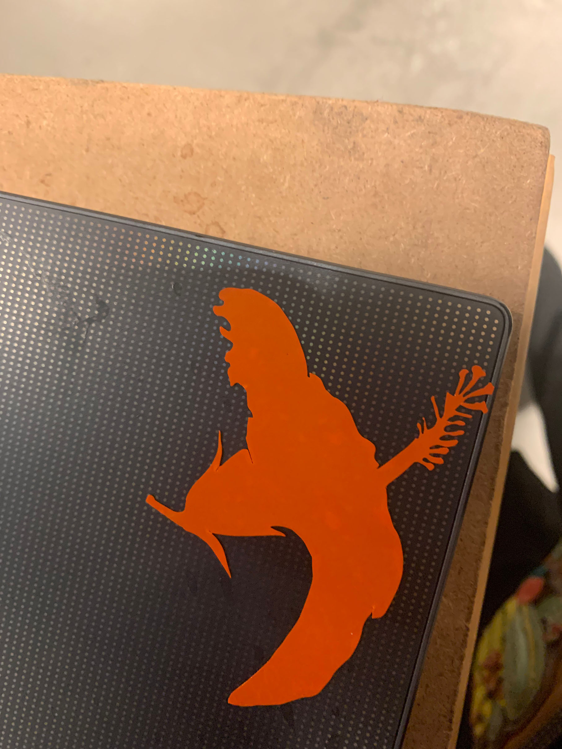
Attempt 1 The Bugs

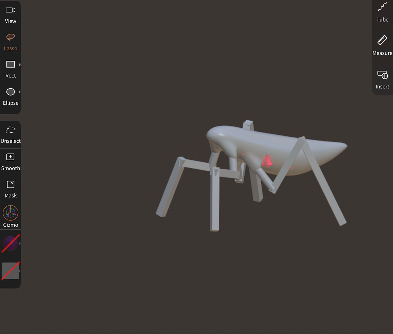
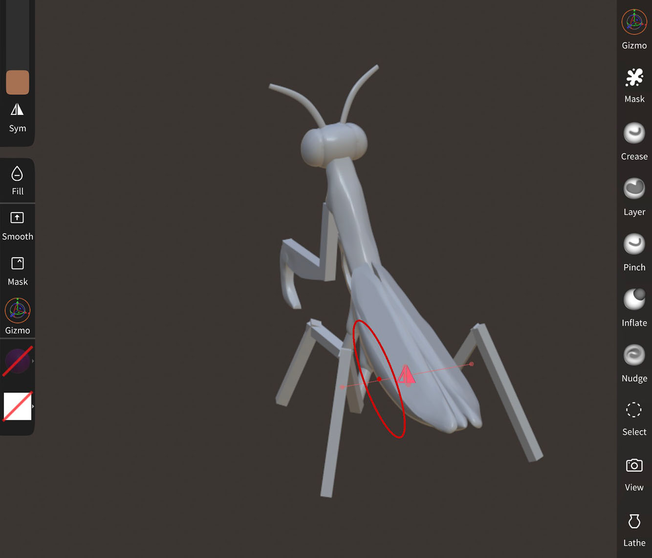
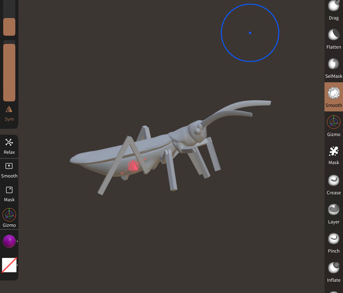
My first idea was to model in Nomad a praying mantis and a grasshopper, since their anatomy is surprisingly similar. I tried to make very simple bodies and shapes in order to make it easy to recreate with flat objects. I had tried to bring it into Fusion 360’s slicer but each time it ended up crashing so I was unable to.

Beginnings of the Mantis Model Finished Mantis Finished Grasshopper in Nomad

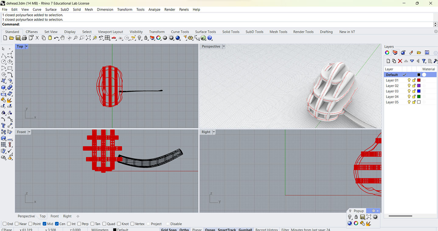
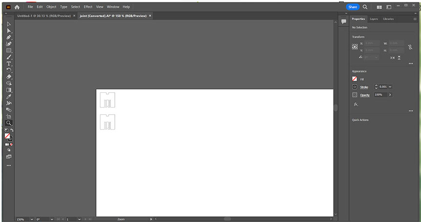
So instead I brought the models into Rhino and used the contour tool to get the general shapes of the creatures layers. With selecting two angles that are perpendicular to each other, I then used planarsrf on each curve in order to make a surface.

Contouring in Rhino

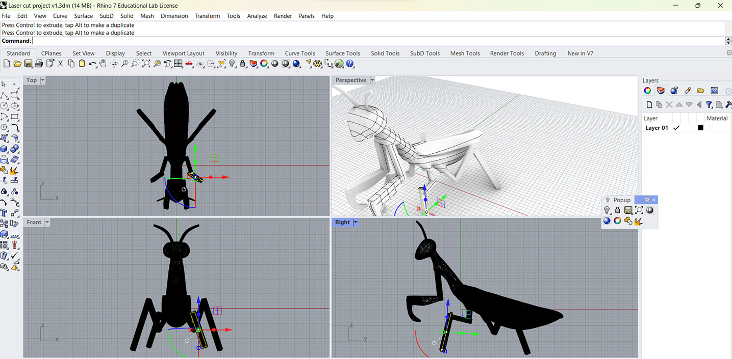
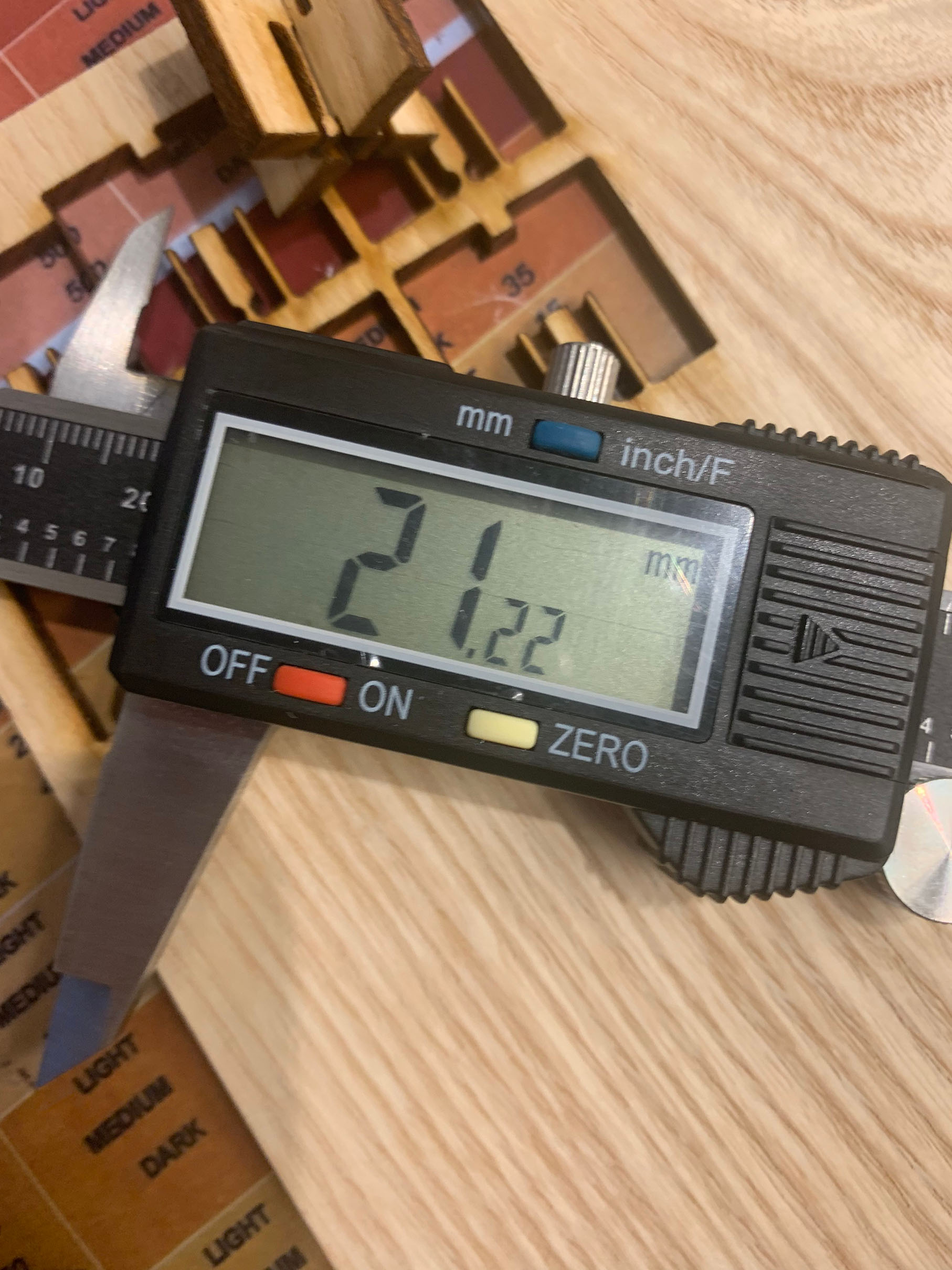
To make it an object with thickness I had to use the ExtrudeSrf tool. Making the thickness be the same as the material I was using, I made it 1/8in thick.

Extruded

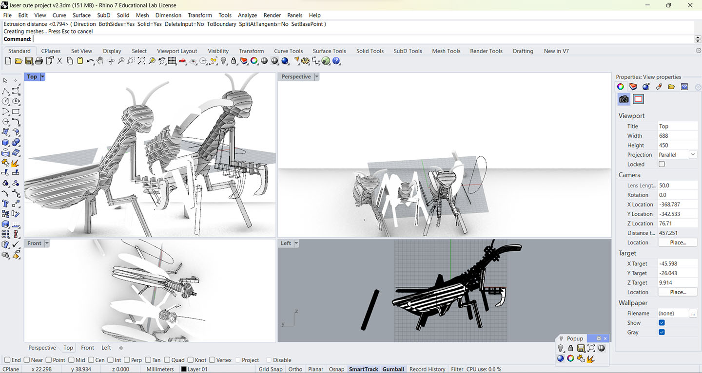
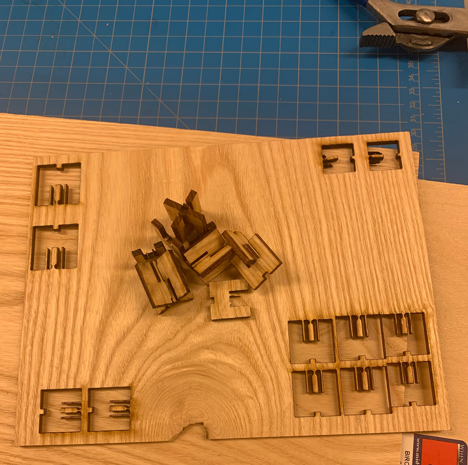
After doing the mantis model and most of the grasshopper model, I moved just the mantis head to another file in order to work on it separately. Then, the first thing I do is use the Orient3pt command to get the flattest point of the head to lay flat on the x axis. Then, using a flat rectangular surface to split each layer in half (This is in order to cut out pieces only to the halfway point since each piece needs to have half of its length in order to lock into place). Using the intersecting pieces I then made duplications of the pieces I wanted to cut away from certain layers, and would do that with each piece but alternating each side I would do it on. It was at this point that I realized this could actually work, but I would run out of time before I could finish it. So I had to come up with a new idea. (also had forgotten about it having to be parametric and this would not have worked for that requirement)

Oriented and Sliced

Attempt 2 The Lanterns

So my next idea was to make little lanterns made of the mystery wood in order to make a shape that can continue to connect to itself in multiple different ways.

The Beginning of the Triangles

So I designed two triangles in Adobe Illustrator(This project also isn’t parametric so I have another attempt later). Making sure two sides of the larger triangle are equal being 2.65in long with the shorter side being 1.84in.Then making another triangle with all sides being 1.84in, I then created a line of 9 1/8in x 1/8in squares to go along each long side of the larger triangle but with one side which has a square closer at the top and one with one closer to the bottom in order for this same shape to be able to clip into itself without another similar triangle being made. Then with the shorter side I put only 7 1/8in squares with making sure there was a square farthest on one side and 1/8th distance without a square on the opposite end.-> Then doing the same on the smaller triangle on all three sides.

Design

After I worked and finished the design of the shape, I unioned the shapes with the wooden teeth together. After that I drew a quadrant symmetrical design on Procreate, brought it into Illustrator and used image trace in order to get the vector paths.

Triangles with Design

Erased the lower half of the drawing in order to make a triangular shape, and closed any paths that were left open. Then duplicated it into the file with the triangles and warped it to fit the different dimensions. Offsetted the rectangular outline by .11mm to make up for the amount that gets cut away by the kerf. Then to print it the line width was set to .001 with RGB 225 0 0. Then using (insert Laser Cutting transition software name that I forgot) I put in 100% power, 8% speed, and PPI 250.

Lasercut Pieces Pieces put together Shape lantern

All the pieces fit surprisingly well and really held their places because the wood seemed to be on the sappier side so it almost worked like temporary glue that can be taken apart. I could put the pieces together to make a pyramid, a diamond shape, (if there were more small triangles a deltahedron is possible), and the amount of faces can just keep increasing. But the main function was as a small lantern. The joints also work very well for staying together even when moving the other pieces. But I didn't add a video since the size would not go below 5MB.

Attempt 3 The Box

But this wasn’t parametric, so I had to attempt it again since that part had slipped my mind. So I tried fusion again.

The Beginning of the Box

I imported a box into Fusion 360’s slicer, it sliced itself into 5x5 layers, but I brought it down to 4x4.

1 of8 Pieces

Due to the fact that I struggled to import more than one of the plan pieces into the same file, I imported only one since they all seemed to be the exact same, just 4 of them were flipped horizontally. So I imported only one piece to do modifications on.

Imported lines

After sizing it up to be 5inx5in, I made the vertical center line, and the horizontal center line, then divided it up into 8 equal sections horizontally in order to delete every other line and make 4 horizontal center lines on one side.

Making the Joint

. Then make a line from the vertical centerline from the first bottom horizontal centerline down by 1/16in and draw a line from the end of that line to the right edge line.

Pattern

From there I mirrored it over the centerline and used rectangular pattern command with a distance of 95.25mm and a quantity of 4 so it can be the same as the original piece but instead have the correct dimensions.

Fillet

Then I filleted all the corners around the joints by 2.50. And did a offset of 0.11mm to account for the kerf. Then imported the dxf file into illustrator and made the power be 100%, speed 5%, and PPI 1000 for the 1/8in acrylic.

box Finished Box

Using clear and orange acrylic I cut and assembled the box. BUT, I realized I couldn’t get the change parameters to work in the end so I still don't know if this is parametric, no matter where I looked even when following tutorials I wasnt able to find the icon I needed. As well as I couldn’t constrain everything I wanted to since it was somehow over constrained already.

Vinyl Cutting

For the vinyl assignemnt I decided to draw a hibiscus flower since I have recently worked with them a lot and thought it would be nice as a sticker.

image of hibiscus

After doing a quick drawing on Procreate, I imported the lineart into Illustrator and Image traced it.

loading image into cricut software

Then imported the image into the cricuit software as a .DXF and proceeded as the instrustions said.

The cutting

Applying a small amont of red/orange vinyl in the top left corner of the sticky mat I inserted it under the cricut blade and proceeded to cut it.

Sticker on my Laptop

After taking it off the mat and cutting the excess off, I used the transfer tape and removed it from the backing, and applied it onto my laptop. But I did have problems with getting each piece off of the tape.

Kerf Test

For testing how much offset I would need I ended up using a 1/8in thick random wood I found as my material.

The illustrator file

Using the fissure joint example given in the Joint file by Neil Gershenfeld.

The Kerf

I was able to determine that with using the settings with vector cutting with the power 100%, Speed 8.0%, and PPI 250, that with both the width and height of the square being 21.481mm, after being cut on the laser both sides had come out to around 21.22mm. So in turn I had offset the lines by 0.11mm.

The Joint test

And these were the tests I did with the joints to make sure the kerf allowed them to fit right.