Embedded Programming
Coding and anythign with electronics is very much not something I know about. So I planned to try and do the simplest programming I could.
The Code
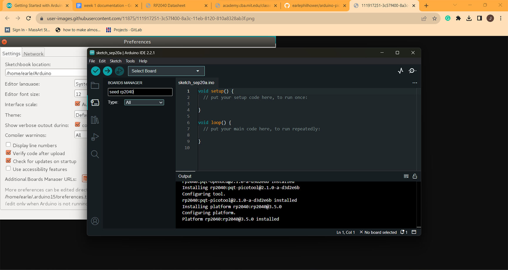
After receiving the Xiao-rp2040 and reading/scanning the manual for it. I plugged the chip into my laptop and downloaded Arduino, following along with a tutorial from TA Claire, I downloaded the Raspberry Pi Pico Arduino core, for all RP2040 boards posted by earlephilhower.
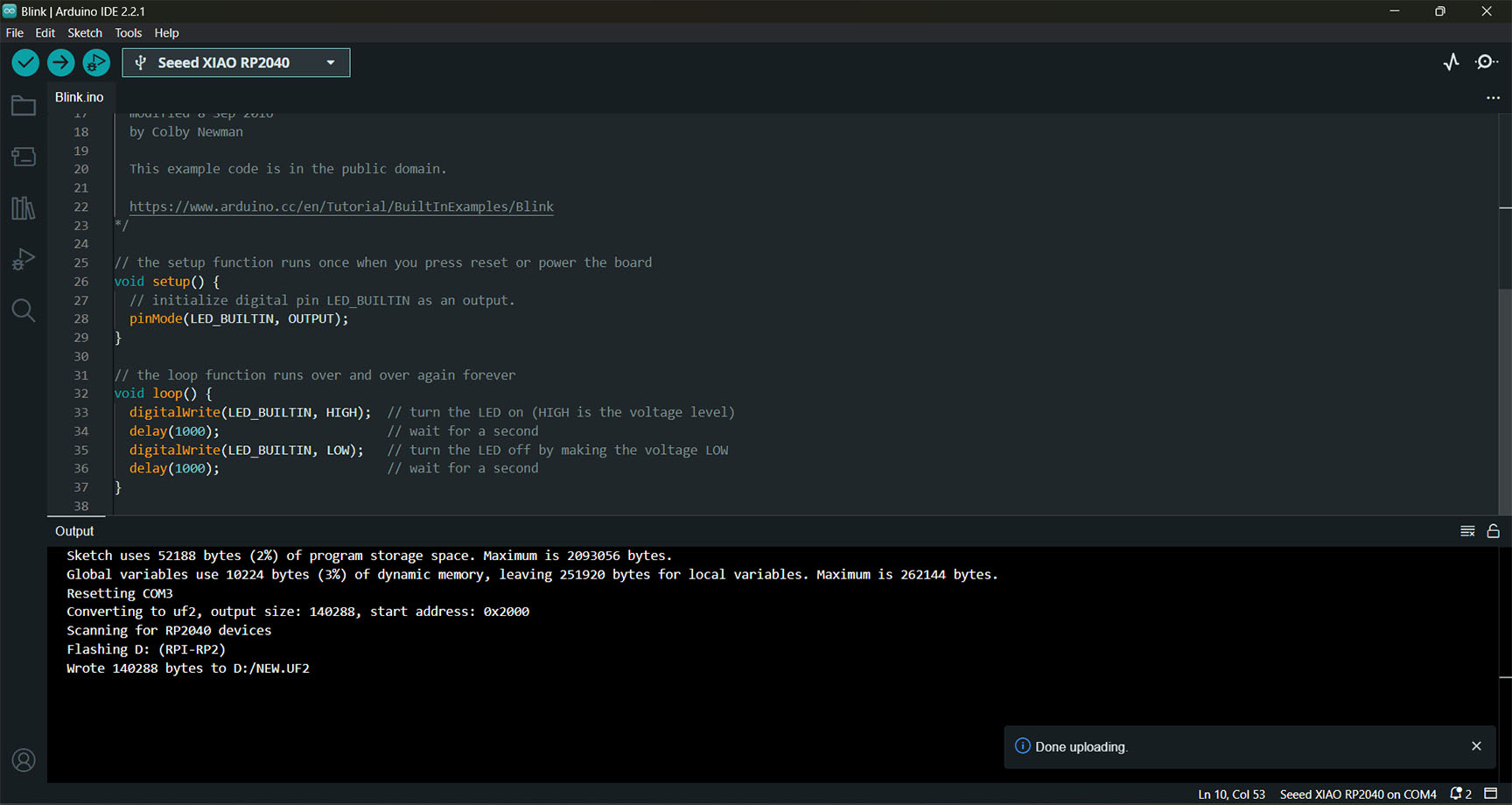
Then using Blinking example code as a base for me to try to make a add-on button initiate the built in LED to blink. But because I don't understand code very well I thought to go find other pieces of code that I would need in another code.
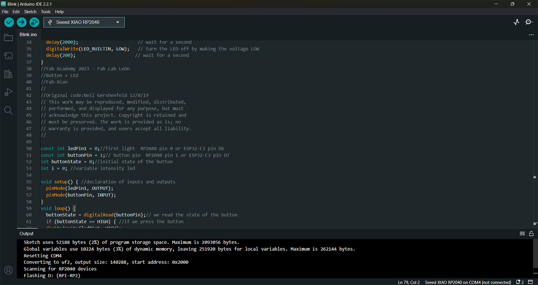
While looking at the Fab Academy Fab Xiao, I came across the Button+LED code created by Neil Gershenfeld, which seemed like it had code I could use such as the Const's and int's as well code for the button and its state. So I moved over the code that seemed useful into the Blink example code.
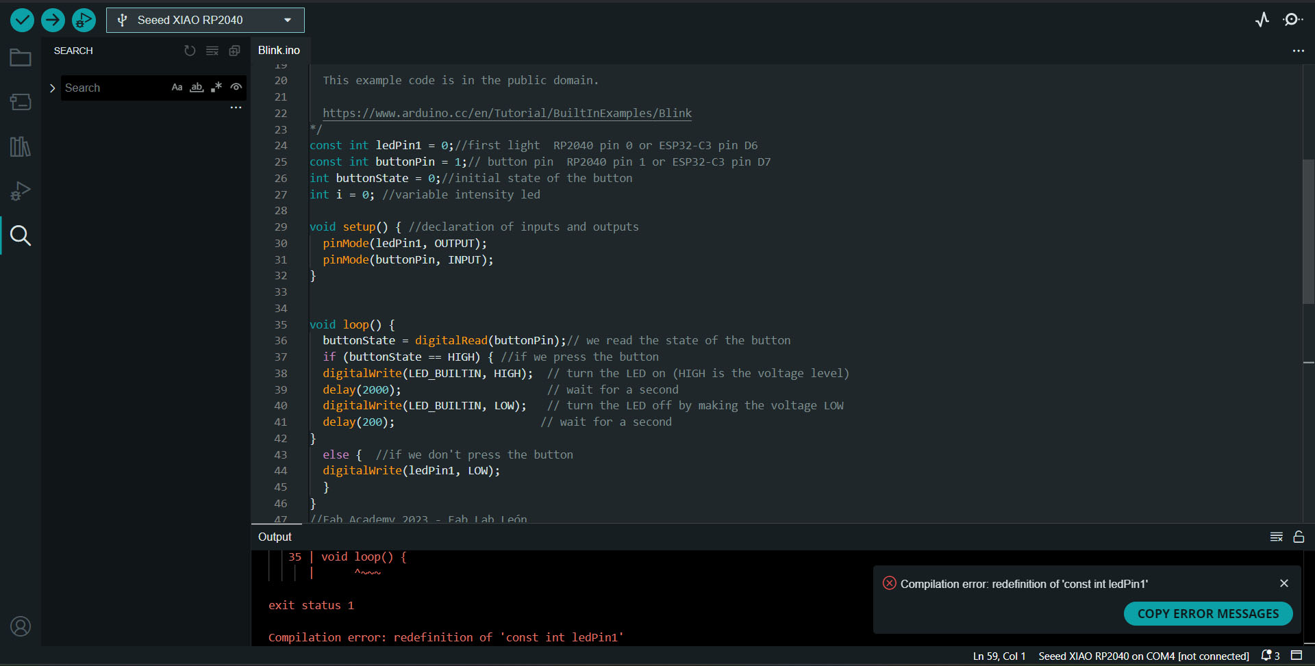
But when I put all the code together I didn't understand that const's or int's really meant, and there were alot of errors, mainly about how I redefined everything since there was also the code I copied from right below it with the same const's, int's, and different void setups and loops. So with the help of TA Quentin, he taught me what it meant and what I needed to fix. I was actually surprised that for the most part what I put in was right, just needed to be cleaned up.
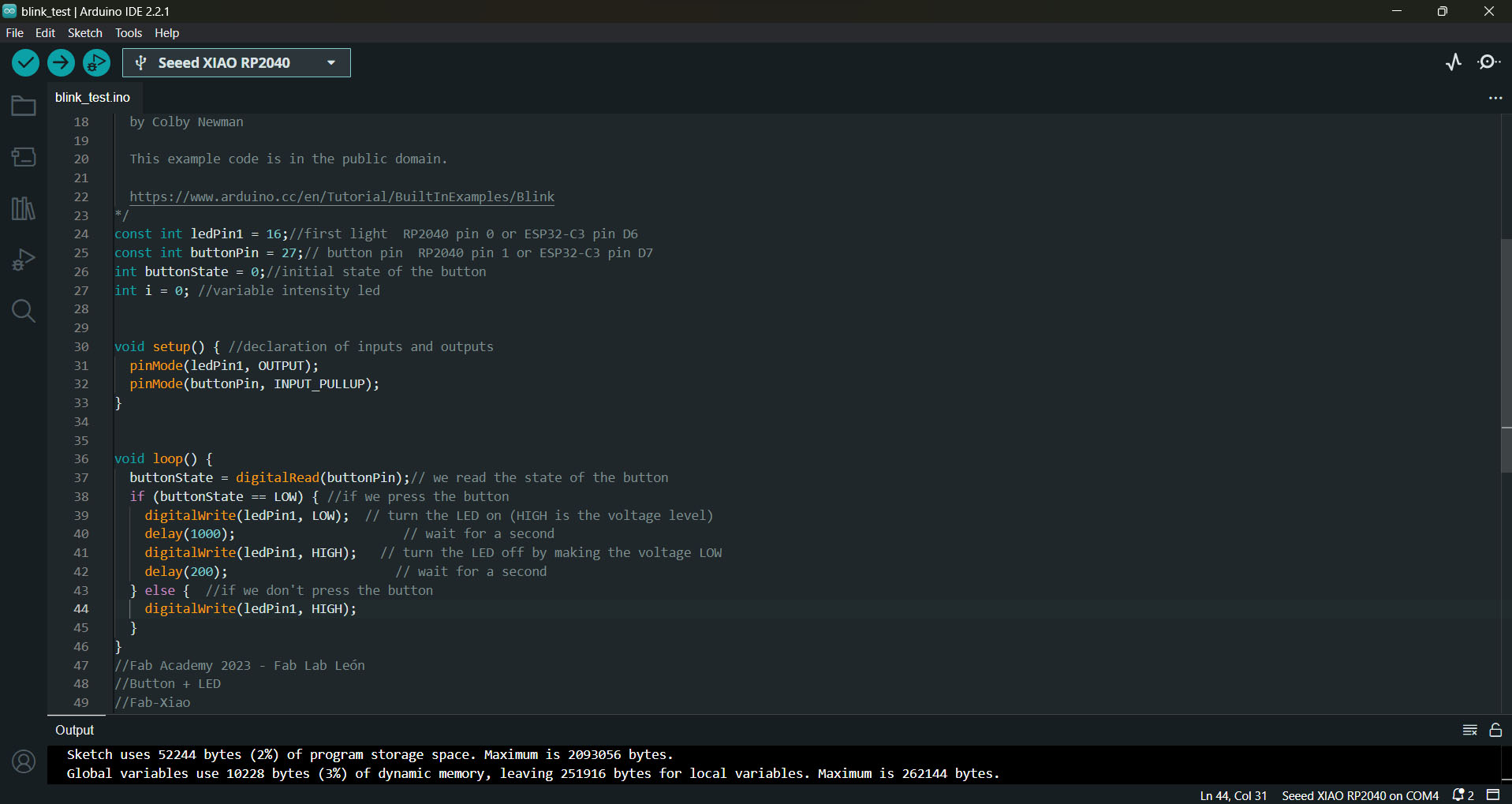
Then I just had to change the pin numbers within Ledpin1 to 16 so it was programmed for the right pin, and put the buttonpin to 27 for the same reason. As well as change INPUT in buttonpin to INPUT_PULLUP becuse the blinking was occurring when I wasn't pressing the button. So all the HIGH's and LOW's had to be switched.
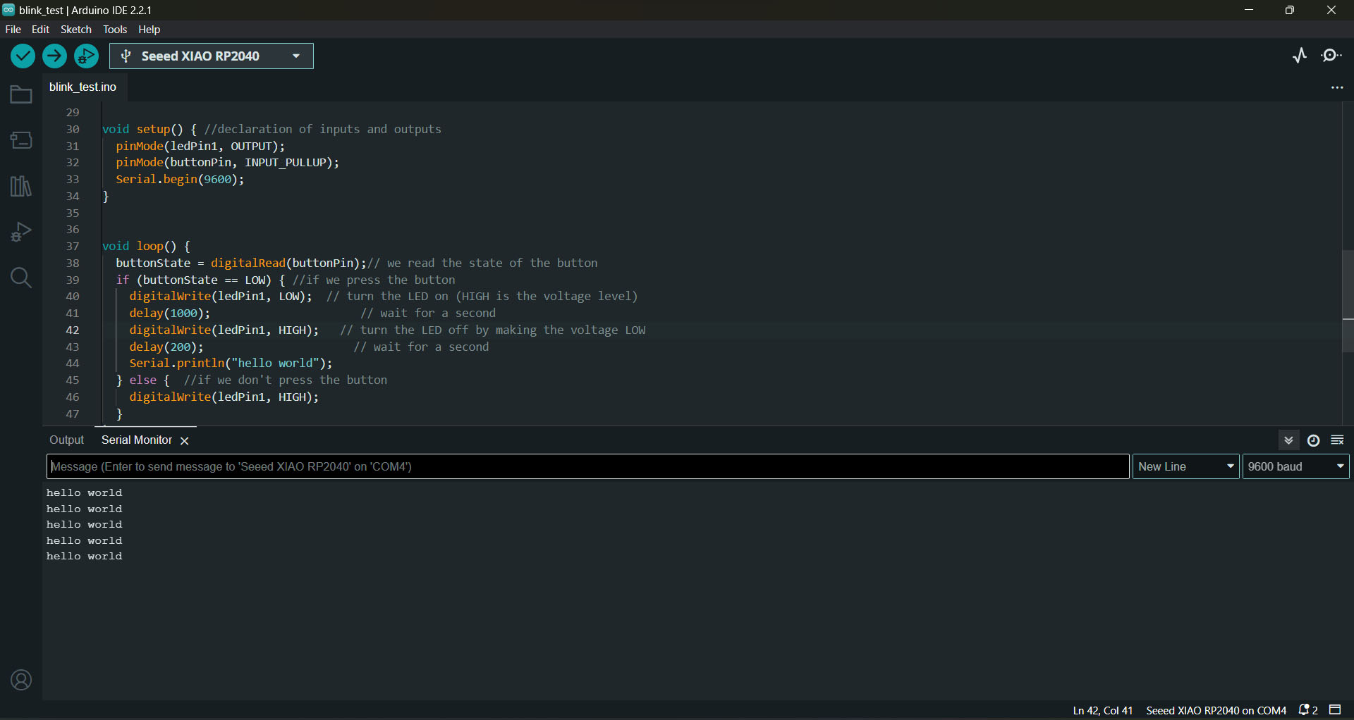
Also with the help of Quentin, going into the example code, communication>ASCII Table, found the code serial.begin and serial.println which would allow for me to get the chip to communicate "hello world" when I pressed the button.
The Wiring
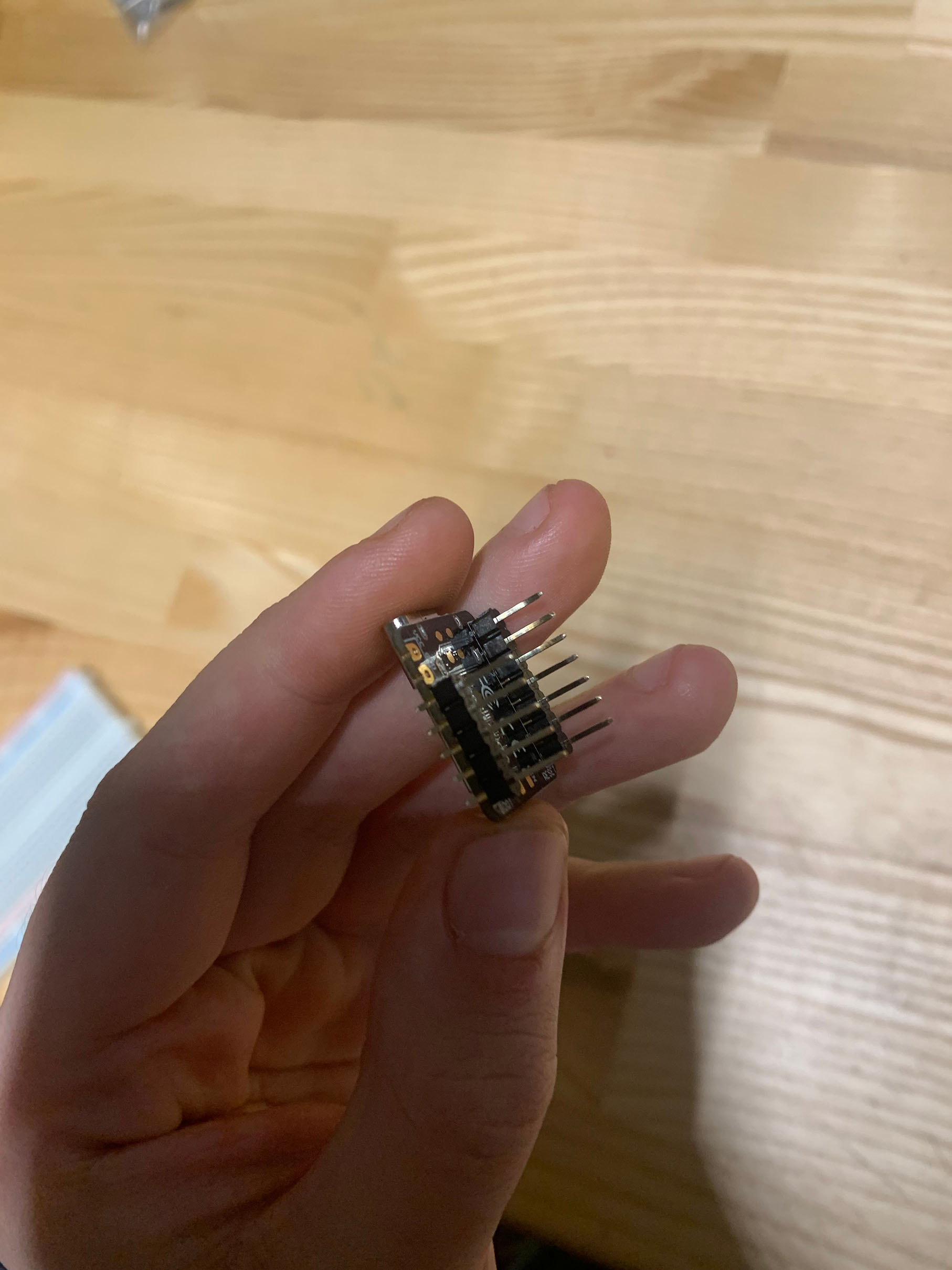
With help and guidance from the TA’s in the Harvard lab I got started with adding the pins all along the sides and soldering them in, but due to a misunderstanding on my part I ended up soldering close the grounding pin area and the VCC.
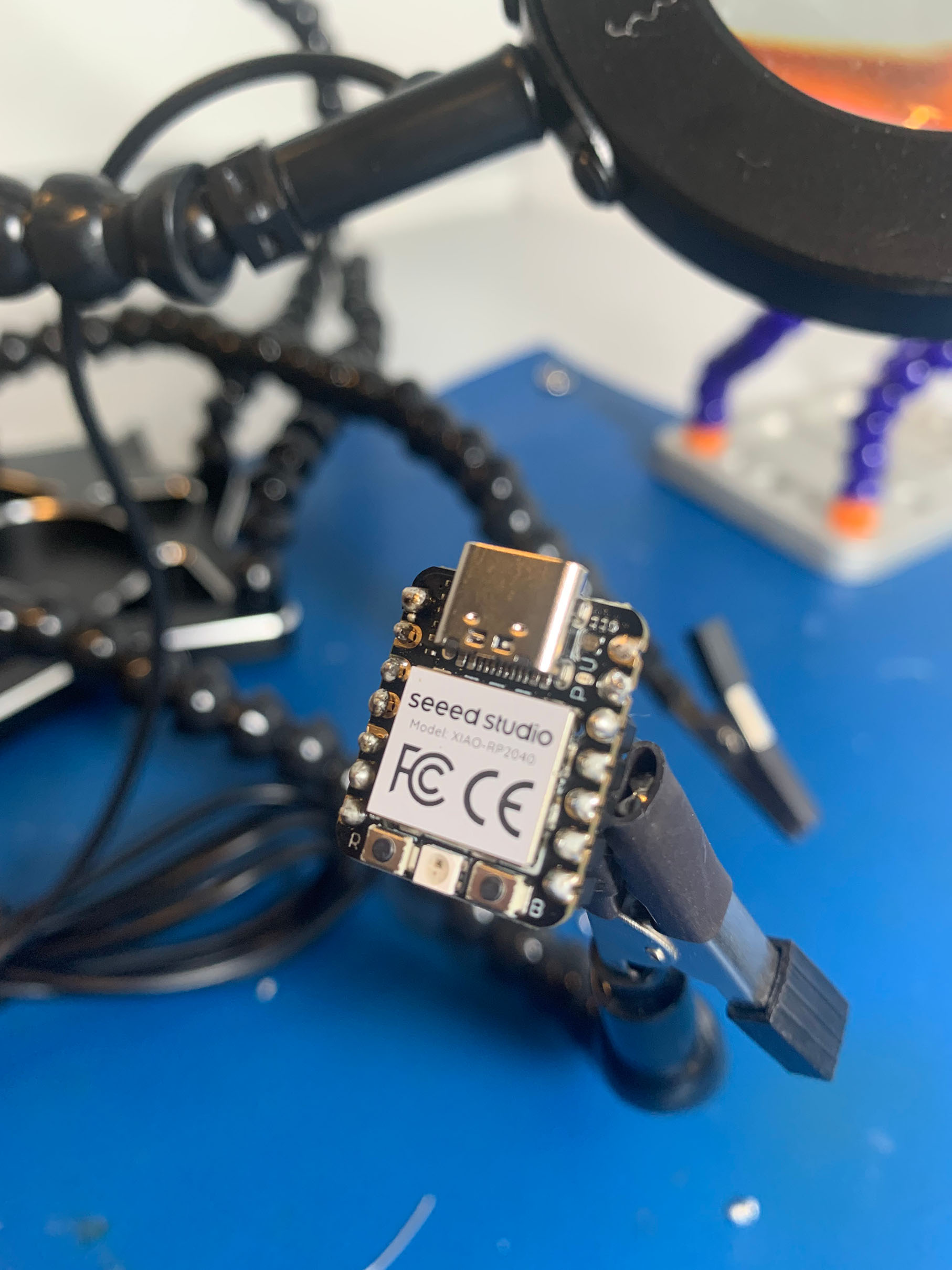
With help from TA Leo and Claire we were able to salvage and get the pins in to those areas as well.
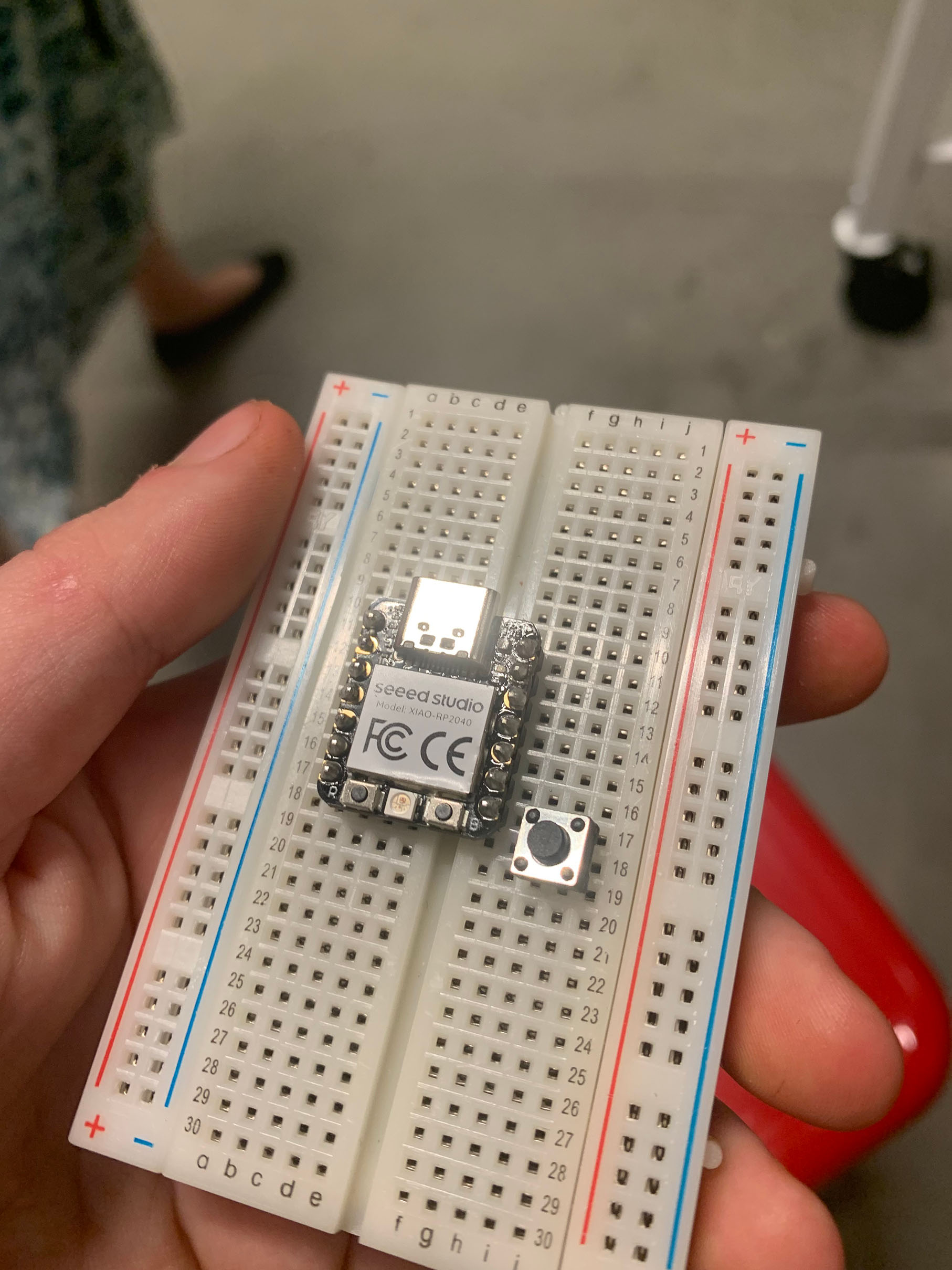
I then put the microcontroller onto a breadboard given to me along with a button in order to use it as an input device.
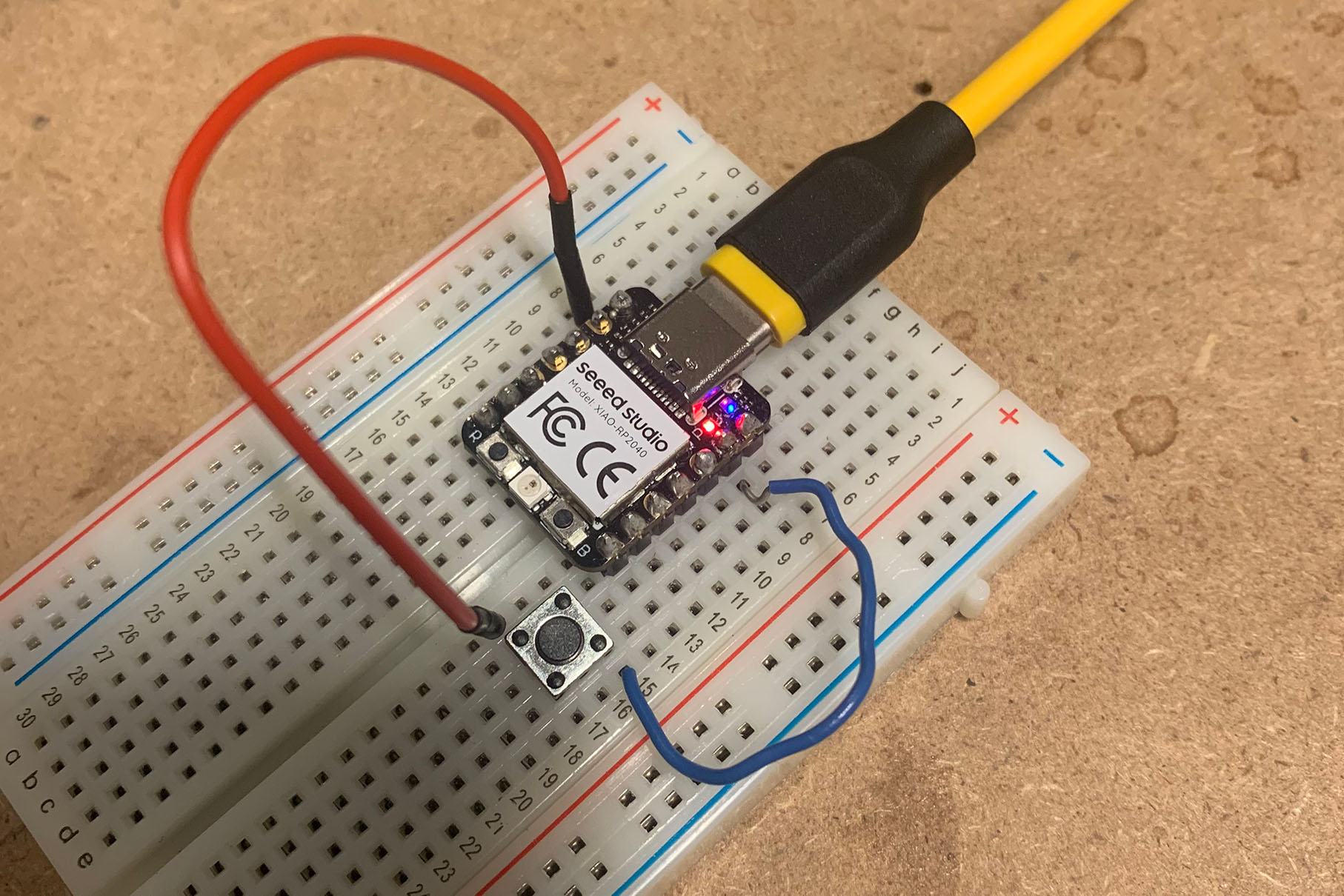
I then with two wires, I put one end into a node to the right of the grounding pin and the other end into a node to the right of one of the metal pieces in the button. Then with the second wire put one end into a node to the left of the other metal piece on the button and the other into the node to the left of the pin numbered 1 on the back of the micro controller. And thats what I did for the wiring and used my laptop as a power supply.