Electronics Production
Now that I have made my circuit design, the next step is to mill it and programming. Spoiler: Milling was a struggle. With the help of my wonderful TA Claire, we were working on milling this until 11pm since I was going away from Friday-Sunday for my birthday. So Claire was a lifesaver for staying so late to help me with it all.
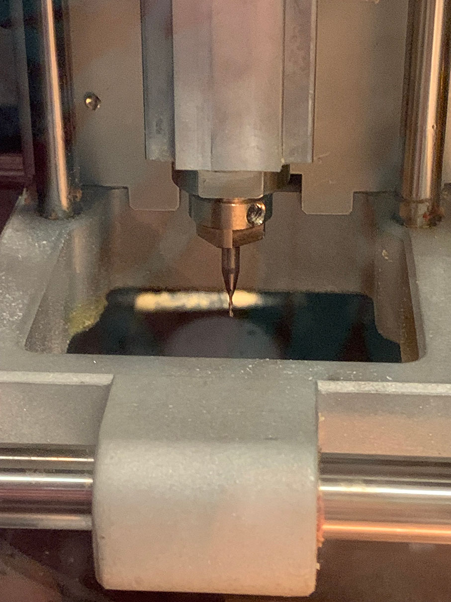
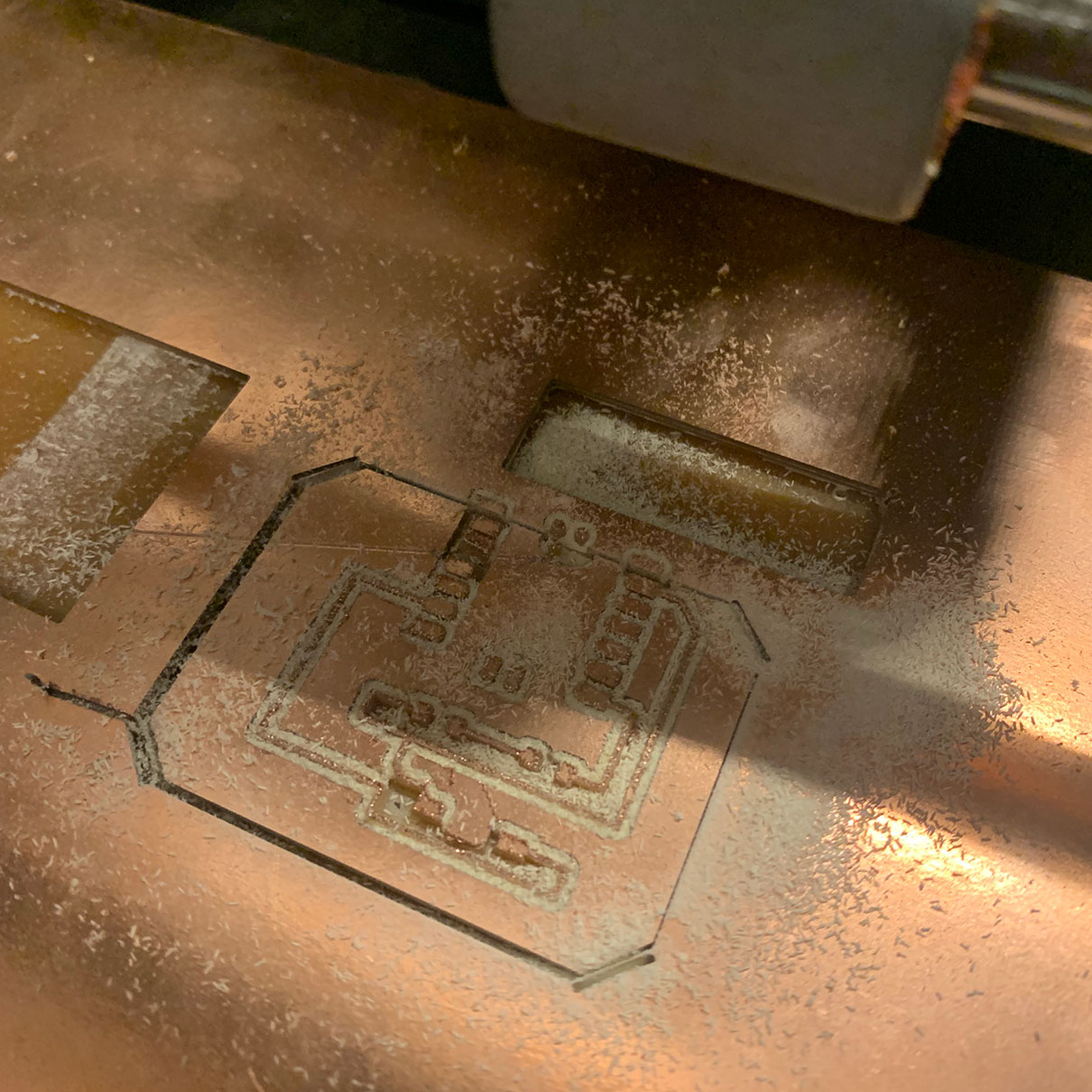
So the first thing I had to do was add the 1/32 bit to the mill head in order to etch out the details. Then as I tried to move the origin Claire and I noticed it wasn't moving and got confused only to realize it was not paired together.
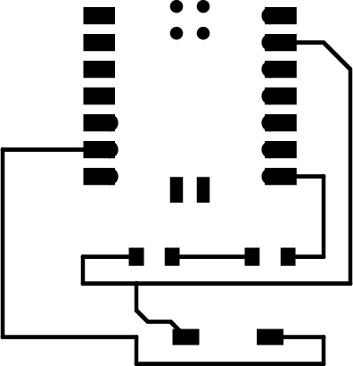

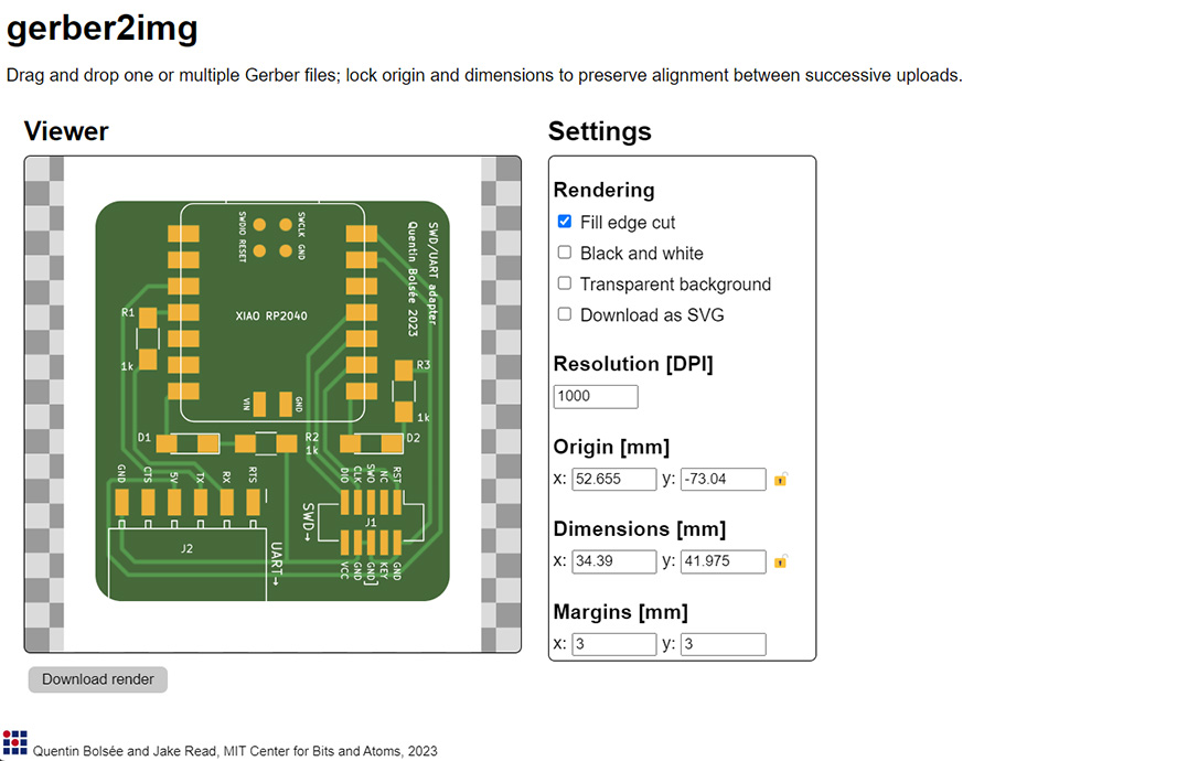
I tried using a SVG file for both the cutting lines layer and the surface etching later, but the path finding never looked right. So the first thing I tried was to convert it into a PNG, I did that using Adobe Illustrator, but it wasn't inverted and had a transparent background so it didn't work in the pathfinder, and when I finally got it to be a png the right way, the etching layer was not proportioned right to fit into the cutting layer. The next thing we tried was Quentin's Gerber converter which worked well once we figured out how to lock the dimensions so when we add in the etching layer it fits correctly.
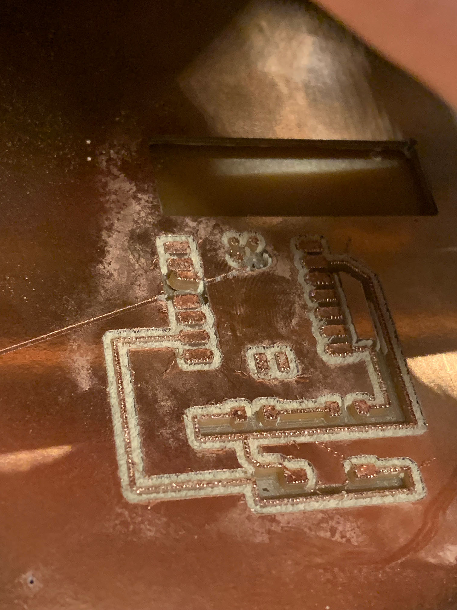
Now we could focus on making the machine work. We ended up changing the origin in order to make it etch on a specific area so we don't put in a new copper board yet. We ended up having problems on where the etching was placed on the board, but it was because we changed the home too, when we shouldn't have. But once we got that sorted out it started to etch, but it was etching rather deep for reasons we still aren't sure of.
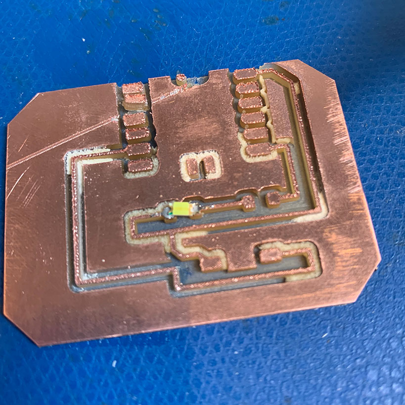
After the etching was done I switched the bit to 1/16 for cutting around the outside shape. Making sure to change the settings to mill outline. All in all the etching and cutting were a bit messed up, and there were some parts that were cut off with the outline cut, but thankfully nothing that was important to my design. Then after cleaning off the board with high grit sandpaper and a vacuum, I went to get the parts, which were the Xiao RP2040, LED 1206, Resistor 1001, and a Switch Tactile CnK.
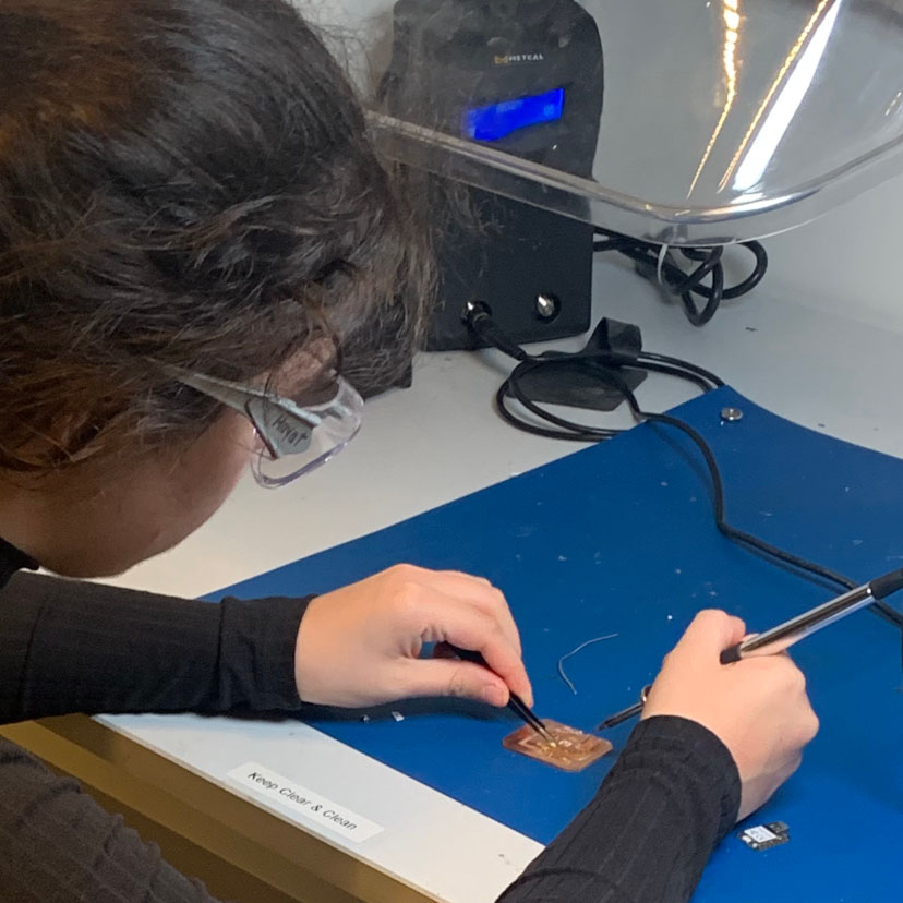
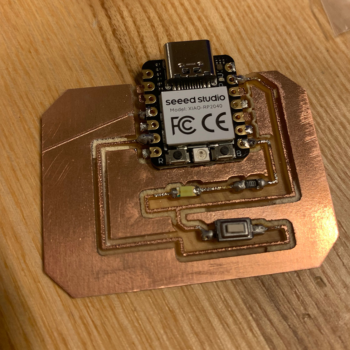
Then I soldered the components on by order of, the LED, Resistor, Button, then the Xiao.
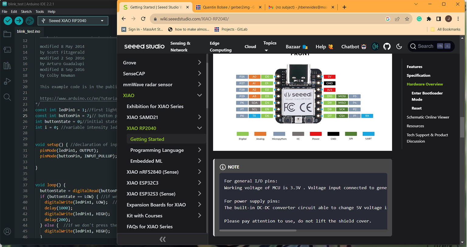
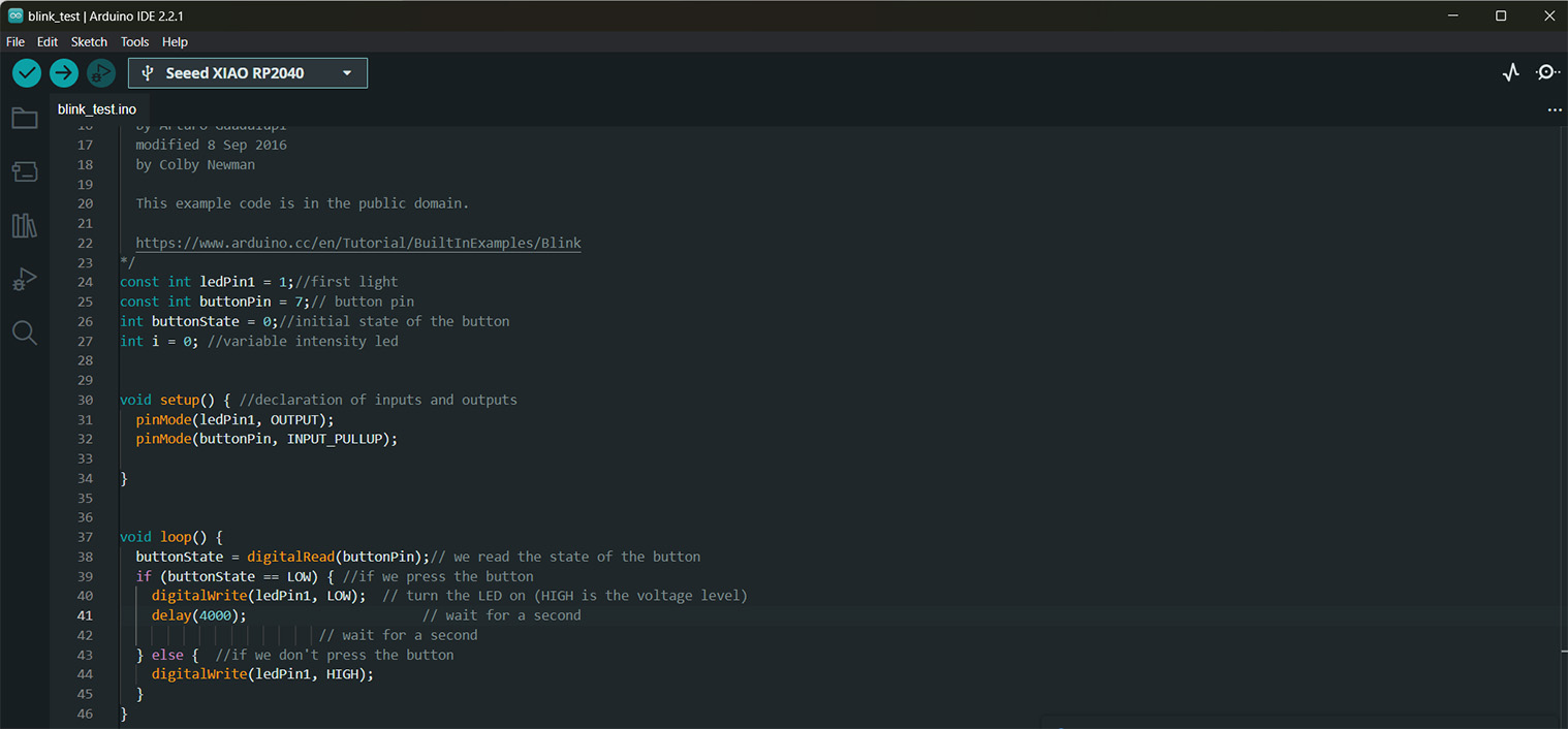
With that done I now can start coding it, thankfully the code that was used for Embedded Programming week is very similar to what I was planning to do for this week, in order to get used to this process. So what I ended up doing was use the code from weeks prior and changed the pins to correlate with the pins I now have components on, and then I took off all the Hello World code that I had before, and one of the delays, then raised the amount of time before the light turns back on to 4000. This code was just supposed to make the light turn off for a short amount of time and then turn back on. Thankfully it worked the first time, probably because it was so simple.