Input Devices
Designing It
Making something for my final so I could get more work on it done. Since I wanted to make a reactive system for sound and vision I thought I should try sound first making a circuit for sound detection.

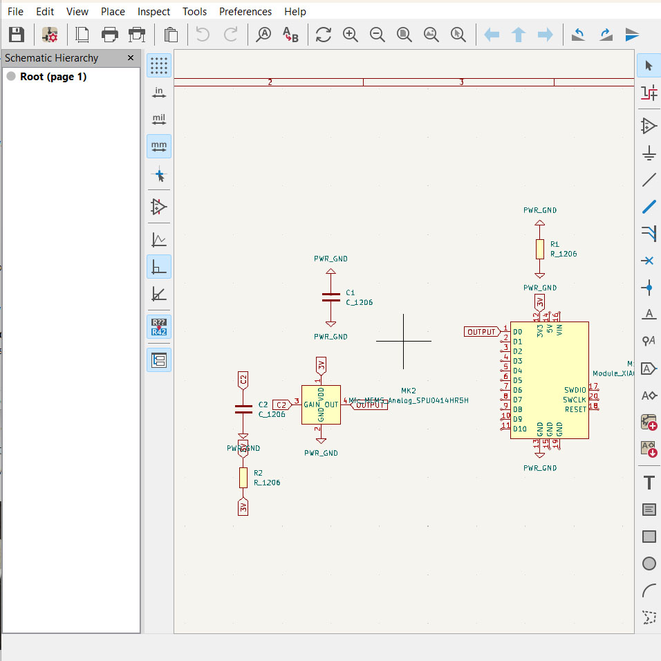
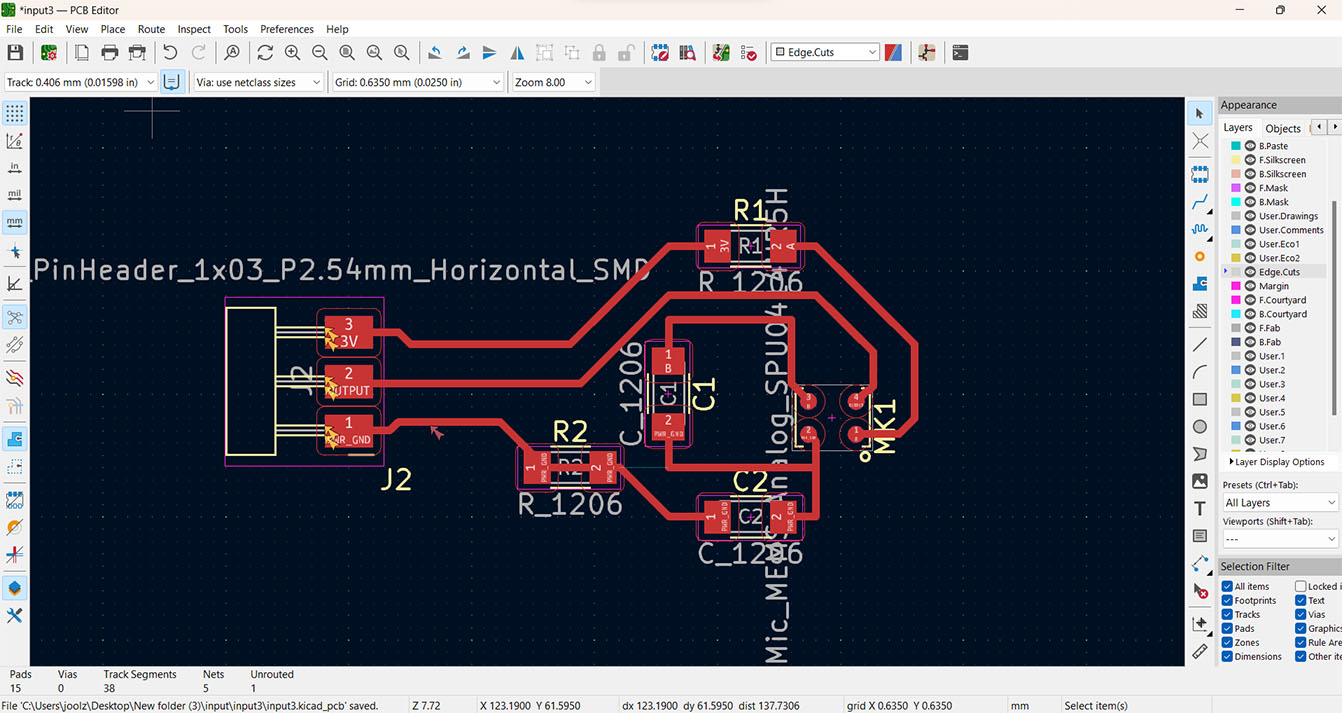
First thing I do is get a microcontroller into the KiCad software I wasn't sure the best one to use so I put in the Xiao RP2040. And tried to figure out what we had in stock so I didn't have to buy anything otherwise, so I put in the MEMS analog microphone, unpolarized capacitors, and 1k Resistors. While trying to figure out what I would need to make it work. I had a friend of mine called Ada try to give me a brief idea of what I need to have in a circuit like this. Which was helpful in knowing I needed capacitors and what to look through to find what I need.
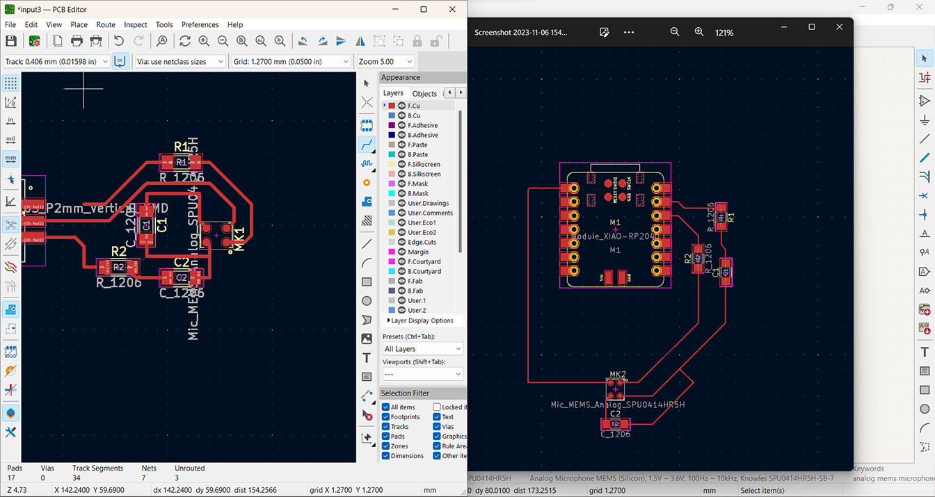
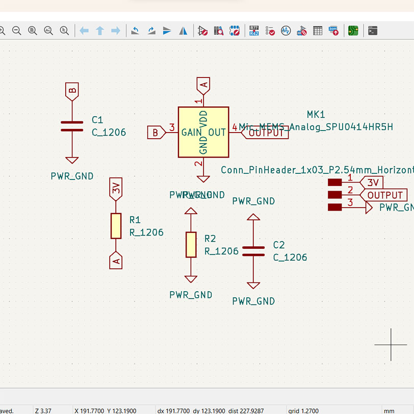
Then with Claire's guidance we thought of a way to maybe instead of the microphone being inside the ear canal, it would be more like an earring and have it be a breakout board instead. So then with advice of Quentin and Claire I was told to rearrange my components to have a capacitor be between GAIN and GND, a capacitor between ADC and GND, and a resistor between OUTPUT and ADC.

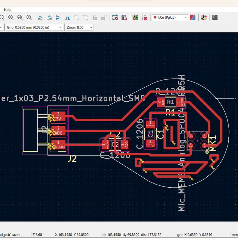
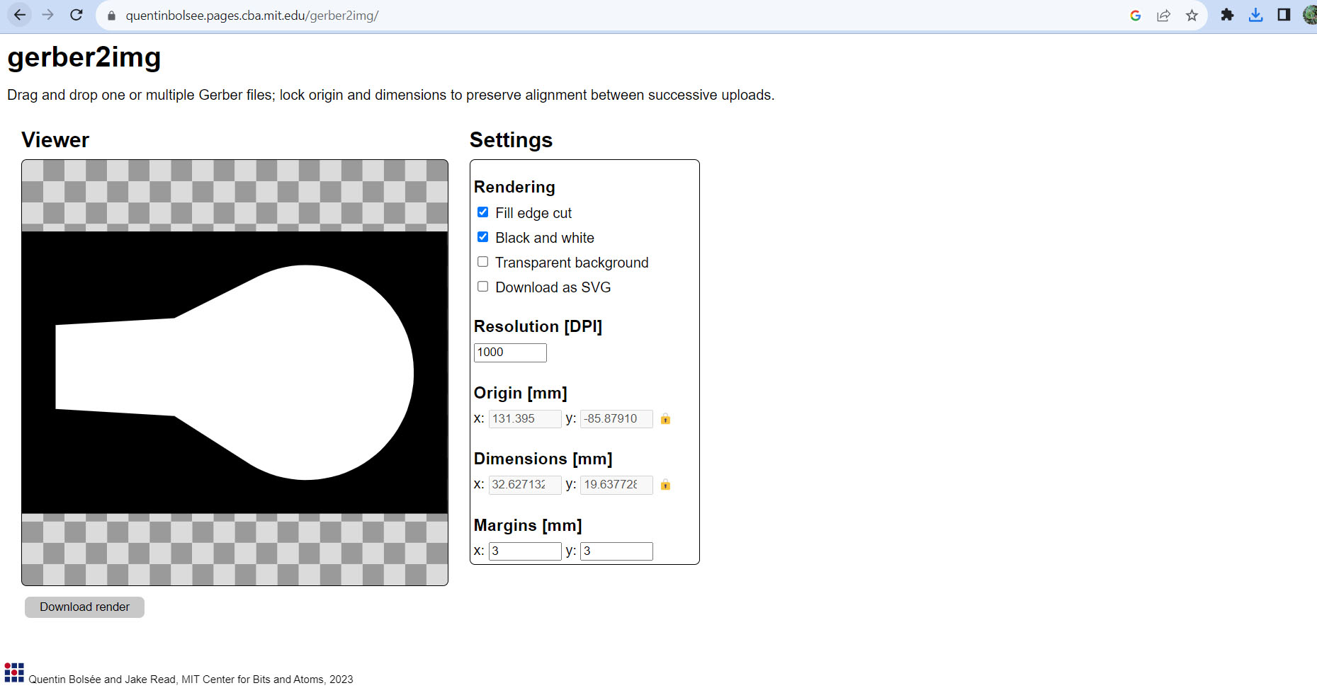
After that I exported as a Gerber file and used Quentin's Gerber converter to make sure the sizing stays the same, and using the MonoFab on Mods I put in the 1/64 bit to the machine and began the milling. It turned out really good, and then changed it to a 1/32 bit which turned out really good too.


What I struggled with was the soldering, because I needed to use a hot plate, heat gun, or the solder paste. While the mics split apart when heated too much so that made it really hard.


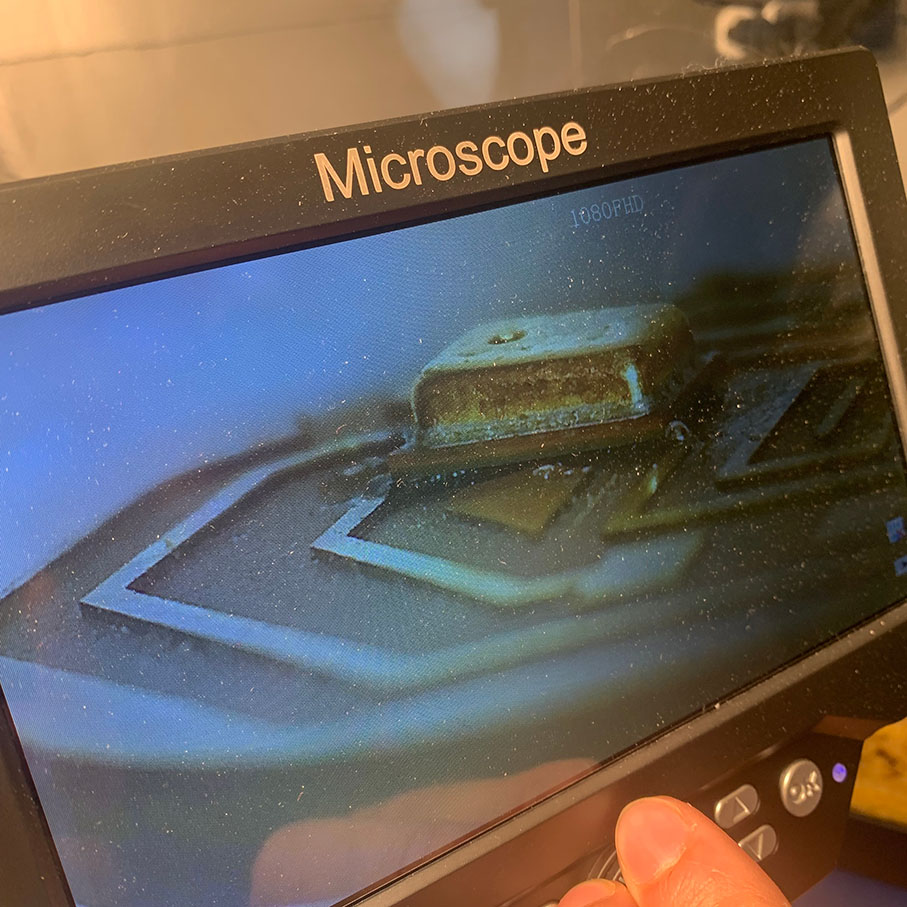
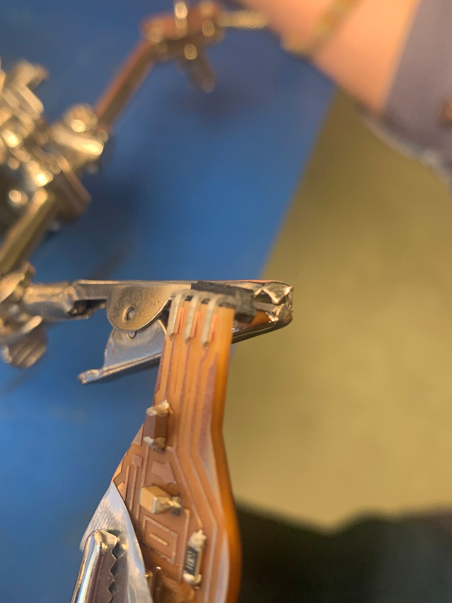
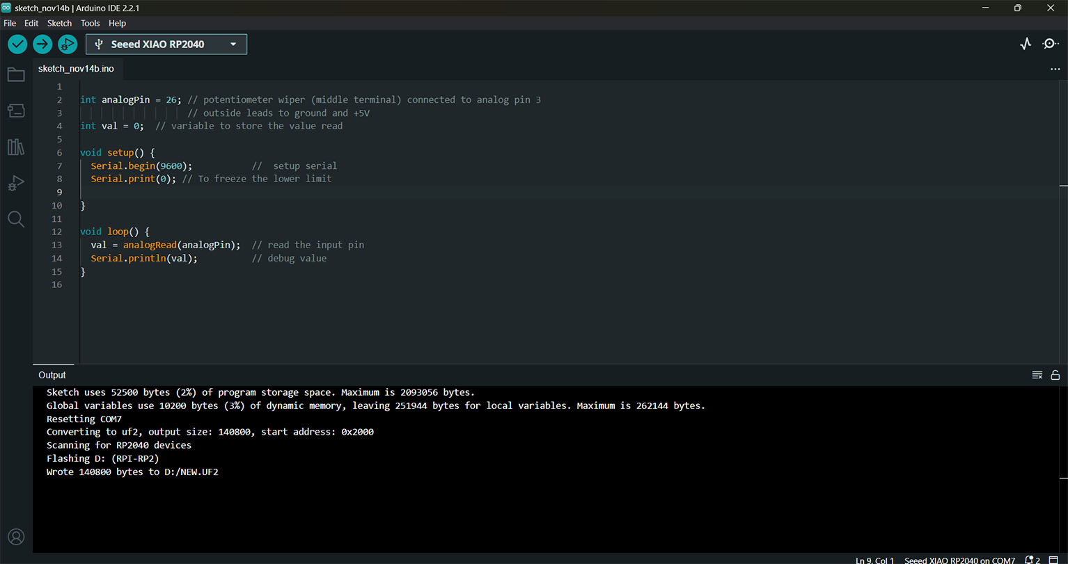
There were so many technical difficulties but with the help of Quentin, and a heat gun that actually works precisely I was able to make my tiny breakout board after soldering all the components on. Then using an oscilloscope Quentin helped me check to see if the microphone was working. It actually worked which was a little surprising. But I wasn't sure how to visually see wavelengths on my computer. So I asked Leo for help and he explained how I just need to read the pin and look at the serial plotter on Arduino IDE. Plugging my beakout board into my main bard with GND, 3V3, and analog pin 26 I then found some example code online from the Arduino website for AnalogRead() and used that to read what wascoming through the microphone. The annoying part was that I couldn't eassily change the range of the plotter in ordere to see the wave from further away.