How to Make (Almost) Anything
Week 13
Task1: Design a machine that includes mechanism + actuation + automation + application, build the mechanical parts and operate it manually, document the group project and your individual contribution.
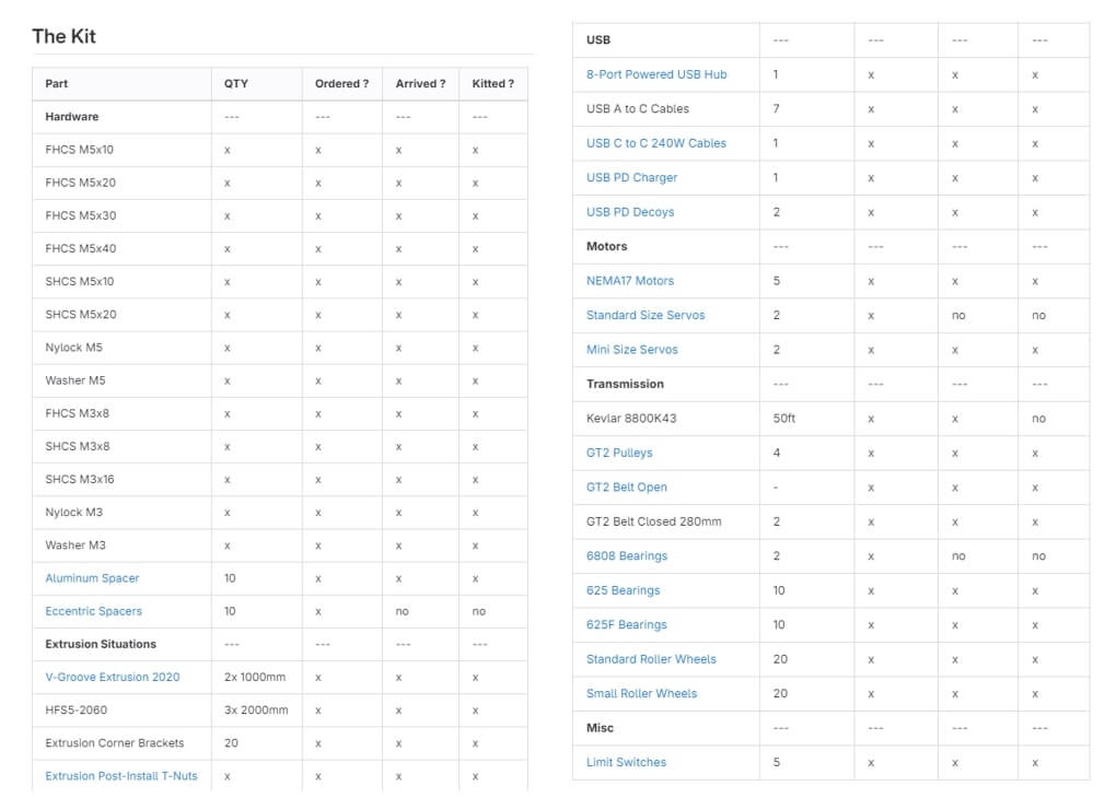
For this week’s assignment, we (Harvard Section) decided to design a CNC, which the design is inspired from Core X-Y [1], that can extrude bleach -PhotoBleach Machine- to make some colorful t-shirts. On my end, I helped for conceptualization of the structural design (3D modelling, kinematics), manufacturing of the parts (cutting aluminum profiles, laser cutting brackets, 3D printing parts), and assembly of the machine. First, I started with reviewing the part list (kit) that is given to us, picture below.
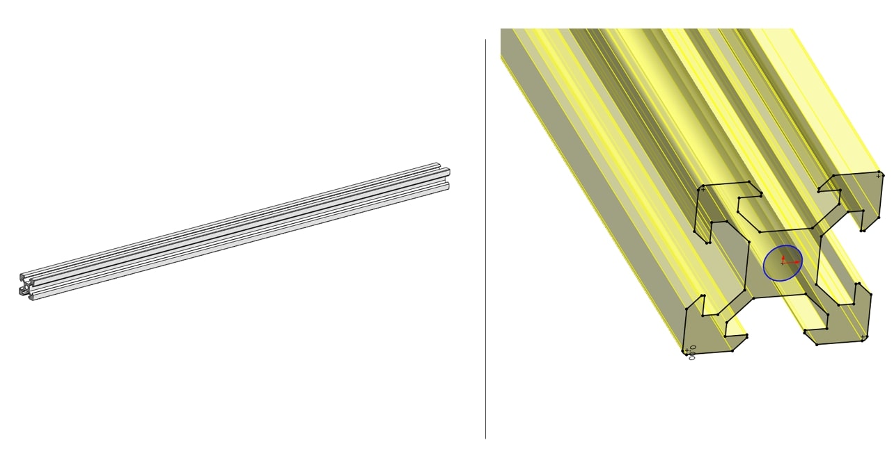
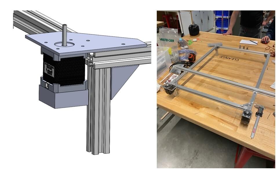
Then I prioritized the structural design (frame) of the CNC, aluminum 20*20 extrusion profiles [1] are given and I found the CAD model [2] of them and start conceptualizing in SolidWorks, shown below:
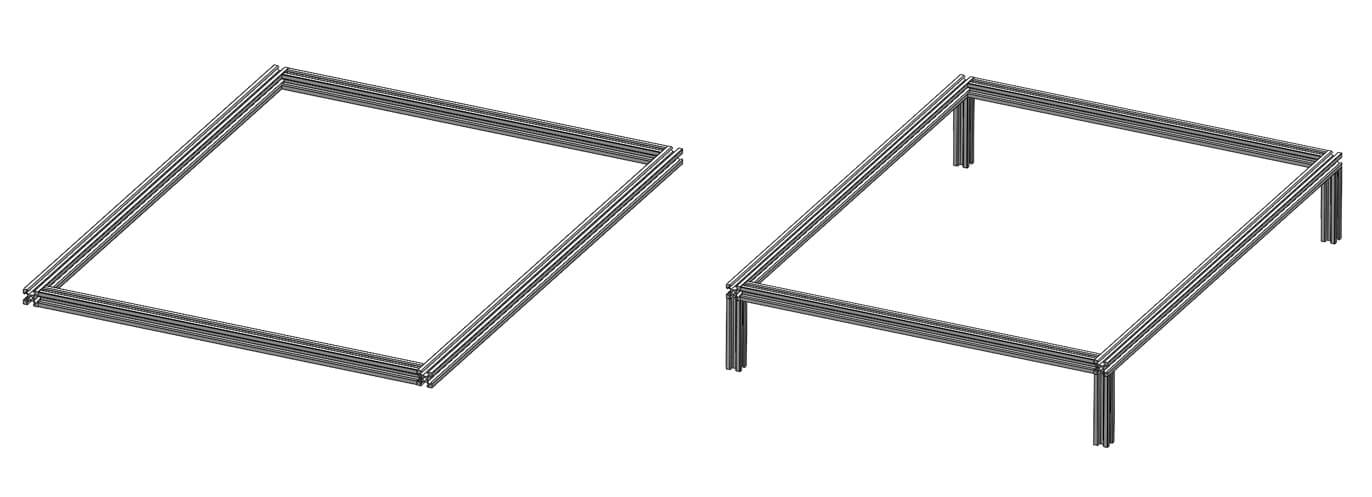
After that we decided the size of the frame (based on a t-shirt size-M), which x: 500 mm and y: 700mm. After that I conceptualized the frame shown in below:
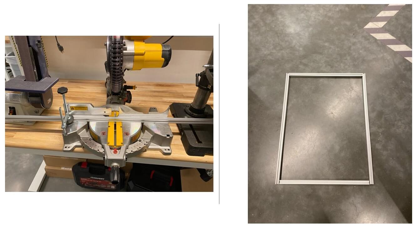
After this I cut the profiles into desired lengths by using miter saw.
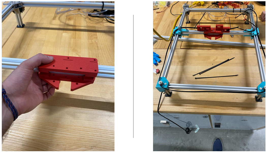
After that I designed the laser cut file for stepper motor corner bracket, t-nuts are provided us to use to secure the brackets on to aluminum extrusion profiles, so we used t-nuts and M5 bolts for brackets.
We modified the 3D printed parts provided us and used heated insert.
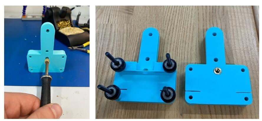
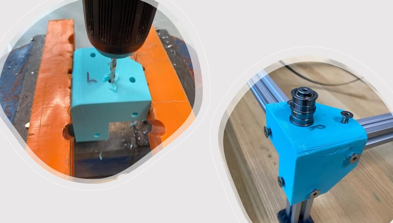
After this I helped to assemble the parts printed overnight, those are corner brackets, first I enlarge the holes and put the heated inserts and then assembled them on to the aluminum extrusion frame with T-nuts and bolts. Below pic:
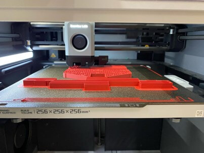
In the meantime I gave the 3D print parts for X axis carriage (part that will hold the nozzle and move on the X axis).
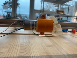
After that I designed an acrylic piece for pump to mount on to the aluminum extrusion frame, I used M5 bolts and t-nuts x2, to mount on to the frame, and M3 bolts and nuts x2, to mount the pump on to the acrylic piece.
While I was waiting for the parts to print, I wanted to check the kinematics, so I zip tied the belt to the frame and looked at the kinematic motion to see if everything is okay.
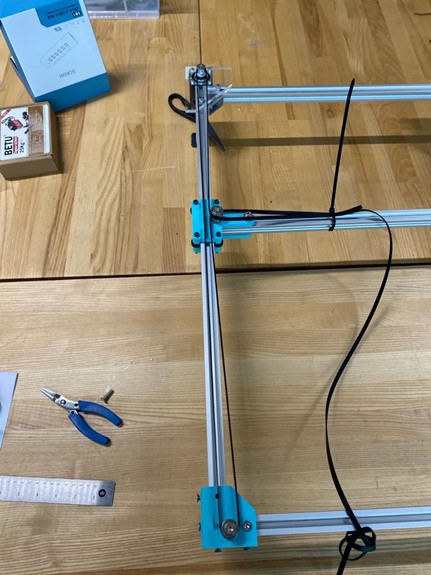
Below is the video that shows the kinematics check of the mechanism:
CAD files I designed: x
References:
[1] https://www.corexy.com/theory.html
[2] https://www.amazon.com/Aluminum-Extrusion-European-Workbench-19-7Inches/dp/B0C3DBQ2GR/ref=sr_1_3?keywords=20x20%2Baluminum%2Bextrusion&qid=1701567312&sr=8-3&th=1
[3] https://grabcad.com/library/aluminium-profile-20x20-1