How to Make (Almost) Anything
Week 3
Task1: Introduce your microcontroller board:
In the 3rd week of the class, we asked to use microcontroller and learn embedded programming, so I chose the RP2040 and Raspberry Pi Pico W, because it has more pins than the other options we have (SAMD21 board, and ESP32-C3). This board is a new board from Raspberry Pi with Wi-Fi capability, it allows users to connect and send receive signals wirelessly [1].
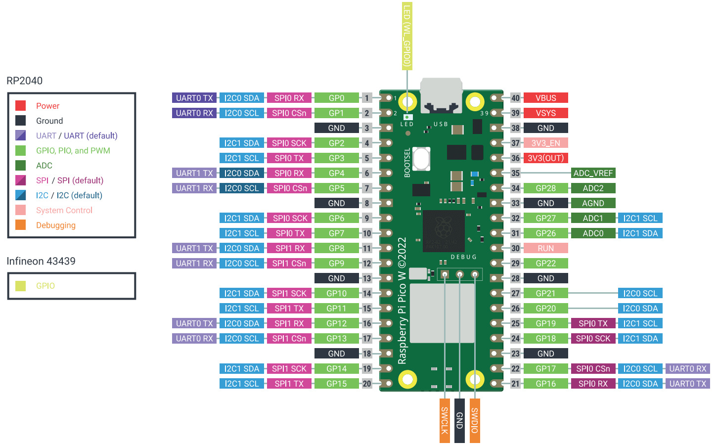
Below is the pinout for the Pico W. It can be seen it has 3 analog input pins (31, 32, 34) which is very useful for sensor projects, and it has many digital output pins to control various components such as LEDs, motors, etc.
Task2: Look through the data sheet for RP2040:
First, I looked through the datasheet (very long pdf) of the RP2040 which is the microcontroller being used in the Pico W. Here is the link that I used for this: https://datasheets.raspberrypi.com/rp2040/rp2040-datasheet.pdf [3]. It is important to learn the microcontroller capabilities because it can be used as manual for learning the different functions of the microcontroller as well as it is mins and max.
Task3: Write a program, blinking the LED on the Pico W board, in Thonny and Arduino IDE.
Thonny:
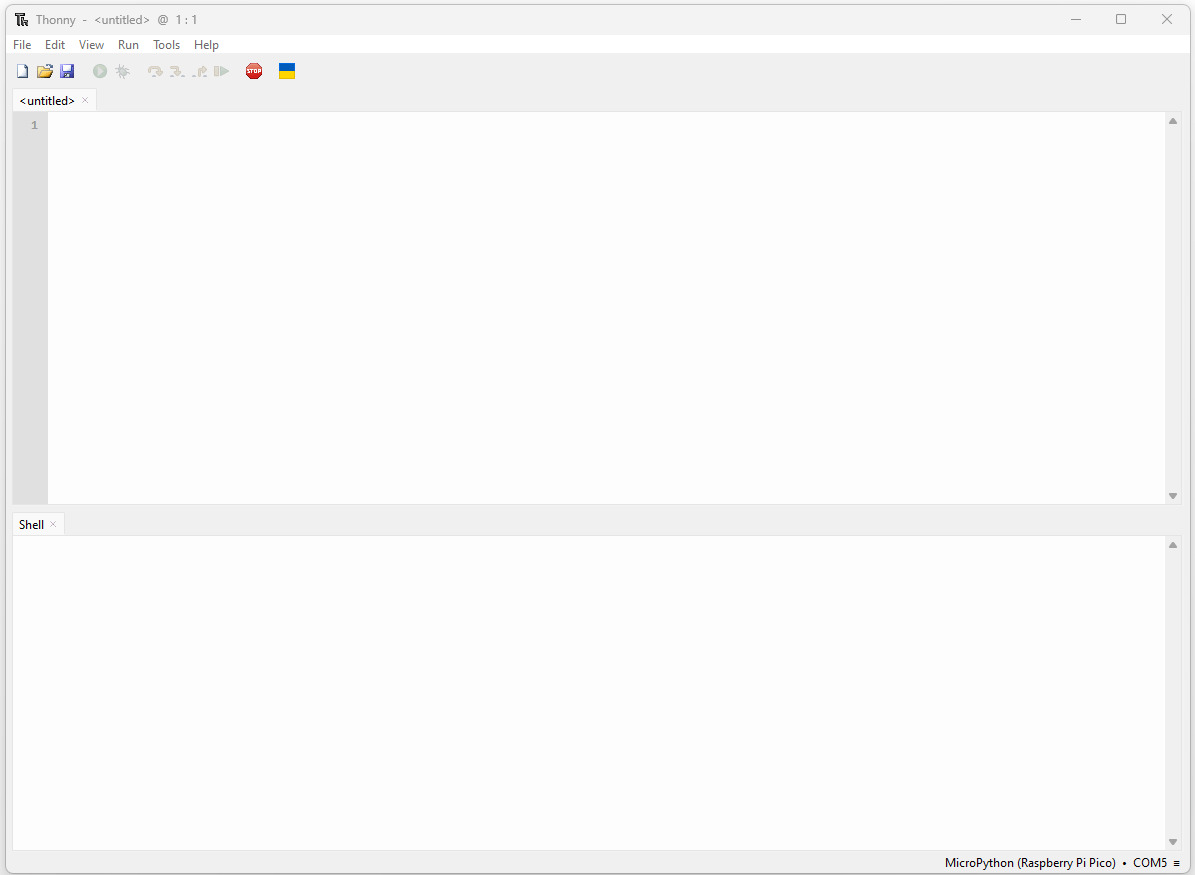
Thonny is a free Python integrated development environment (IDE) that is designed for beginners. It has a built-in debugger that can help when you run into bugs. I downloaded the Thonny here, https://thonny.org/ [4], windows edition. The user interface is friendly, and it looks like this in the first place.
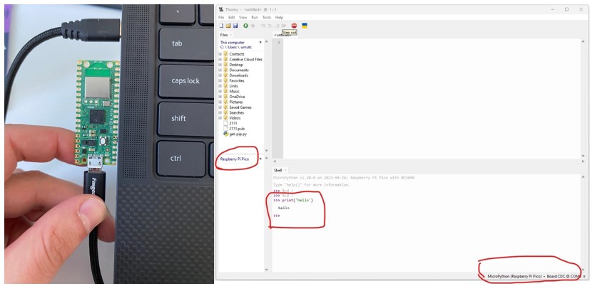
After I connected the Raspberry Pi Pico W to the computer with USB-C cable (press the bootsel button while connecting it), I open the Thonny and set up the micropython for Pico W and Thonny communication. Below is the picture after setting up the software and hardware communication, it can be seen on the left bottom of the picture, it says micropython and com port and Pico W, means that board is connected and ready to program.
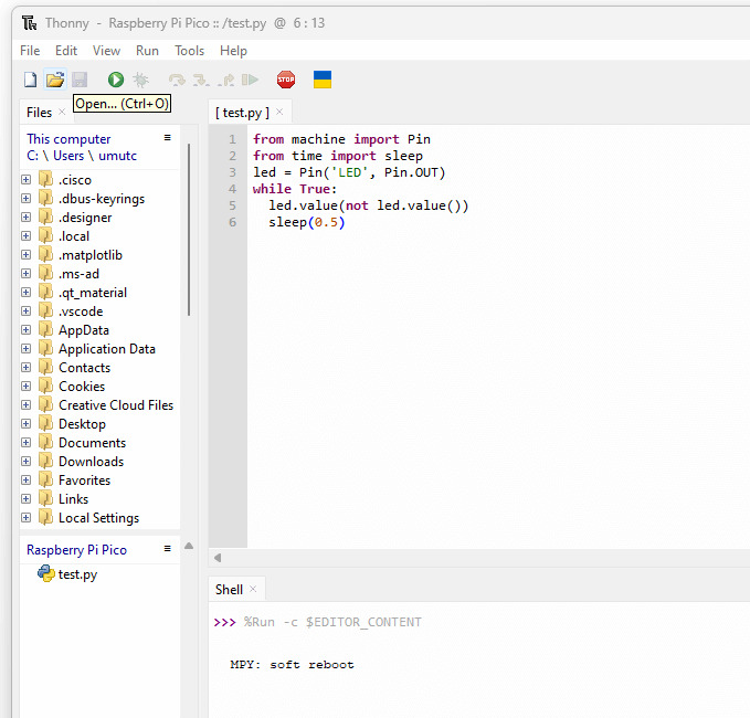
After setting up and making sure software and hardware is communicating, I wrote a code block that Ons the LED Pin (OUT means it will output voltage to that Pin) and putting a sleep buffer for 0.5 second will blink the LED.
Arduino:
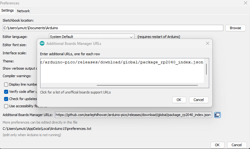
After I played with Thonny, I decided to try Arduino IDE for Raspberry Pi Pico W, to do that I needed to install some packages. First, I found a GitHub repo for Pico drivers to install to Arduino IDE (link: https://github.com/earlephilhower/arduino-pico/releases/download/global/package_rp2040_index.json ) [5], below picture shows where to paste this link (go file -> preferences -> additional boards manager URLs).
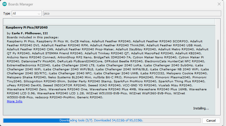
After this step, I installed the library for Pico W, called Raspberry Pi Pico/RP2040.
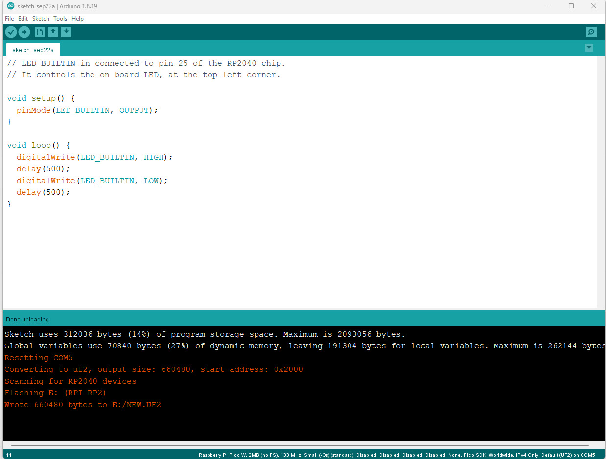
And here is the simple code block to blink LEDs in Pico W using Arduino IDE.
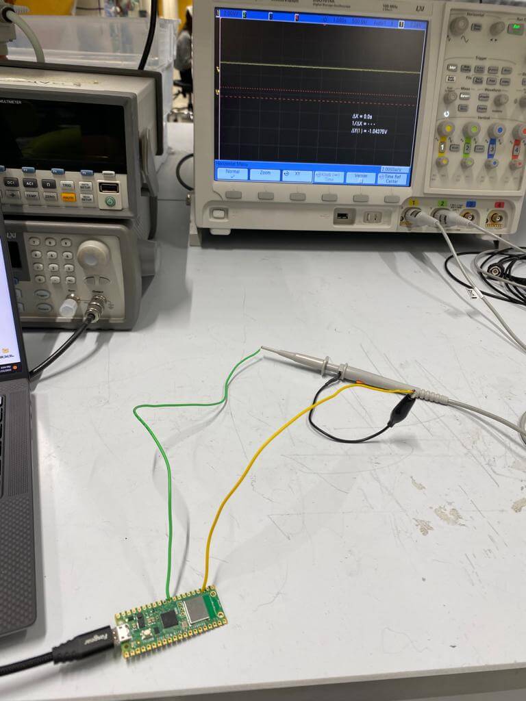
Task4: Connect Pico W board to the oscilloscope and measure the digital output signals and waveforms.
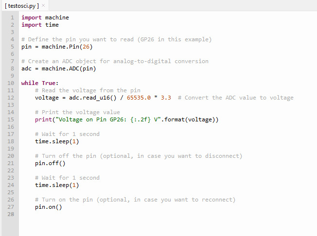
After learning the above steps, I connected the Pico board to oscilloscope so that I can read the voltage, below is the example code and picture for oscilloscope reading.
References:
[1] https://projects.raspberrypi.org/en/projects/get-started-pico-w
[2] https://www.raspberrypi-spy.co.uk/2022/11/pi-pico-w-pinout-and-power-pins/
[3] https://datasheets.raspberrypi.com/rp2040/rp2040-datasheet.pdf
[4] https://thonny.org/
[5] https://github.com/earlephilhower/arduino-pico/releases/download/global/package_rp2040_index.json