How to Make (Almost) Anything
Week 6
Task1: Make and test the development board that you designed to interact and communicate with an embedded microcontroller.
For this week’s assignment I wanted to design a breakout board so that I can easily plug and test off-the-shelf sensors and input output devices. I used Xiao Rp2040 for the microcontroller and input output headers for the PCB design. I used Fusion 360 as the PCB design software, and I imported fab lab libraries for the smd components.
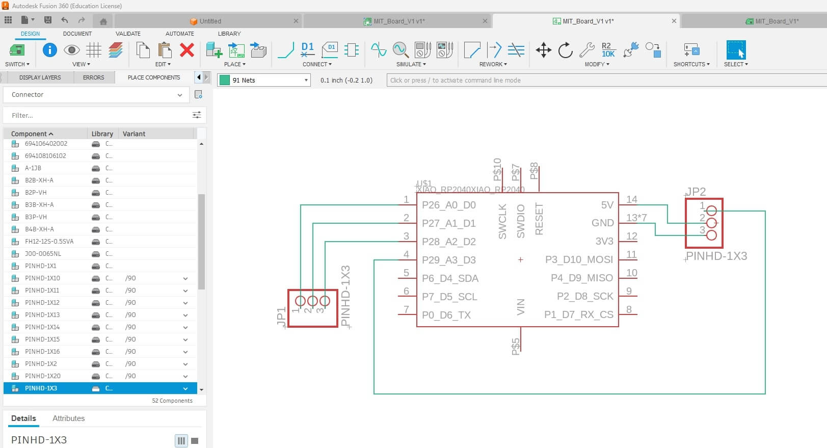
After designing the schematic, I switched to PCB layout interface, and I connected to traces to the tabs and pins according to my schematic design.
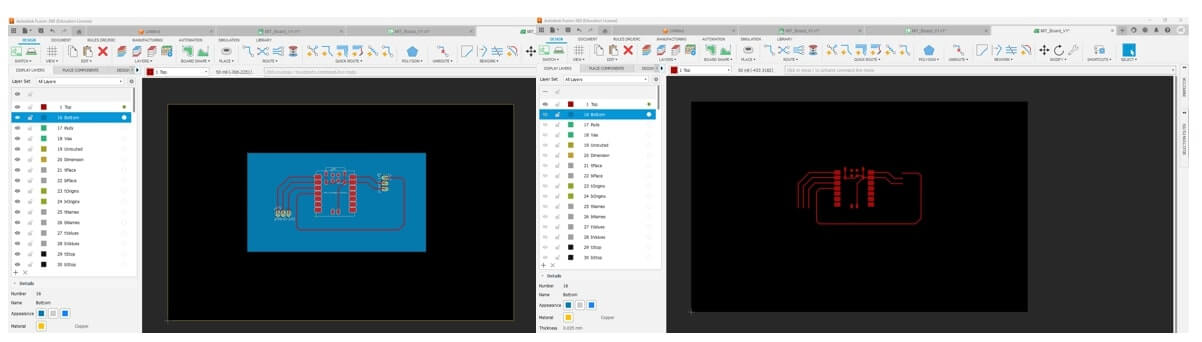
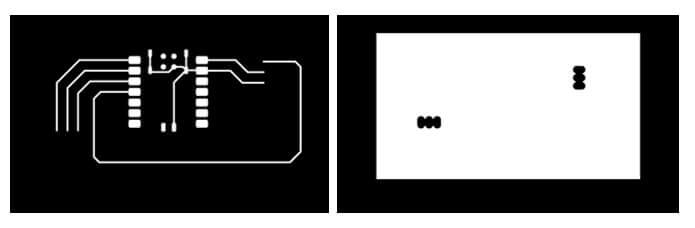
After that I exported the trace layer and outer layer for the PCB, below are the pics.
I used Mods for machining the PCB and Roland SRM 20-mil, Mods [1] is a user-friendly interface, first I go to website and right click for the programs, and I selected Roland SRM-20 mil PCB option. Then I imported the traces png file I created. After that I clicked mill traces and calculated the toolpath and I connected to the Rolan machine. To secure the copper board to the CNC bed I used double sided tapes, and I changed the tool to fine drill bit to machine the traces.
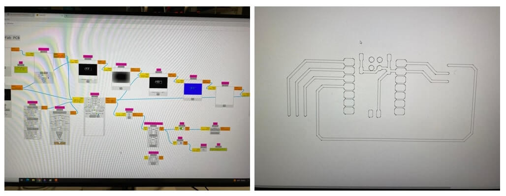
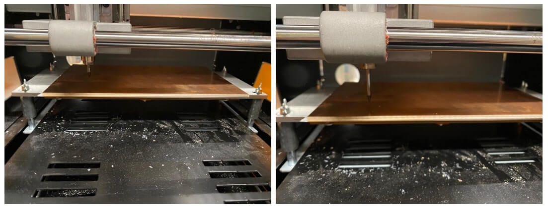
After that I sent the toolpath to the machine, and it started, it took 20 min to finish the board.
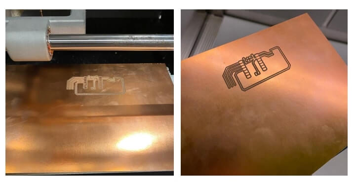
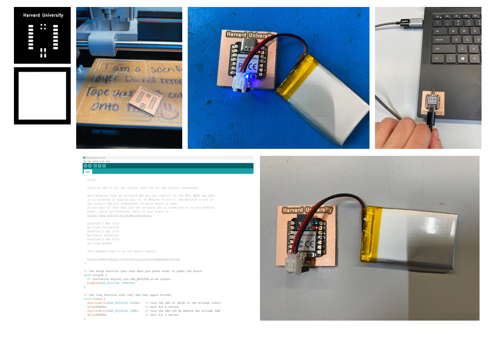
After I struggled a little bit with Fusion to design the PCB (I could not cut the edges), I decided to use KiCAD [2] to design a simple PCB. All the rest of the process is remain same (using Mods and Rolan SRM20), I only changed my design software. Below is the designed and manufactured PCB, and LED blinking example.
References:
[1] https://modsproject.org/
[1] https://www.kicad.org/