How to Make (Almost) Anything
Week 9
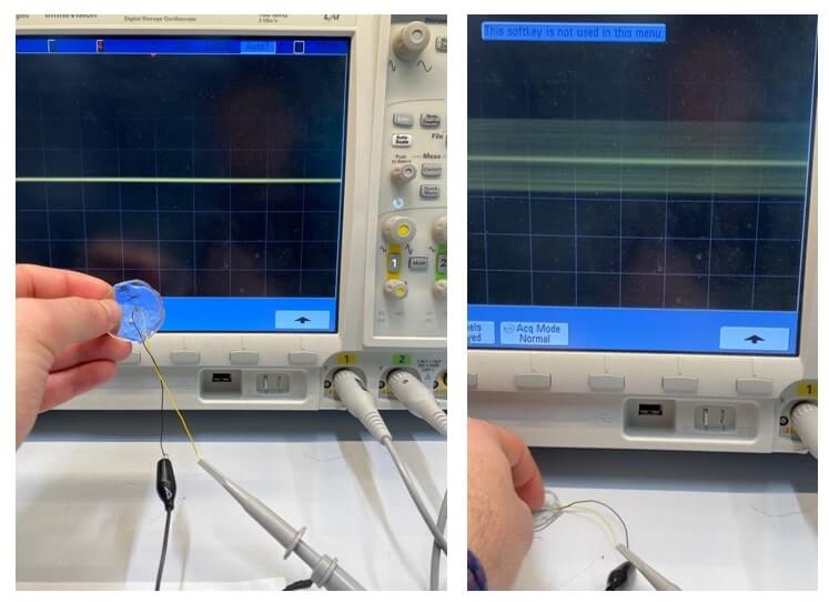
Task1: Group assignment: Probe an input device’s analog levels and digital signals.
I connected the oscilloscope’s probes to piezoelectric material and since they can produce voltage against applied strain or mechanical shock, I tracked the changes on the screen.
Task2: Individual assignment: Measure something: add a sensor to a microcontroller board that you have designed and read it.
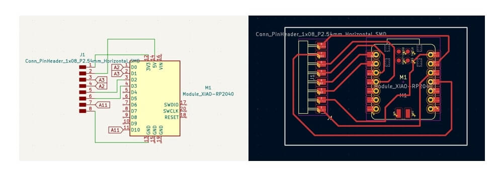
In this week’s assignment I wanted to use a flex sensor [1] as an input device. So designed a breakout board that has the Xiaorp2040 and a jumper wire connector so that I can connect different type of sensors if needed. Below is the picture of the board schematics and PCB. It is important to note that I used 0.406 mm trace thicknesses and distance between the traces as design rules in this PCB design.
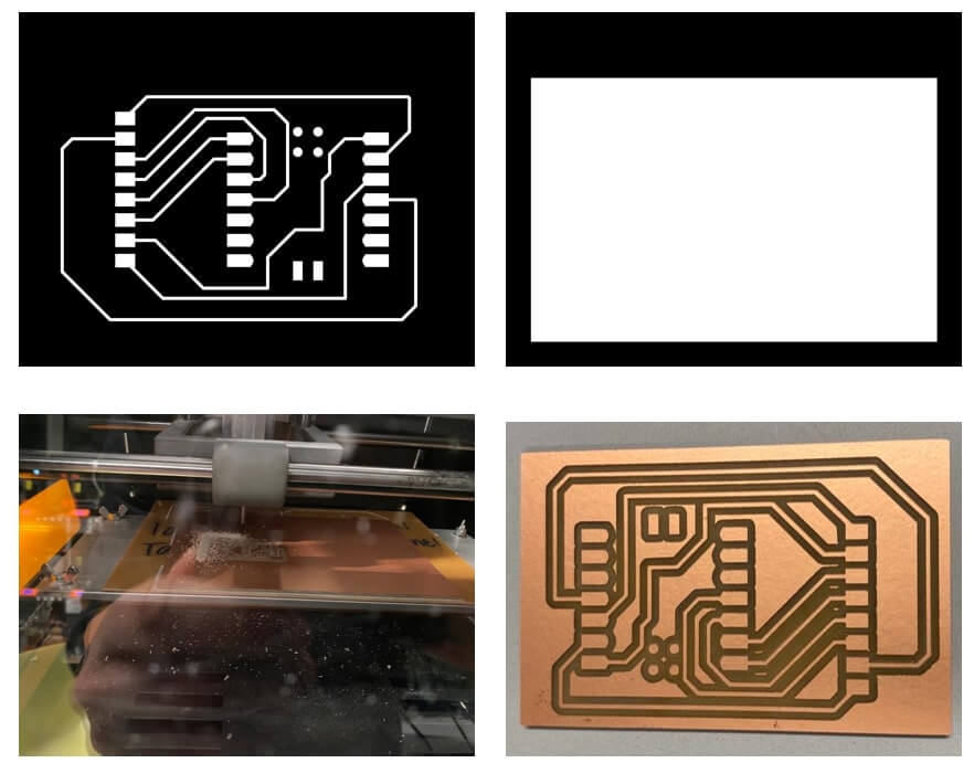
After that milled, I exported that Gerber files and imported them into the GitHub page provided by TA in the class [2-3]. Below is the picture of exported files and milled PCB by using Mods [4] with guideline provide by here [5].
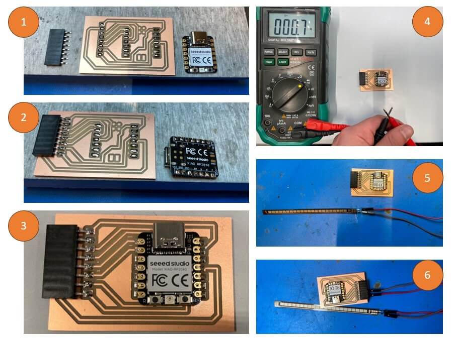
After I cleaned the PCB, I soldered the tabs to make it easy to place the components (1), I did not use any flux. First put the jumper wire connector with tweezer and heated up the solder with solder iron and repeated for each tabs (2). I repeated the same steps for Xiaorp2040 (3). At the 4th step I wanted to check the connectivity -which is very important before spending time to connect any sensor and do coding-, and everything was fine (4). In the following step I soldered jumper wires to flex sensor I have (5). Finally, I connected the cables to the board! (6).
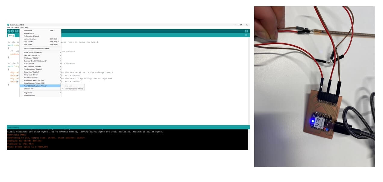
Now it is time to test the device! So, I connected GND and Analog & input pins (A0) and power 3.3V, and I used Arduino to program and track the voltage level on the screen. I plugged the Xiaorp2040 to PC and used Arduino to connect to COM port and test a simple blink test script to check if it is working or not.
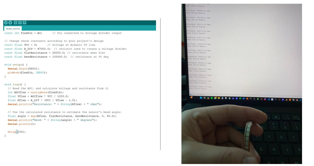
After this, I uploaded the code below to check the voltage change in the flex sensor!
References:
[1] https://www.digikey.com/en/products/detail/spectra-symbol/FS-L-095-103-ST/2175377
[2] https://gitlab.cba.mit.edu/classes/863.23/site/-/issues/30
[3] https://quentinbolsee.pages.cba.mit.edu/gerber2img/
[4] https://modsproject.org/
[5] https://gitlab.cba.mit.edu/classes/863.23/Harvard/harvardsite/-/issues/13