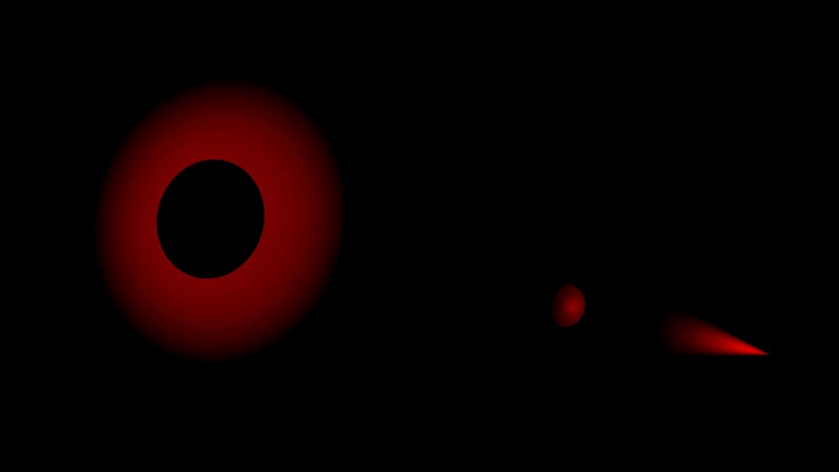
It's a stimulation device that fragments the shadow of whatever it projects upon.
Task 1: Ideation
Design and plan a potential final project. The final project should be a 'masterpiece' that integrates the topics found in each week of the class. This includes:
- Computer-Aided Design
- Computer Controlled Cutting
- Embedded Programming
- 3d Scanning and Printing
- Electronics Design
- Computer Controlled Machining
- Electronics Production
- Molding and Casting
- Input Devices
- Output Devices
- Networking and Communications
- Interface and Application programming
- Mechanical, Machine Design
- Wildcard ??? Tbd.
My tentative response to this prompt is that I would like to make a projection device. I've been thinking a lot lately about the shadows of tree branches. I believe that the projected shadow of the tree branch is one of the most OG images in our aesthetic lexicon, and is one that has undergone many mutations since the onset of artificial lighting. If the cast shadow of a tree at high-noon or full moon was the starting point of this semiotic history, then the advent of fire marks a distinct evolution in our aesthetic palette. It brings to the branch-image a series of flickering superimpositions, each of variable orange gradient, confounding the perceived stability of the branch in question. When whale fat was used to power streetlamps in the early 19th century, a distinct yellow amber glow would surround the branches silhouette. A number of other illumination technologies would follow: carbon-arc, tungsten-incandescent, coal-gas, gasoline, mercury-vapor, each inventing, as if by accident, an additional branch-shadow. Due to market competition, new advancements, and regulation in the lighting industry, many of these lights and their corresponding branch-shadows will get relegated to particular countries, juridictions, and applications. These contexts eventually embed themselves in the semiotic content of the branch-shadow itself. For example, when incandescent lamps were deemed too dim and red to enable effective street-side survellience in, low-pressure sodium bulbs began being marketed for their crime fighting potentials, bathing low income minority neighborhoods across the world in a fresh acrid yellow hue. Complex interplays between new technologies, their marketing strategies, and local policy eventually deposit themselves upon the same image once considered by our most ancient ancestors. Soon after the LED was invented, it achieved market dominance for new streetlighting efforts. It would even going so far as to replace much of the working infrastructures already in operation, due to its low operation costs. Following the LED, for the first time, the branch-shadow will be cast into a gridded pattern, projecting the sign of our immutable, organic origin into a completely artificial, humanly-ordered arrangement. You can observe this branch-shadow all across the Cambridge ground at night.
I would like to treat this as the site for my proposal. Instead of the normal business of inventing new light, and incidentally inventing new shadow, I would like to make a projection machine that attempts to directly manipulate the projected image of the shadow. It needs to be able to adjust the color, position, and scale of the shadow.
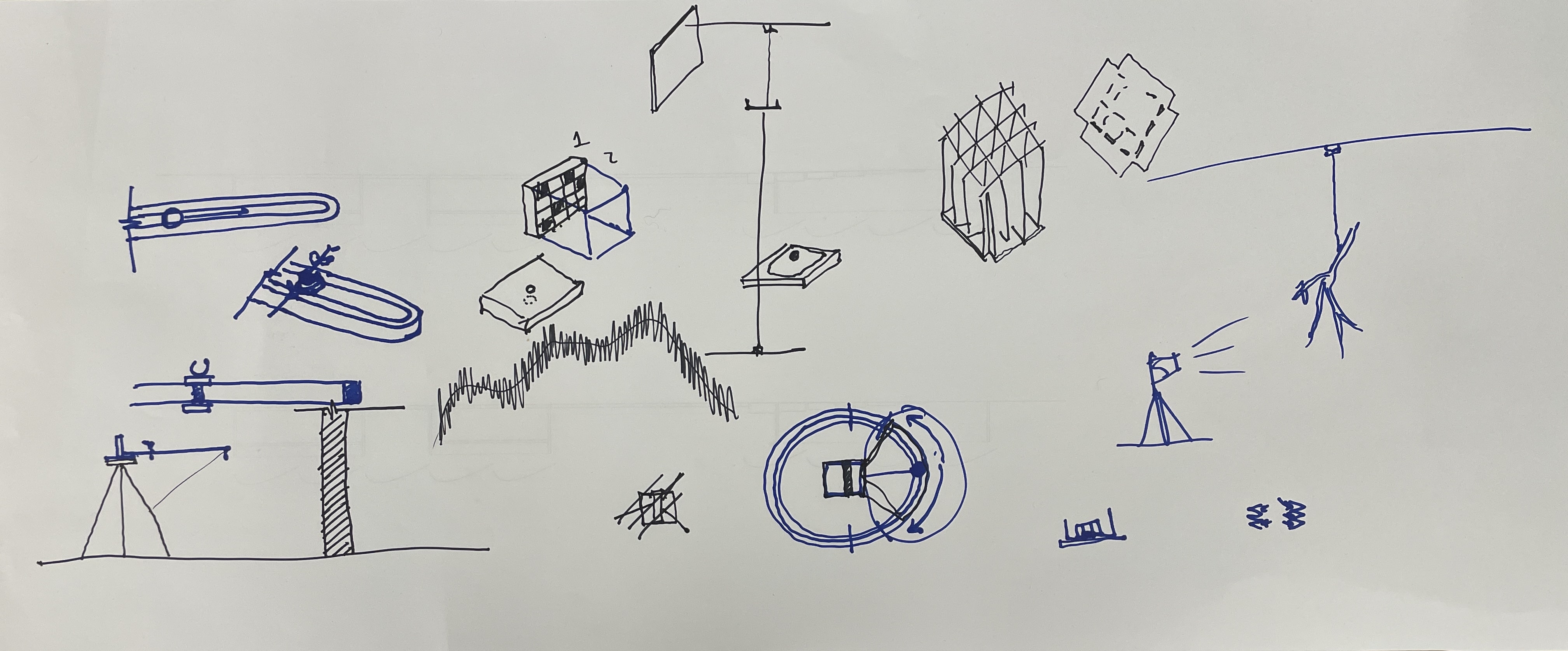
Early Sketches
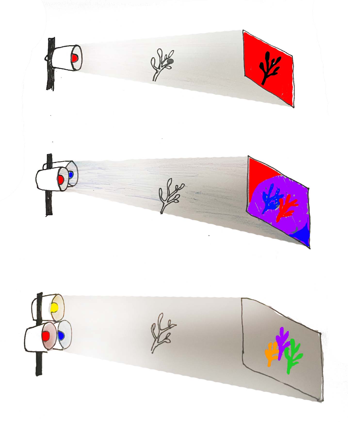
You can control the color of the shadow by having some colored light hit the projection screen, and having others blocked by the object, producing a the shadow. The lights begin to have these curious inverse relationships.
In order to control the position of the shadow, I thought either to have three spotlights that move on tracks, or have a grid of spotlights. One reason for favoring the moving lights is that I would learn how to do that. One reason for not doing it is that the axis coordination infrastructure would cast shadows when a light would eventually pass beneath it. Perhaps there would be a way to engineer this out, but I would rather get deeper into coding the light than coding the movement. So for this, I think a grid works better, and still enables the movement of the shadow, albiet not gradual movement.
Here's a mockup of how the light projector could work. While lower-power LEDs can be color controlled with RGB channels, I want each light to have enough lumens to function as a spotlight. Because of this, I think it will be best to introduce light in an analog way, by placing gels in front of some of the lights.
Task 2: Figuring it Out
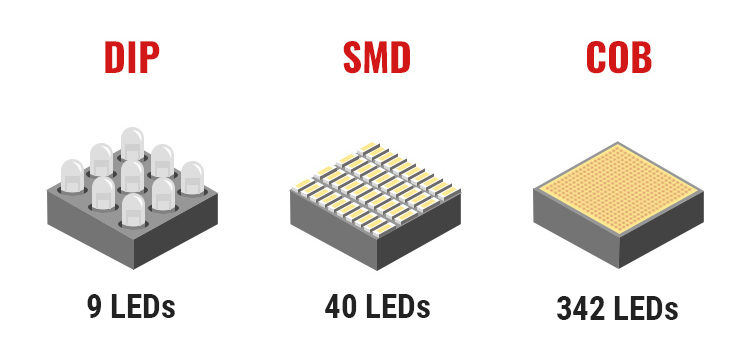
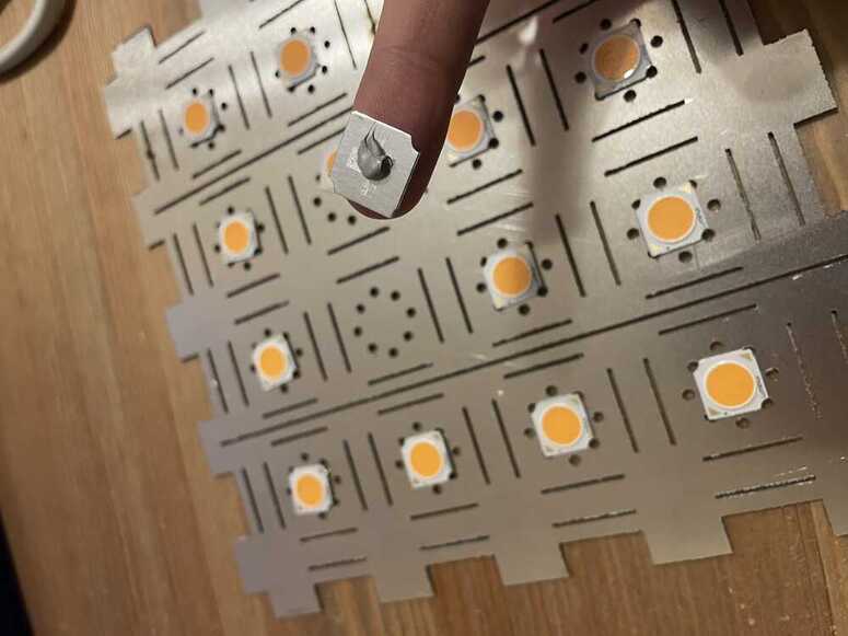
COB LEDs are a relatively new consumer technology that can deliver massive amounts of light with relative efficiency. They stand for "chip on board" , and they consist of a large array of LED chips very closely packed, with a single phosphor coating atop.
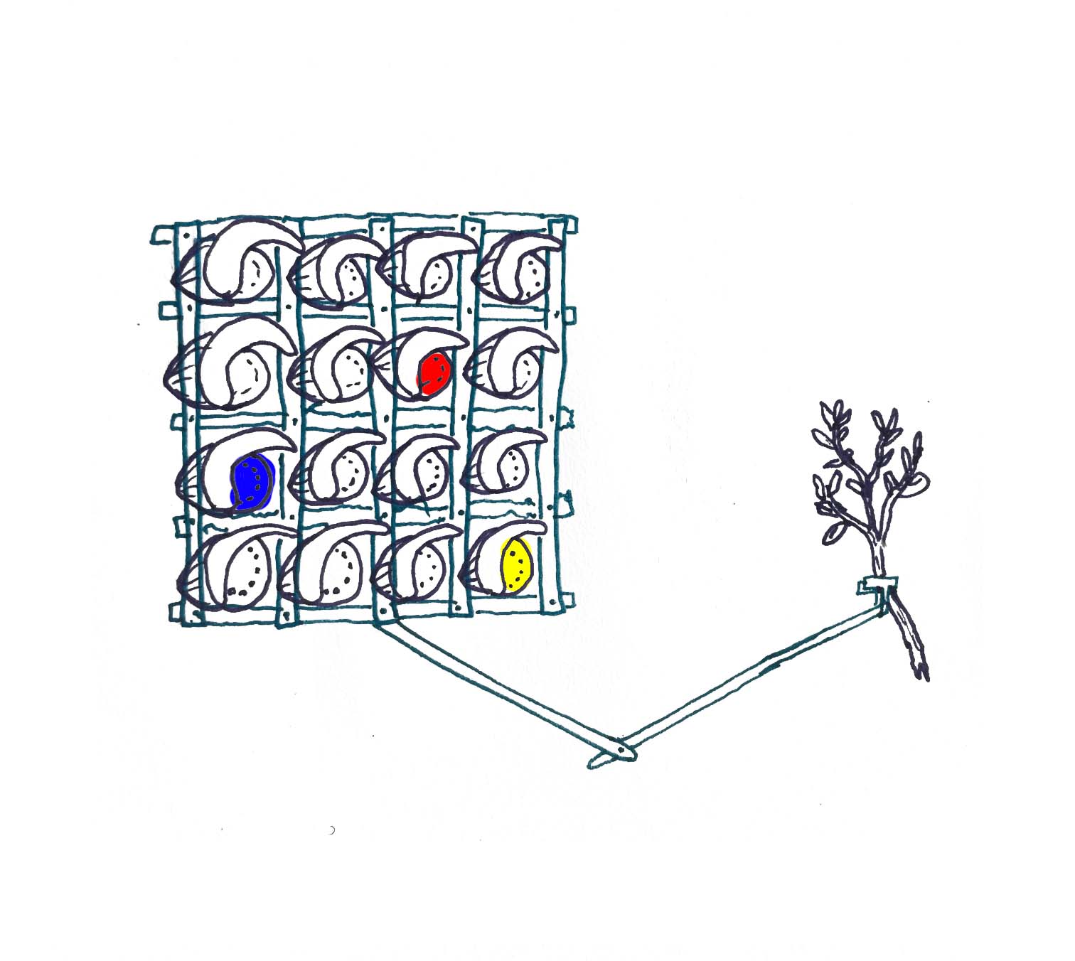
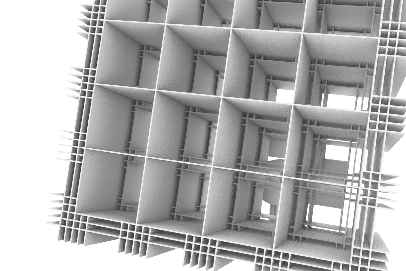
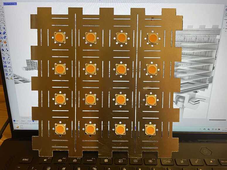
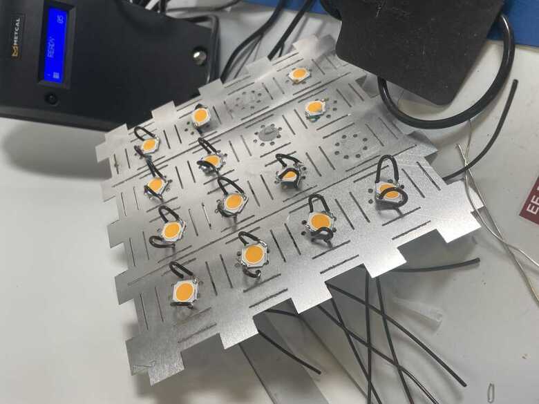
While the COBs are relatively efficient, they still produce a lot of heat. This is a problem, because as they produce more heat they draw more power, and you can get into a situation called thermal runaway which essentially results in the LED exploding. We don't want that. This is generally fixed by having an aluminum heat-sink. I want each of these lights to function as a spotlight, so I designed a case for them that can function as a heat-sink all the while making the light from the COBs more directional. The high surface area design helps the heat to dissipate. 16 COBs sit in a 4x4 array, and the distance between them allows you to control the position of the shadow.
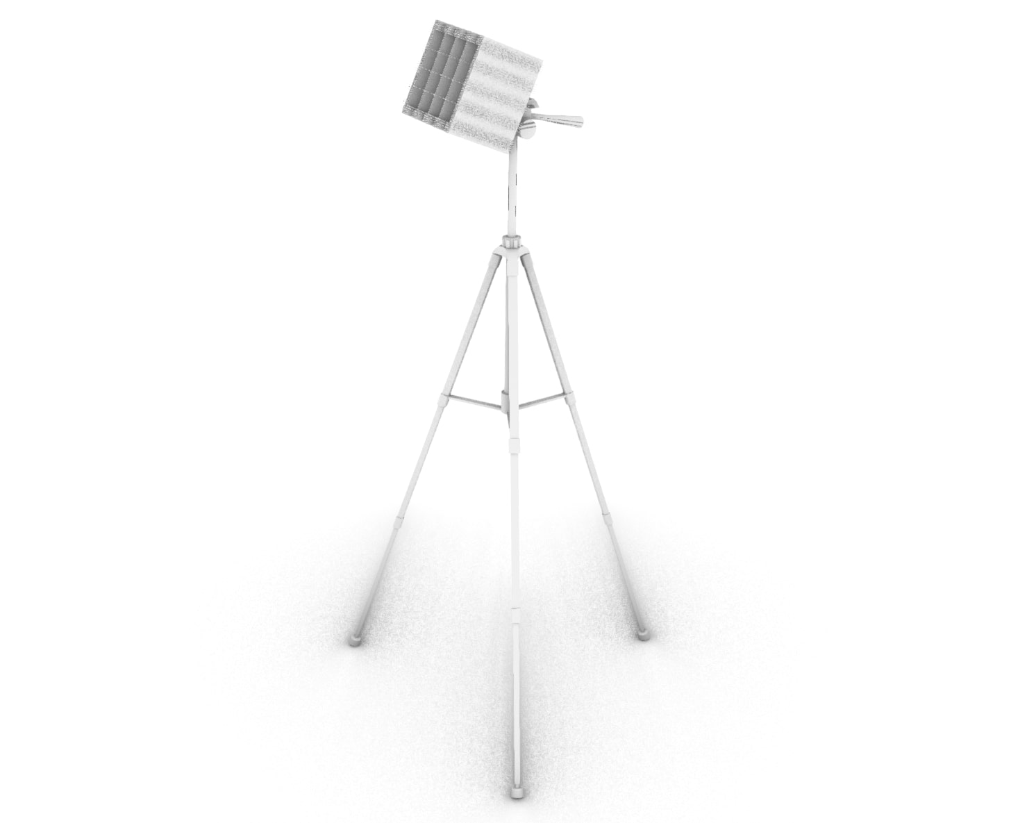
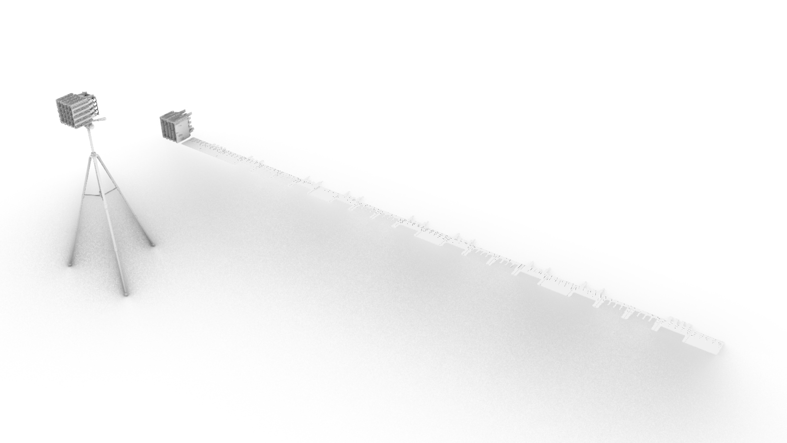
I want to design it to attach to a tripod, so that it can be set up freely within a room.
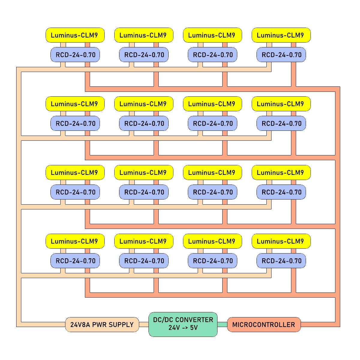
During electronics design week I started to plan out how a 4x4 array of LEDs could be powered by a high power source, all the while being controlled with a microcontroller. My means for doing this was to use NMosfets as a gate, and to use the pins to control whether or not that gate is open. In this design I didn't actually use a high power source, given that I wanted to simply test this with the LEDs provided in the inventory. While the mosfets aren't really needed at this power level, and I could just drive the LEDs with the voltage from the microcontroller pins, I wanted to test out this halfway design.
I tried fabricating it during electronics production week, didn't finish, and came back to it during outputs week.
The lights turned on, which was a momentary success, but they oddly all turned on the moment I plugged them into the computer. I was expected to need to trigger the mosfets before any of the lights would turn on. I tried using the multiplexer to resolve this, setting all the outputs to LOW, but nothing would turn the lights off. TA Leo checked it out, we brought out the multimeter, there weren't any shorts, and the voltage drops across the mosfets didn't cue us in to what was going on. We were stumped, but it was time to move on.
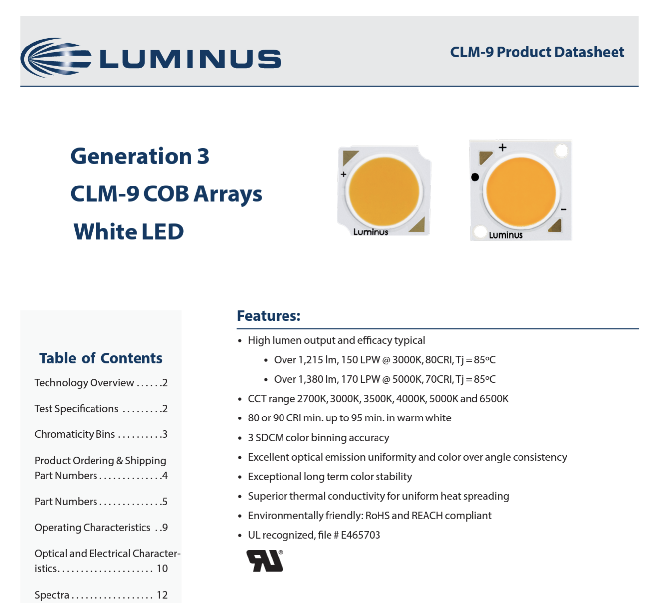
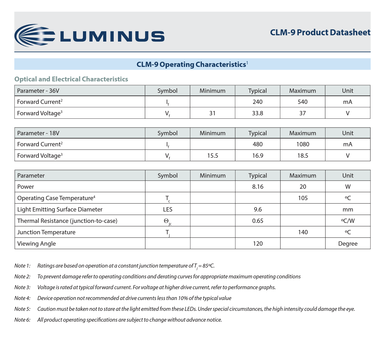
These COBs are only $3.5 on Digikey. Their datasheet shows two different power scenarios, each of which max out right before 20W. So this is the limit to keep in mind. There is a good web of tutorials here: https://ledgardener.com/cob-led-basics/ . This blog explains how a heatsink is required, as well as either a voltage or current driver. These drivers regulate either the current or the voltage, setting a maximum threshhold. So when I jump up in power, I will need to pair these COBs with a driver.
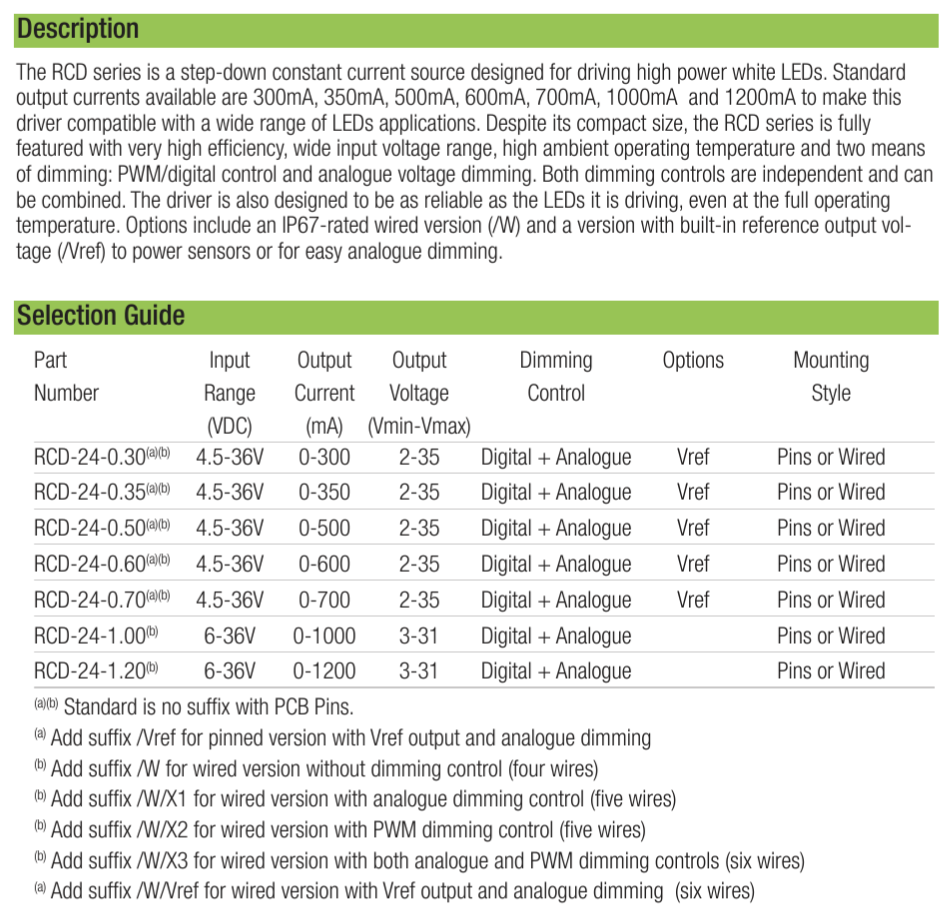
These seem great, because in addition to them being able to protect the LED they can be digitally controlled via a microcontroller, supporting both PWM, pulse width modulation, and on/off. This should hopefully fix whatever issue I was running into with the mosfet board. Under a 24V 8A power scenario, this driver will be able to set the maximum current to each LED at .7A, which maxes out each COB at 16.8W of power. This is well below their 20W threshhold, and with each COB emitting 112 Lumens per Watt, each COB should produce around 1900 Lumens. I'm thinking this will be plenty bright.
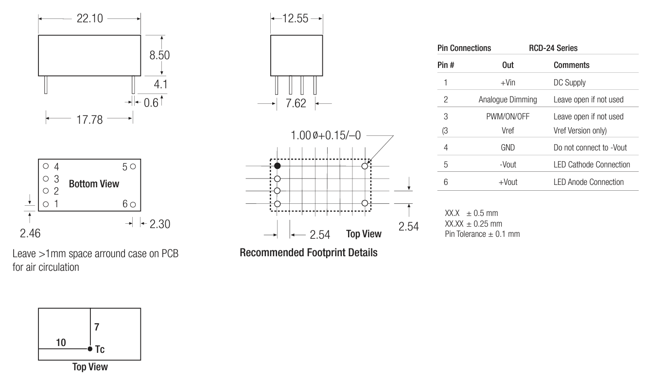
They have a pinned version so I can attach it to a PCB. For filtering purposes they recommend adding a capacitor between pin 1 and 4.
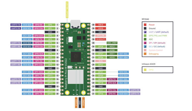
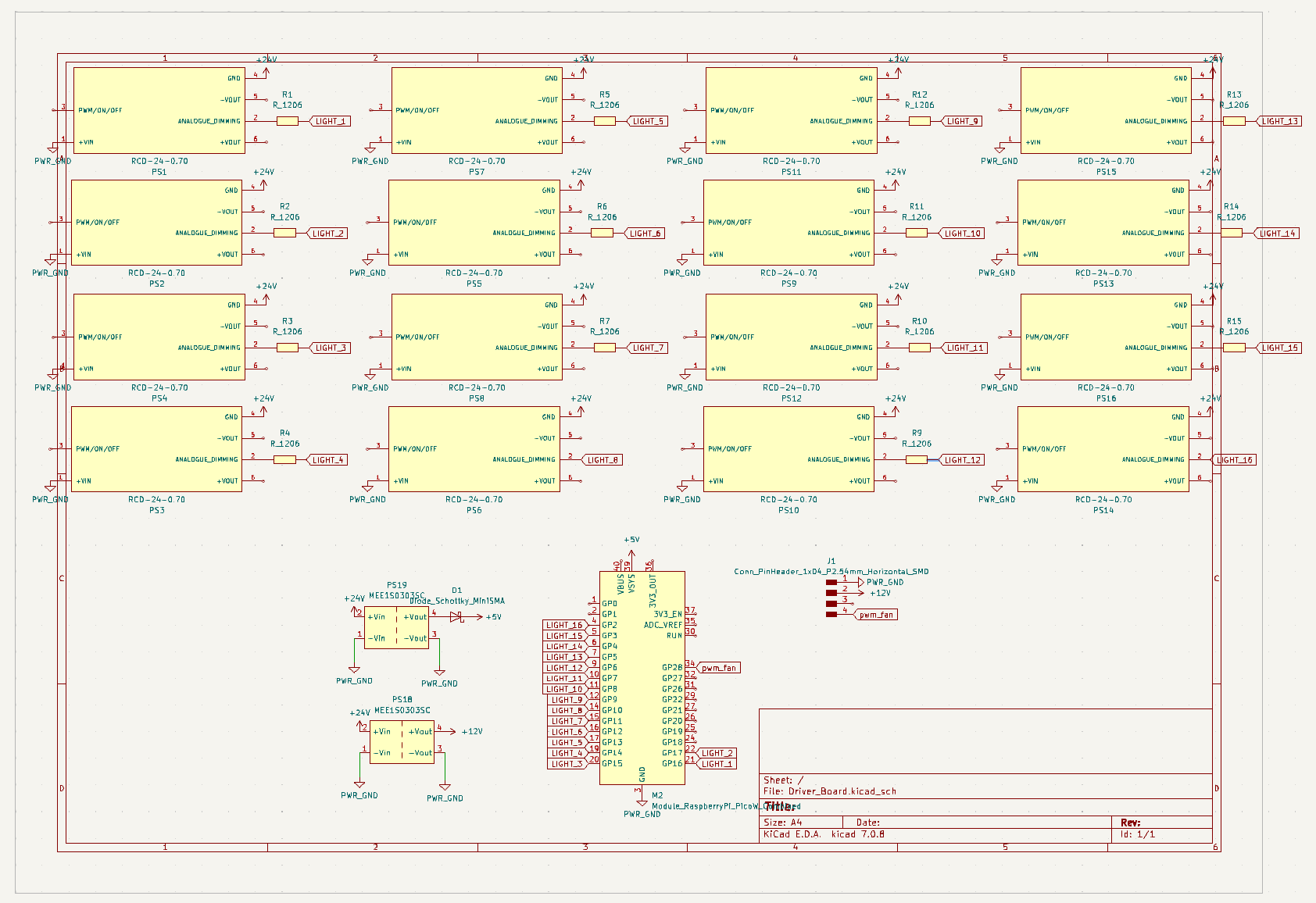
Here's a block diagram of how it would work. While the power supply would be wired in parallel to the array, the microcontroller would have a dedicated pin set aside for each of the lights. I think I will just use a Raspberry Pi PICO W RP2040 because it has enough pins, is wifi controllable, and most of its pins are PWM compatible.
Here's the pinout for the Raspberry Pico Pi W
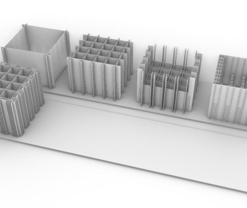
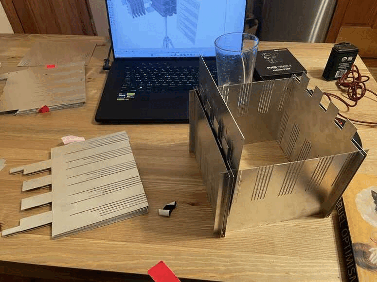
For wildcard week I transitioned to laying out the heatsink matrix and getting it cut on the fablight lasercutter. To do so, I needed to fine-tune the design and get it set up for fabrication.
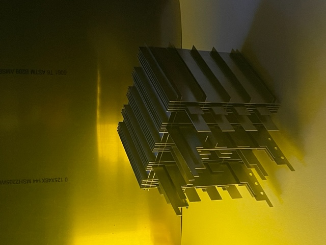
Once the design was finalized, I laid everything out flat to extract linework from, set up a .dxf file for lasercutting, and then slowly worked my way through the 6 sheets of metal. When all was said and done, the job ended up requiring 20sq.ft of 20 guage 1/32" thick aluminum.
Task 3:Fabrication
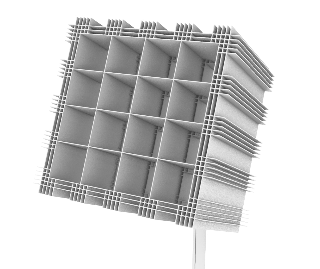
Once I had all of the pieces cut, I began to slot the pieces together. The tolerance provided by the kerf of the laser worked well, but once I got through many of the sheets, the construction process began to slow down significantly. Being cautious about the remaining time, I assembled it to the point where each light gets its own tunnel.
I added space for a computer fan in the geometry so that I can power constant airflow into the heatsink.
Here is where I have -most- of the pieces together. Good enough.
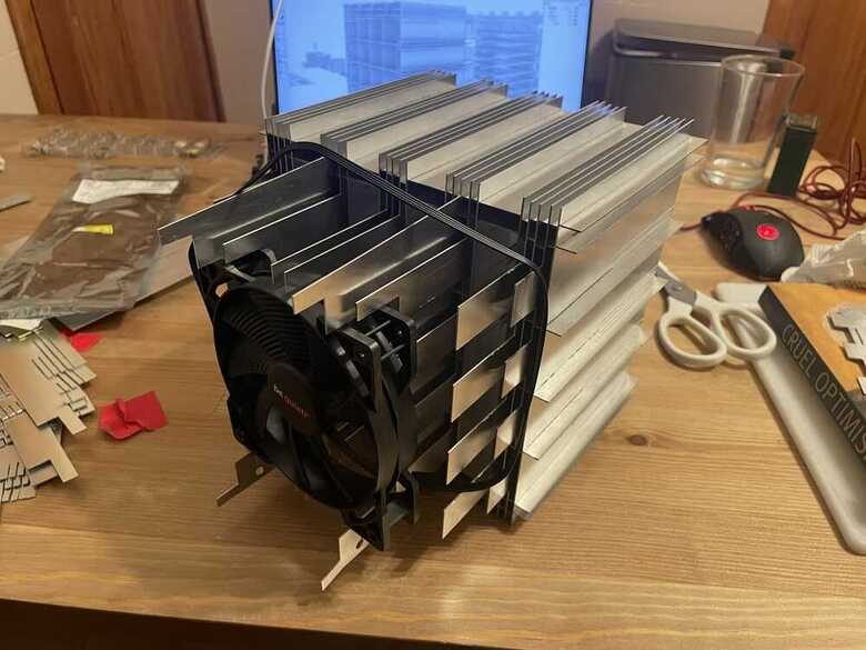
You add the lights to the heatsink with an adhesive called thermal paste. So far the paste hasn't set, I'm thinking that perhaps it never does, or rather you can buy some that does and buy some that doesn't. It sort of holds it in place while giving the component complete thermal contact with the aluminum, but the light can be removed at any time.
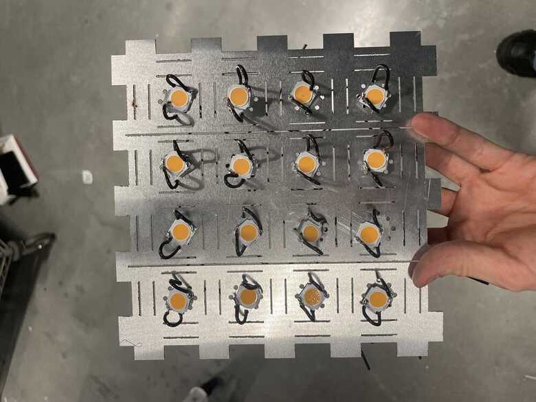
This is how the array will end up sitting!
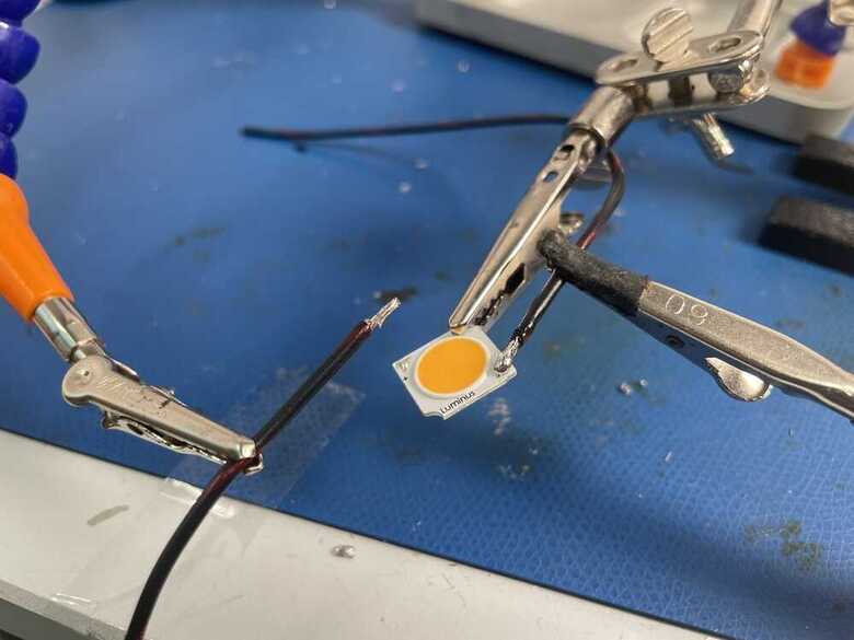
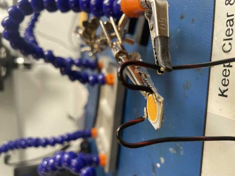
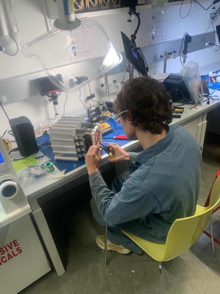
I was having issues trying to solder wires onto the COBs, but figured out that it was maybe not best to do this while the lights are attached to the heatsink. This could prevent the pads from getting hot enough to tin.
I removed the lights from the heatsink, and retried with them clamped in the air. I think this enabled them to reach a higher temperature, and was eventually able to get the solder to stick. I later found out too that the soldering iron I was using was oxidized and another one was able to solder 100x easier. So if your running face first into solder issues its maybe worth not always blaming your inexperience. Try a dif tool.
It was time to test out the COBs with the 24V 8A power supply that I got. I don't have documentation of me testing this out because I was super exhausted from finishing my studio final and cutting out all the metal a few days prior was a super pain, and patience was thin--so when I tested the lights and I couldn't get them to turn on... I was a pillar of salt. I had looked at the datasheet 100 times and had still gotten it wrong. I misinterpreted where it lists three different power scenarios as being 3 different examples for the same COB LED product, since each shared a max 20 watt capacity. But as it turned out, the form factor of this COB comes in three distinct versions, and I had bought the 36V version without even realizing it. I didn't at first think I could replace with a higher power source, because I had already bought current drivers that set the current to .7A, and this pushed a 36V power scenario over the COBs maximum wattage of 20W. And I was four days away from the final and couldn't really afford to buy another set of 16 current drivers... they were by far the most expensive part of this project with 16 at like $16 a piece. I was crushed >.<
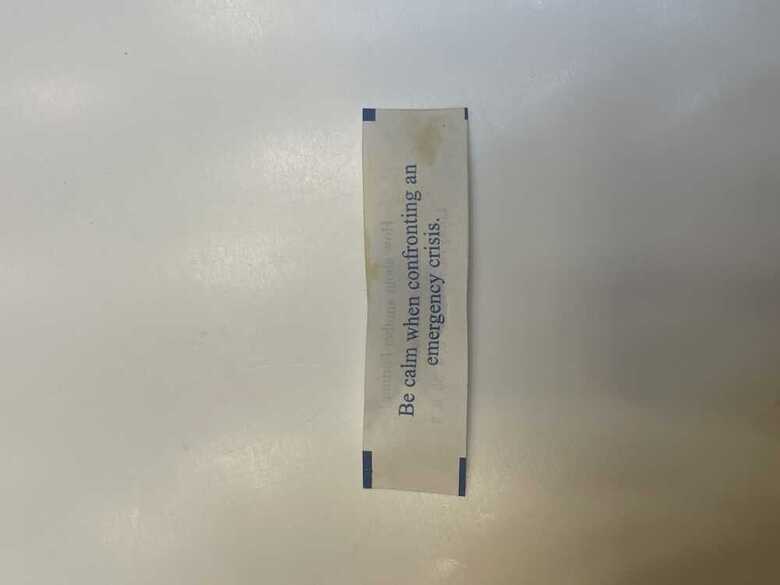
But then I got an auspicious sign from a fortune cookie.
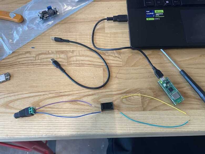
My friend Skye offered to give me some of her lower power LEDs so that I could at least put together a proof of concept version of the project. Disappointing but had to pivot. Skyes lights were 5V 3W maximum. I had to figure out another way to power them. I ran to microcenter and got 4 of these power supplies so that I could potentially split my circuit into 4, keep adequate amerage, and regulate the voltage.
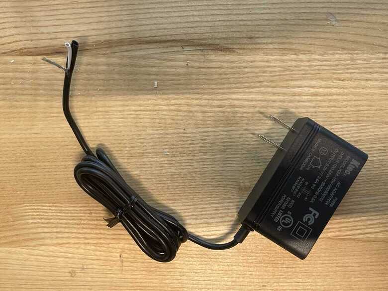
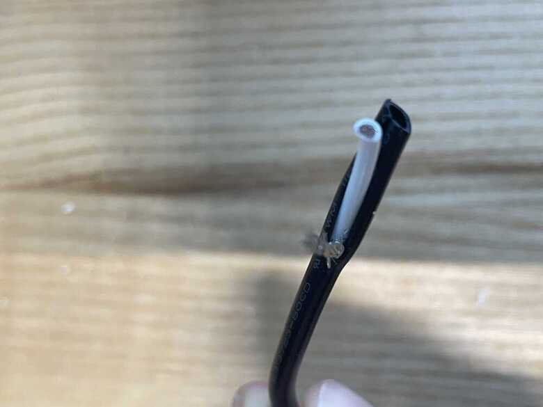
They didn't have an adequate adapter for USB-C... so I opened up the wire. Didn't know this was allowed, but it is.
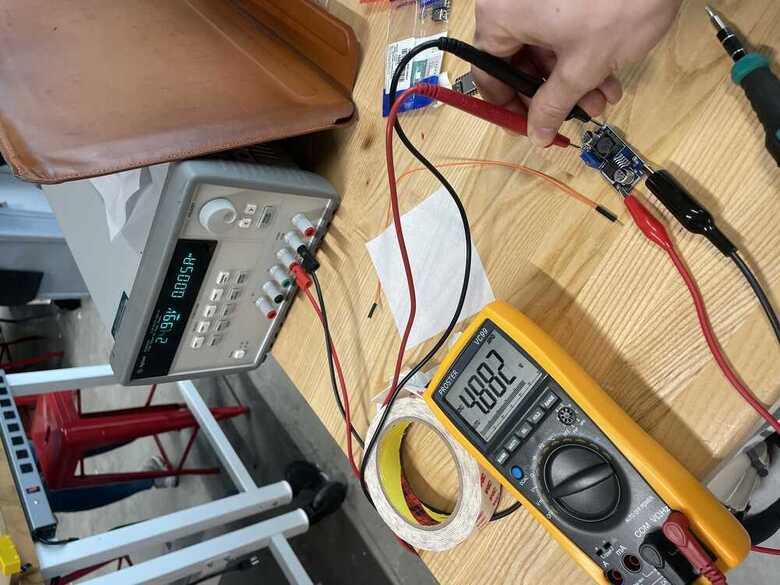
I had to figure out which of these was ground, and which was power. I used a multimeter to check continuity.
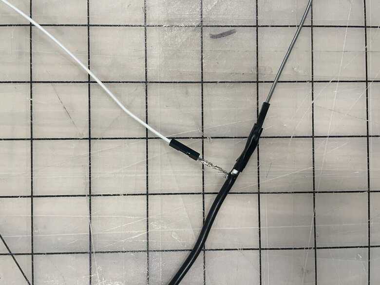
A quick solder for a test! I still needed to see whether or not the current drivers were bunk. It was an anxious test.
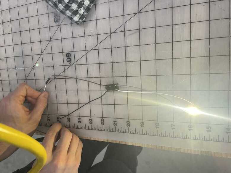
Let there be light! At least the drivers worked. I figured at least now I can move forward with trying out different arduino functions on the low powered light through the current driver.
This is the dumbest electronic in the world.
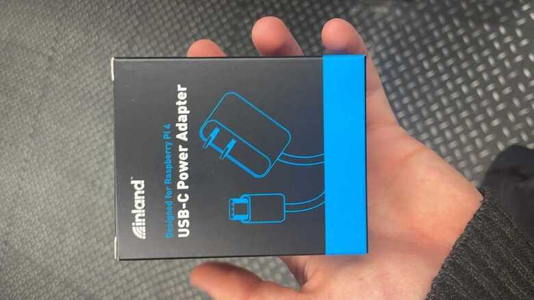
This is me trying to get the PWM to work. You can see the climb from 0-255 on the serial monitor. I just started this process by asking ChatGPT how to do it then made some alterations to adapt it to my use case. This ended up leading to a PWM code that can call individual pins which I used in my final here. This also led to a fruitful conversation with TA Quentin where he explained that PWM is essentially a way of programmatically controlling the current. When the light is off, there is no current. When it's on, there is all the current. The way PWM flickers the light at highspeed, creates a ratio from which you can deliver less current, and in effect dim the light. This was actually the solution to my once-thought driver problem. If I could get a beefier power supply--to the order of 36V 8A--then I could drop the current using PWM, keep the lights at a safe operational capacity, and have the extra voltage around to get the lights to actually turn on. In seconds I was on amazon buying a 36V 10A AC/DC Converter, I had to at least attempt--and if it still didn't work at least I'd have these lame lights.
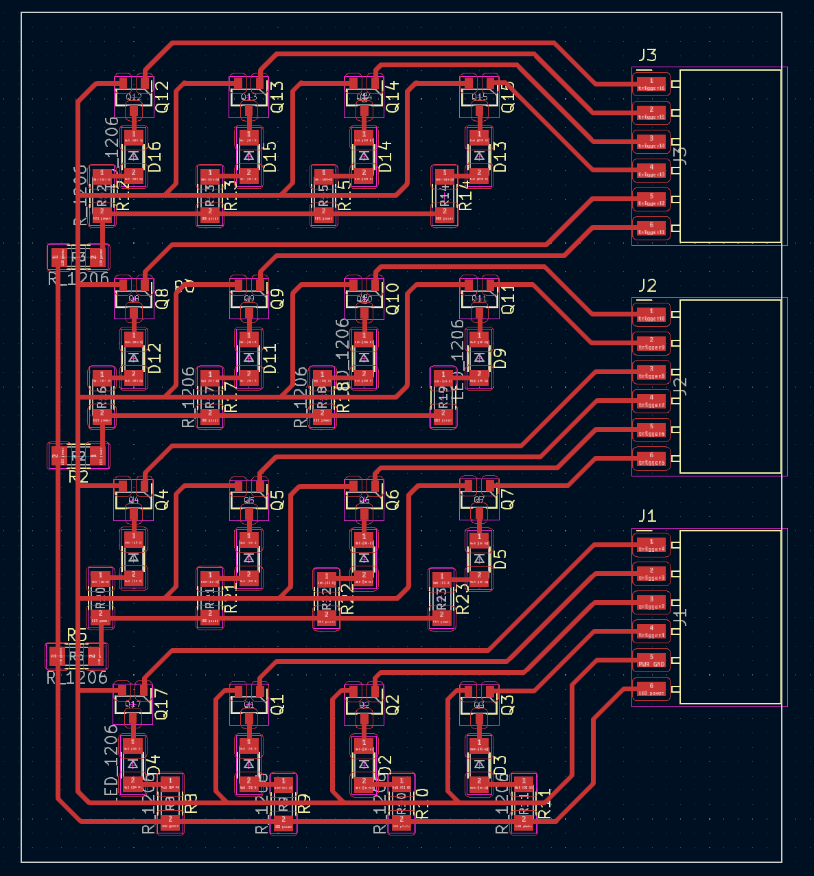
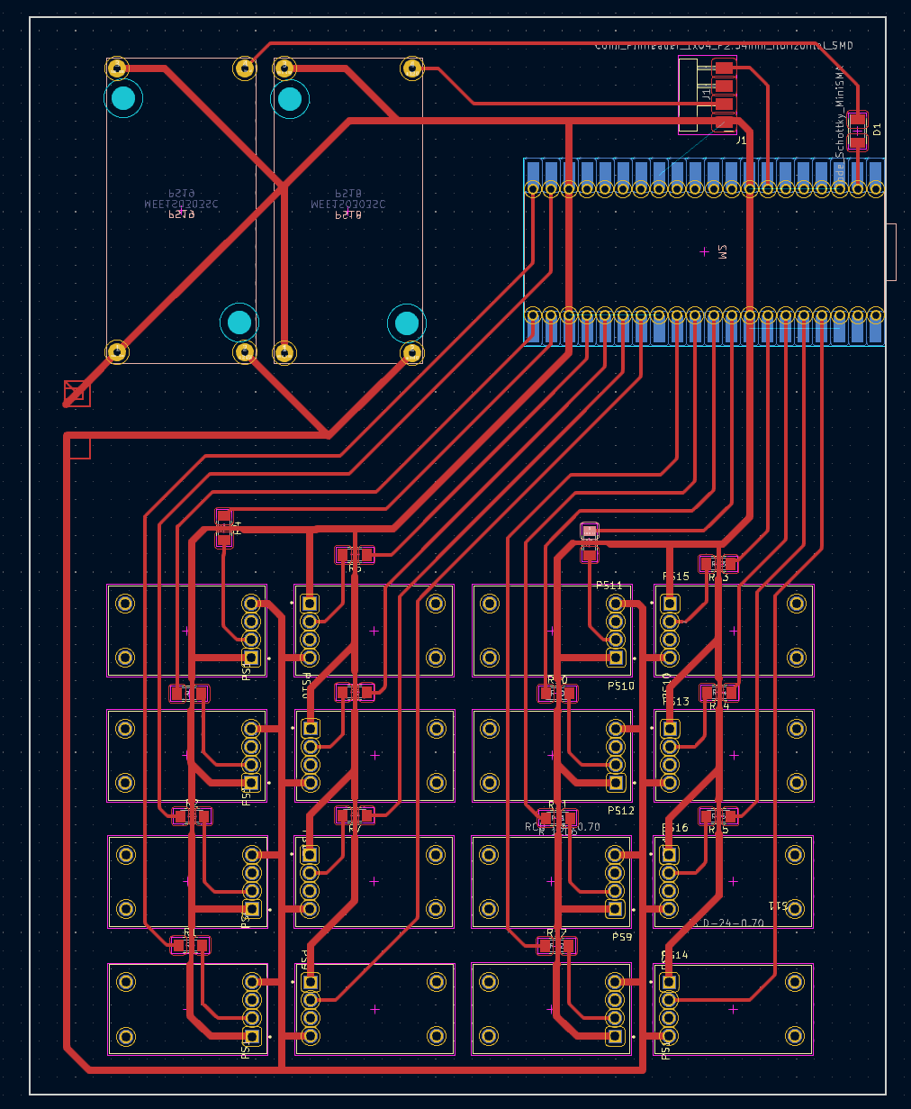
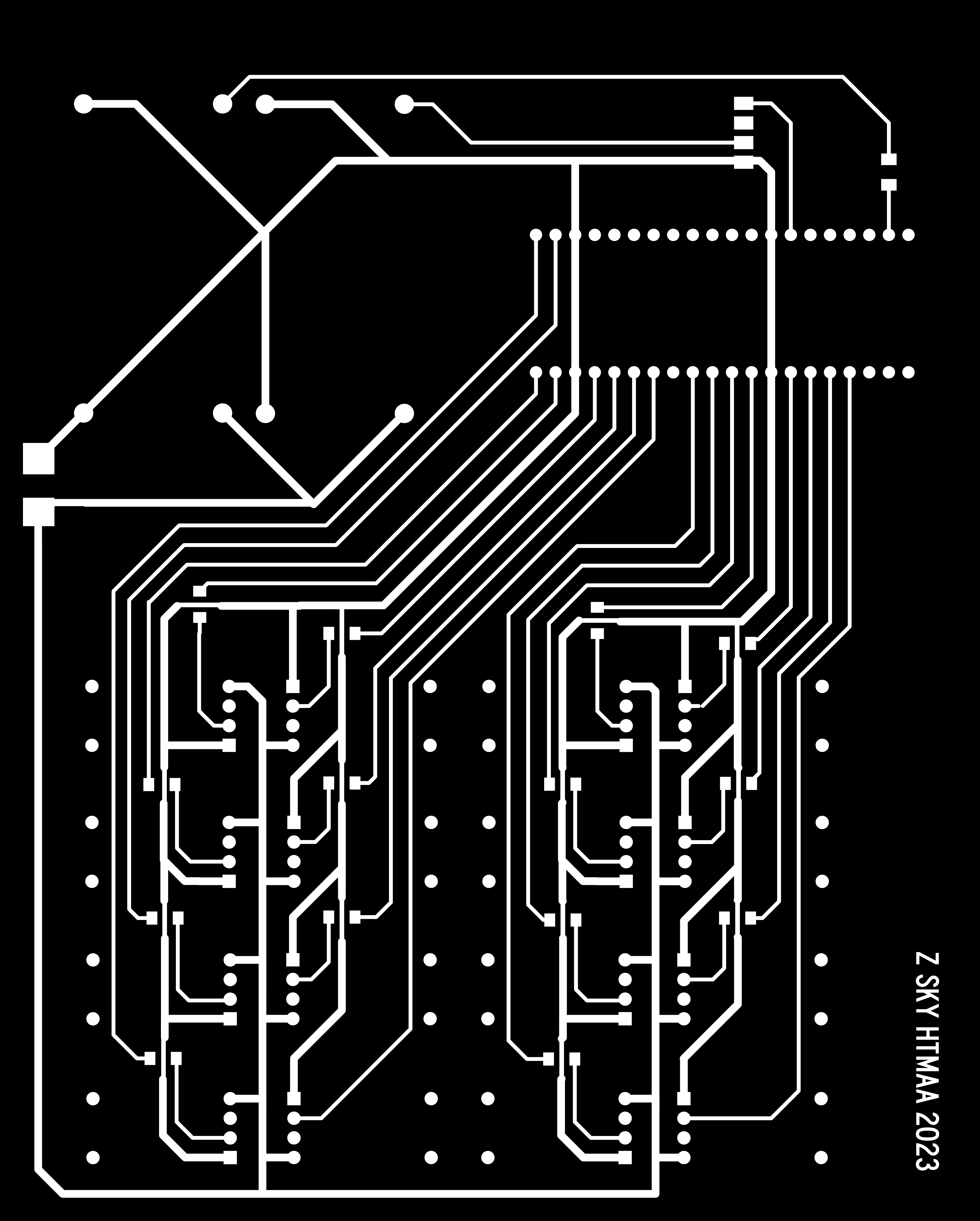
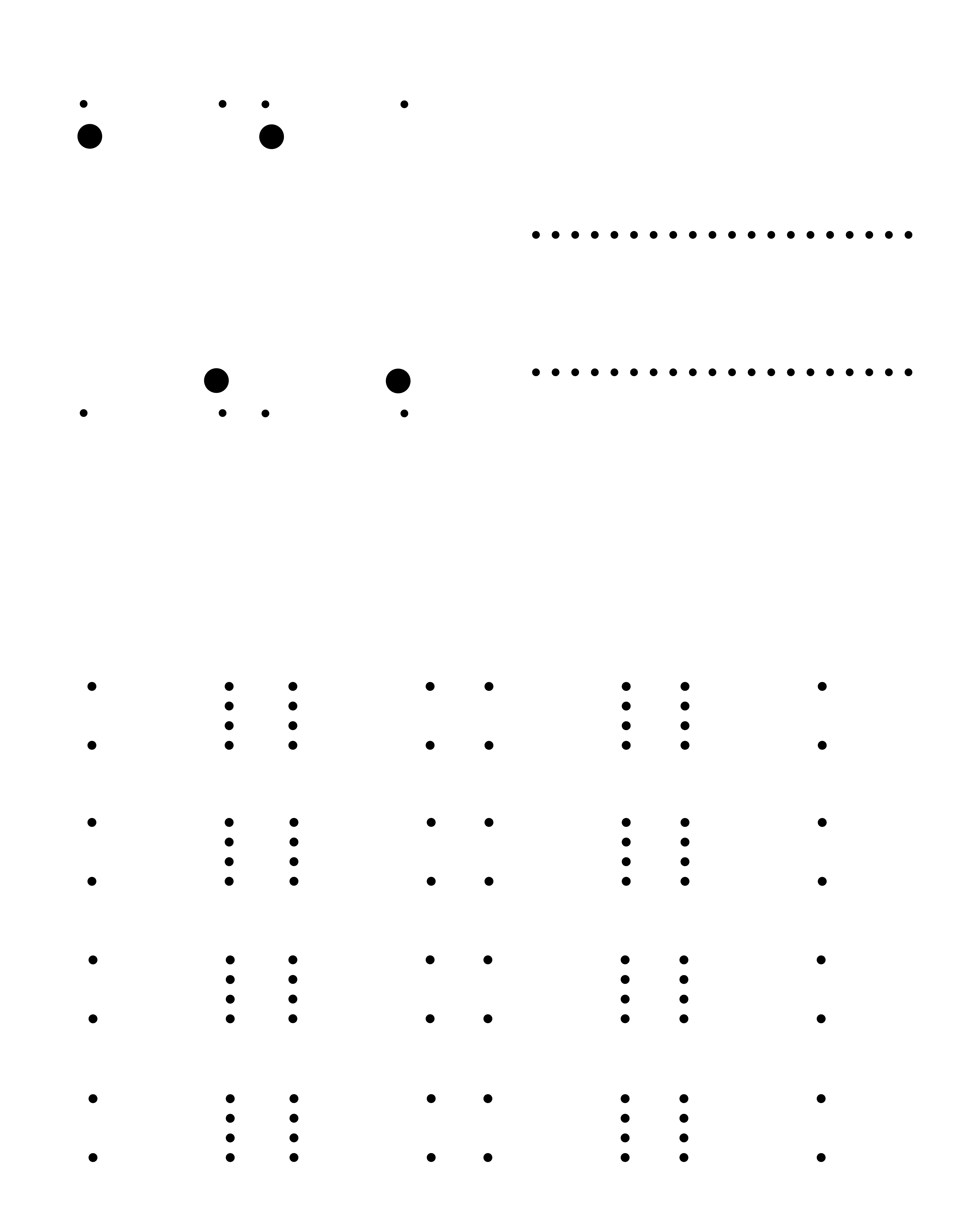
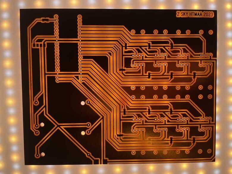
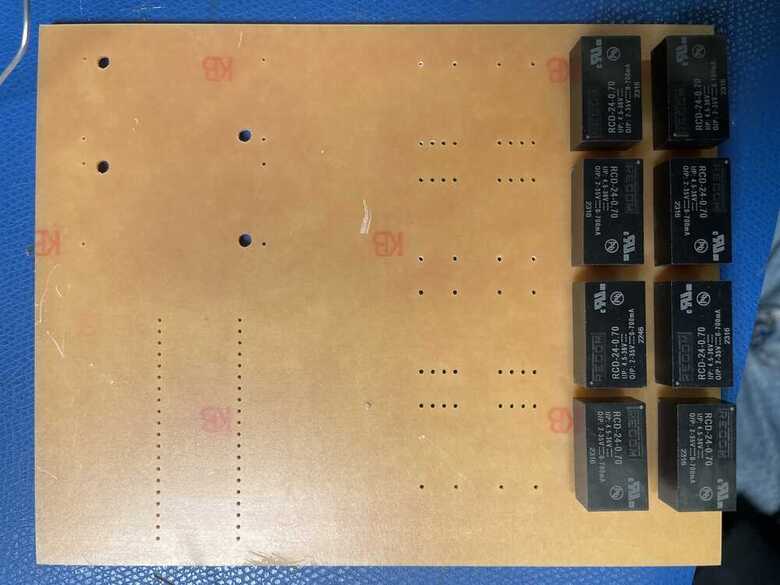
I needed to put together my PCB yet, so I put together a schematic that included my pico W, a four pin connector for the computer fan, two DCDC converters--one to bring the 36V power source down to 5V for my microcontrollers consumption, another to bring it down to 12V for the computer fans consumption--and then there were the 16 current drivers. I made it a double-sided board and plotted a drill file because I needed the pins to be accessible to later solder on the wires. This strategy also had the added benefit of keeping the electronics cool in addition to the lights--its like a fan sandwich. PS--make sure you invert your drill files so that the holes are black for mods. I made the traces for ground and power 1mm--double what I used for the PWM traces--and as it turns out this is still not nearly enough for 10A to run through so there were some power issues that I later ran into.
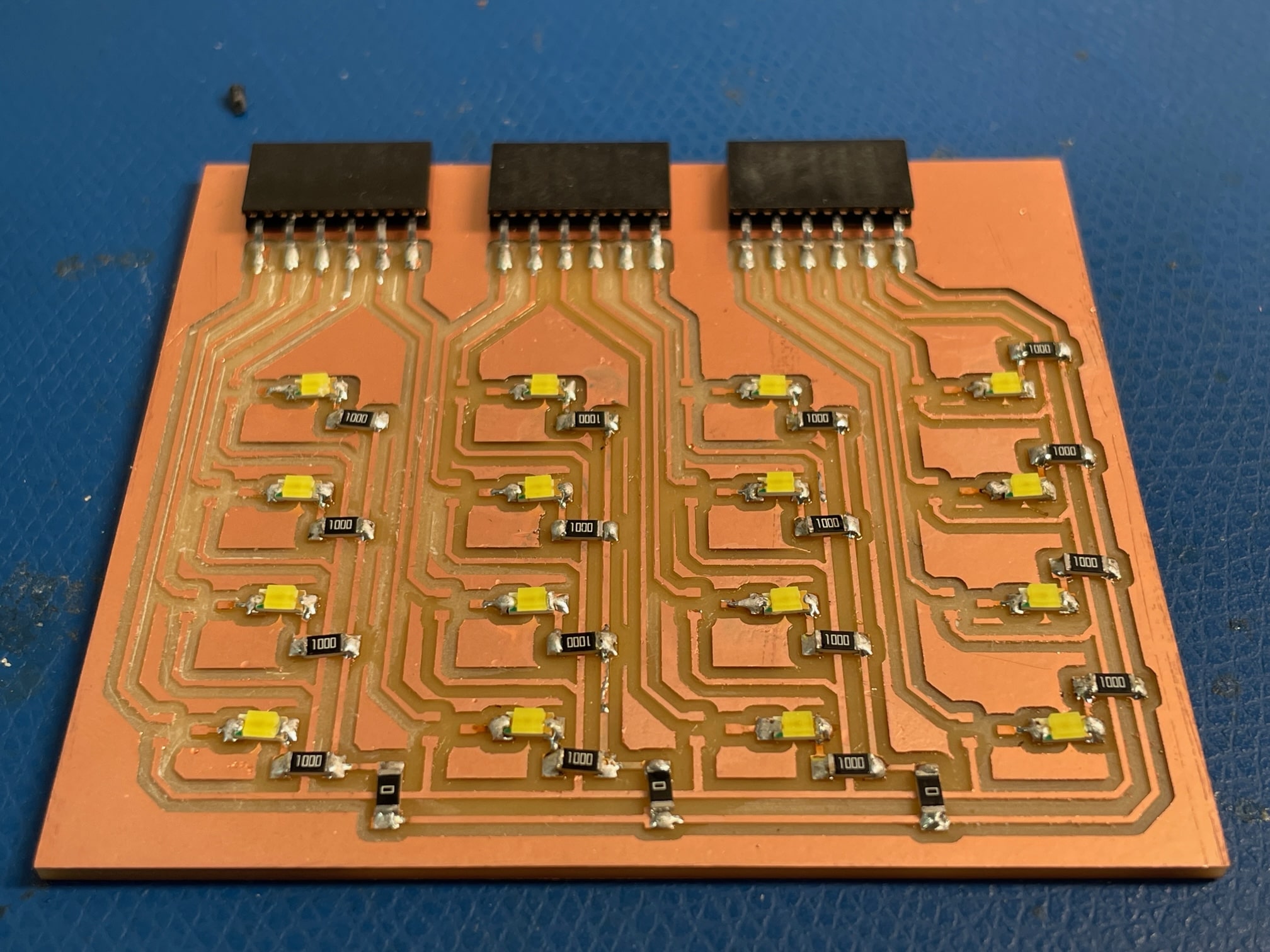
Milled the board, the .7mm pins fell right into the 1mm drill holes.
Before soldering on the DCDC converters I used a power supply and a multimeter to set the DCDC converters to their respective output voltages, 5 and 12.
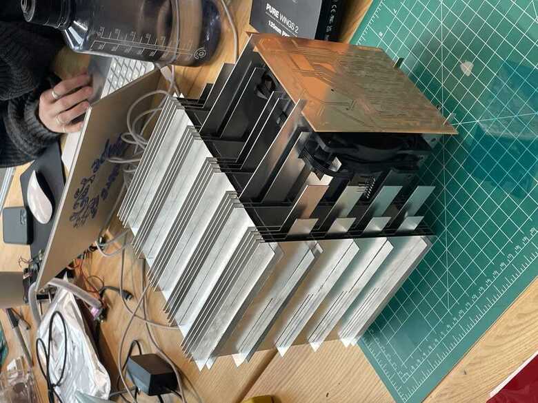
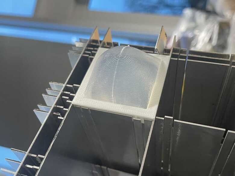
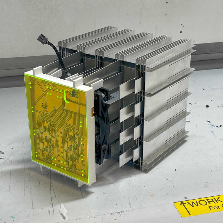
The PCB fits to sit inside this back part of this aluminum matrix, on the otherside of the fan. I wanted it to be visible from the outside.
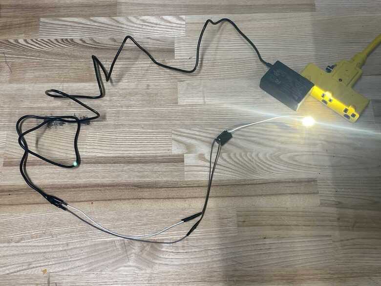
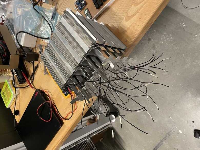
The new power supply wasn't going to arrive until monday night, but I just went ahead and wire soldered all of my COBs down to the heatsink plate. Worse case scenario I could just rip them off and rewire everything for the lower-power lights. I initially tried soldering the wires on as shown in the top image, but once I threaded them through the baseplate and set the COBs into the thermal paste, they would move around a lot and remove themselves from the base plate. This could be a potential failure mode, so the solution I came up with was to overtravel past the COBs with the wires and have them do a U-turn because being soldered on. This way, they would be trying to push the COBs down instead of trying to pull them up. It wasn't perfect, but it worked much better
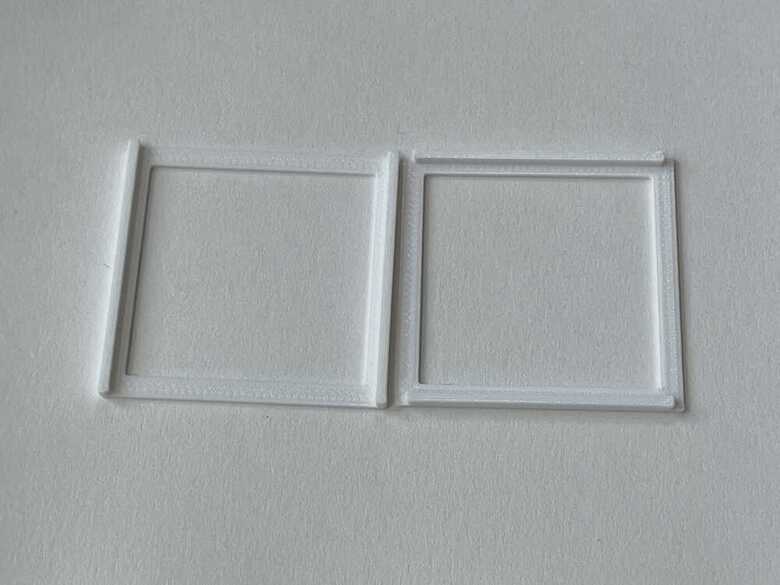
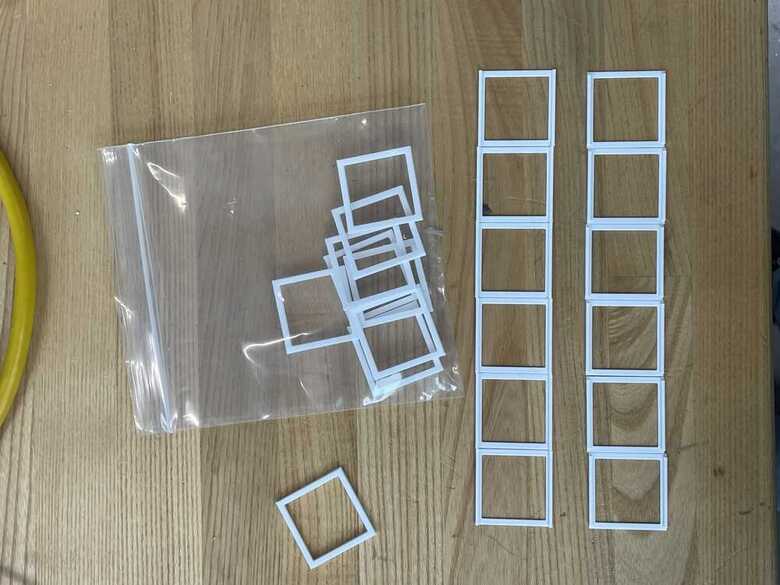
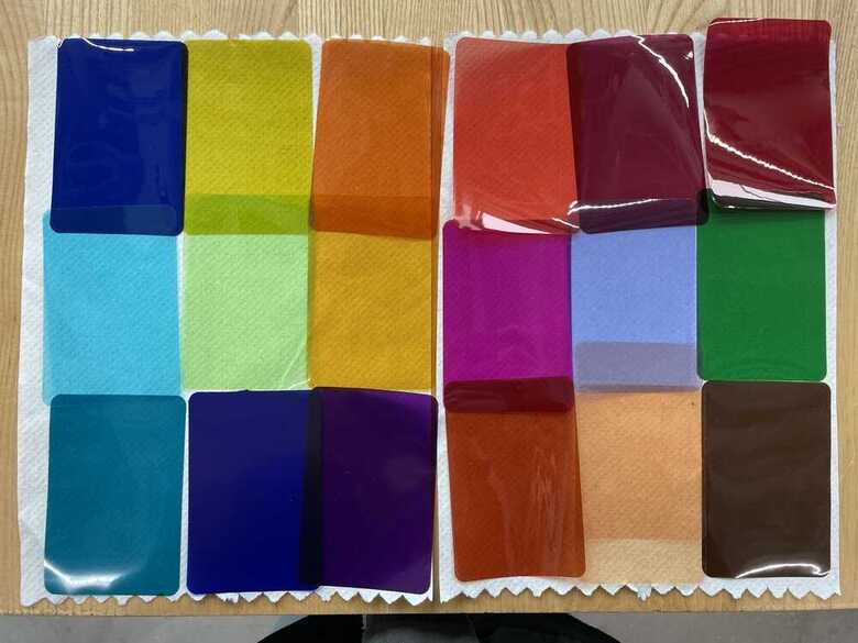
While I waited for the new power supply to arrive in the mail, I printed out a series of frames that could hold light-filtering gels. They're sized to fit inside of the aluminum matrix, so that you can't see them from the outside but rather you just see that colored light is emitting. I didn't really find any color COB options, and I'm glad I didn't because any additional wiring would've been a nightmare.
I made one of the frames hold a cast of translucent SortaClear. This was mainly motivated by the requirement to include casting, but it is an interesting prototype idea for having some of the lights with color, and others with diffusion, and having these place formally within two seperate systems so that color can be diffuse or not diffuse, and vice versa.
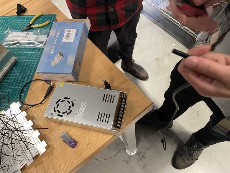
Ok so power supply arrives and there is one unexpected problem--there is no wall outlet? How the hell am I supposed to plug this into the wall. I talked to Quentin and Leo about it and they said that the screen plates along the side include the input power, and that I would need to--VERY CAREFULLY--get bare wires underneath those screw plates. We took my old 24V power supply cord, cut its open, and then used a multimeter to check--4 times over--which wire was live, which was ground, and which was neutral. All needed to be screwed into the correct part of the power supply, or it could be dangerous and I could blow a fuse. Also had to be super cautious that there was never any bare wire that could be touched while the power supply was plugged in, and that the little plastic screen above the screws was always pulled down when things were plugged in. 36V 10A could be lethal, which made me nervous, but I just made sure I had the TAs walk me through and triple check every step of that process. And once everything was wired, it was much safer, mostly just a question of plugging it in.
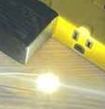
But it worked! Project saved!
The baseplate just slides into the back-fins of the aluminum matrix. It was a pain with all the wires getting caught and took a solid hour of tedious focus and troubleshooting but ended up falling into place.
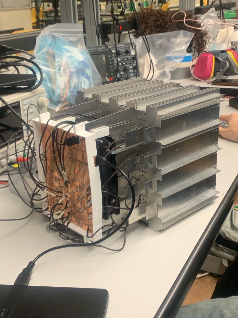
I made a case for the PCB board to keep everything protected, including some guide holes for the wires to enter in, but unfortunately I ended up running into a time crunch when the Harvard Sections lab was closing at midnight, and I had about 45 minutes to finish soldering everything. The plate was too much of an obstruction to work around in a time crunch, so I removed it.
Not as pretty. Se la Vie. We had to pack up all of our belongings and clean up our mess in 10 minutes. Then we headed over to the electrical engineering labs at MIT to stay up late and hopefully get out projects to work...
Task 4: Getting it to Work
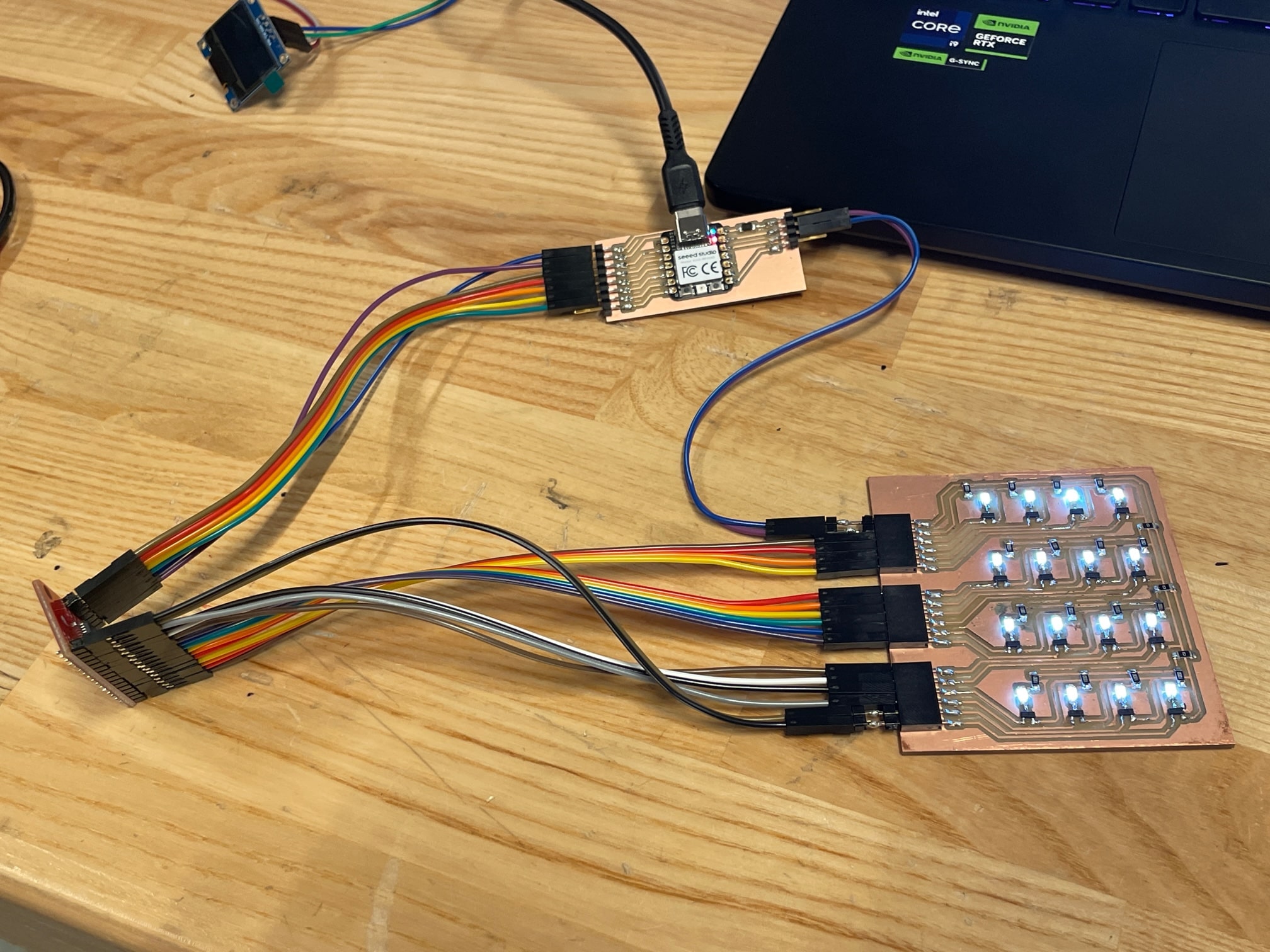
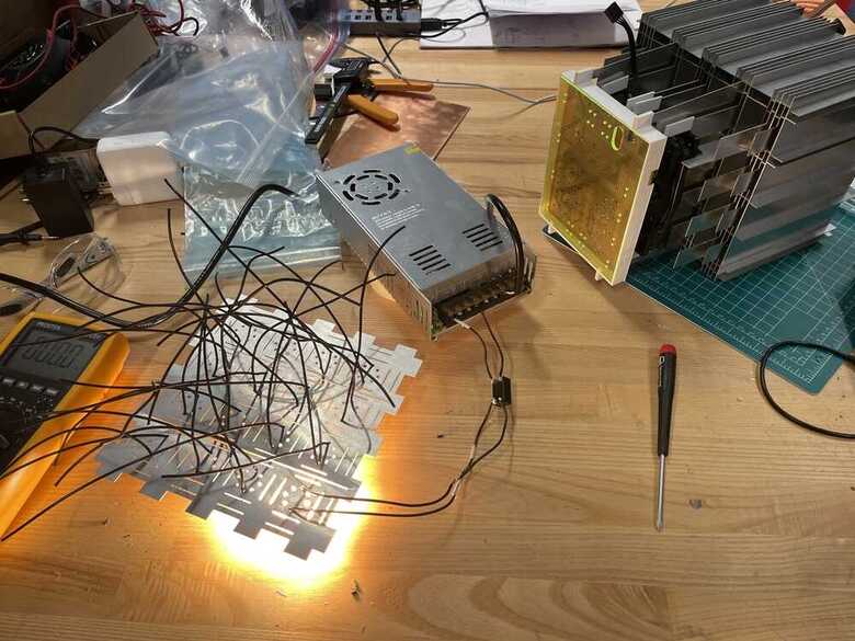
Everything is soldered together, ready to go, I go to plug it in and..... RIP. The lights would turn on, and then crash about a second later. The lights on the DCDC converters would stay on even after the lights crashed off, meaning the board was still getting power but the lights gave up. Now that I was at the EE lab I asked Anthony what he thought and he said my traces are much too small for that much current, and that when I turn it on the board gets overwhelmed by the current and its voltage drops. We tested this on the oscilliscope but weren't able to witness a voltage drop. This didn't bode well, but Leo and I were talking and figured we should try to use PICO to program most of the lights off and see what happens then. Once I started to program the lights, things started to come together--the lights on remained on.
Once I started using the PWM to control the current, I was able to keep all the lights on, minus the two that never came on. Not sure why these ones gave up, the soldering and wiring looked fine and there was this weird coincidence where these two lights were the only two lights attached to pins on the otherside of the PICO W.
I placed my gels inside and coordinate the addresses of the pins to the lights with color gel over them (I didn't want to put color into every gridspace). Once I got the wireless webserving to work, I called it a day, and went home to get a few hours of sleep before the presentation.
Task 5: Having Fun
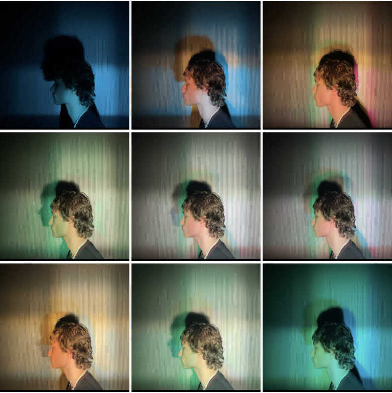
There were so many parts of this process that left me less than confident in my ability to pull it off, but the end outcome ended up being exactly what I was going for. Super thrilled. If I were to do it over again--and I might--I would change just about every part of the design in someway. But that's sort of the point. This photo shows how the grid spacing produces different shadow color displacements.
Presentation, Test, Reception
Nothing more rewarding than seeing people have fun with it!
.jpg)