Try and come up with final?
I didn't really know what I wanted to do yet. I was playing around with a few ideas, and a number of them included LED matrixes. I have zero electronics or coding experience so LEDs seemed like a good balance between feasible and new. Plus, I love lighting. I've design some stuff with lights before, but don't have very much control over the light component itself, mainly having just worked on its container.
My thoughts still weren't nearly concrete enough to model something. I'm in architecture school so I have to model all the time--and the model is really just a reflection of thoughts you have around part/whole relationships and that takes time to develop if the designs going to be any good. I decide that since I was leaning toward LEDs and matrixes, I would just go ahead an design a parametric press-fit grid with kerf inclusion. I didn't know how many grid spaces I'd end up wanting in the matrix, or how big I'd want the grid holes to be, or what material thickness I'd be using, but I figured all of these variables could be put into the equation and adjusted for later when I had a better idea of what my needs were going to be.
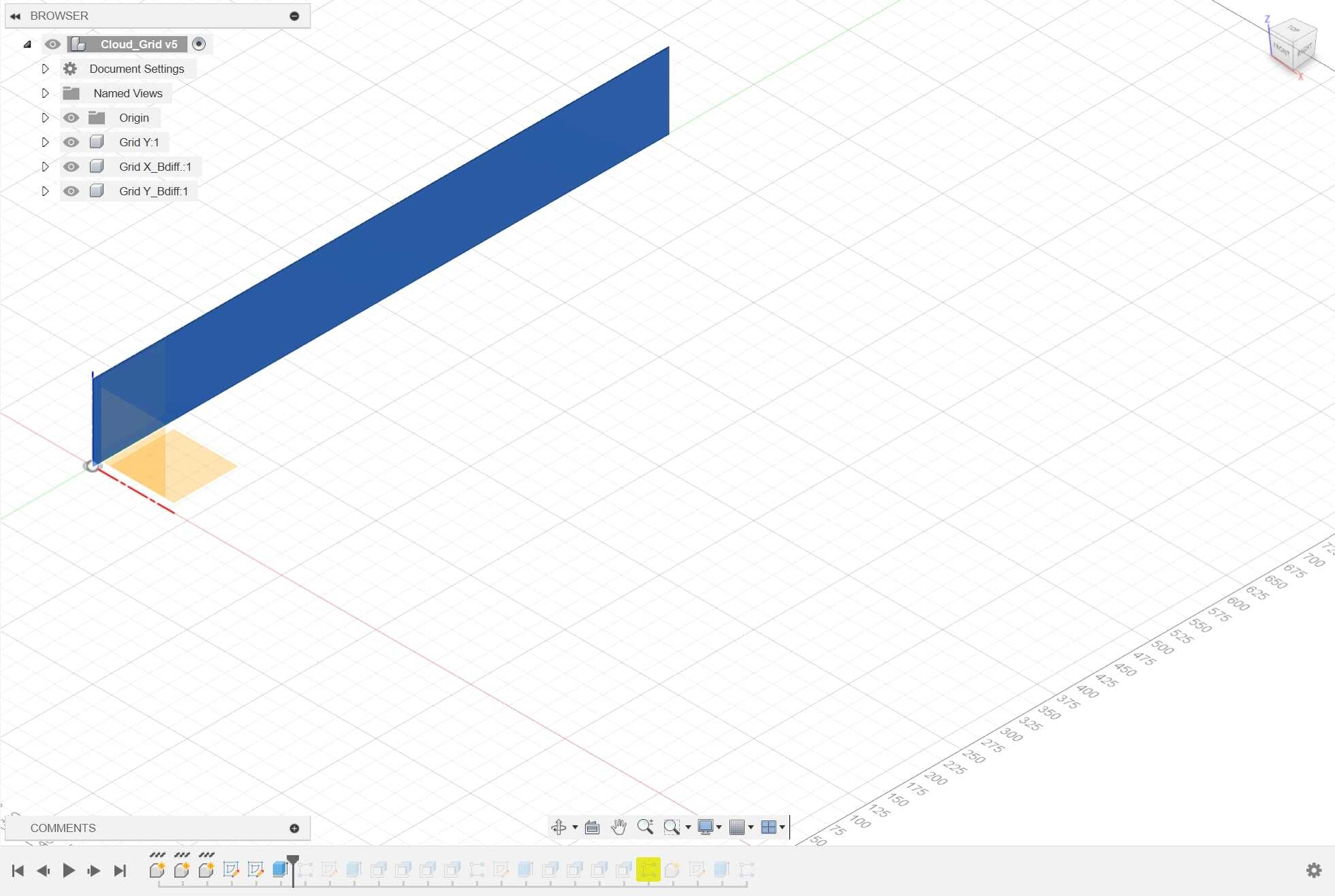
I downloaded fusion 360 for the parametrics. I've never actually modelled in anything outside of Rhino bc I've gotten so fast at that, but admittedly there are a number of annoyances that a parametric workflow would fix, so I was eager to check it out. I first started by drawing a rectangle, and extruding it into a rectangular prism. I was originally thinking that the LED array would contain enough LEDs to produce a screen--it hadn't yet occurred to me how much soldering this would entail.
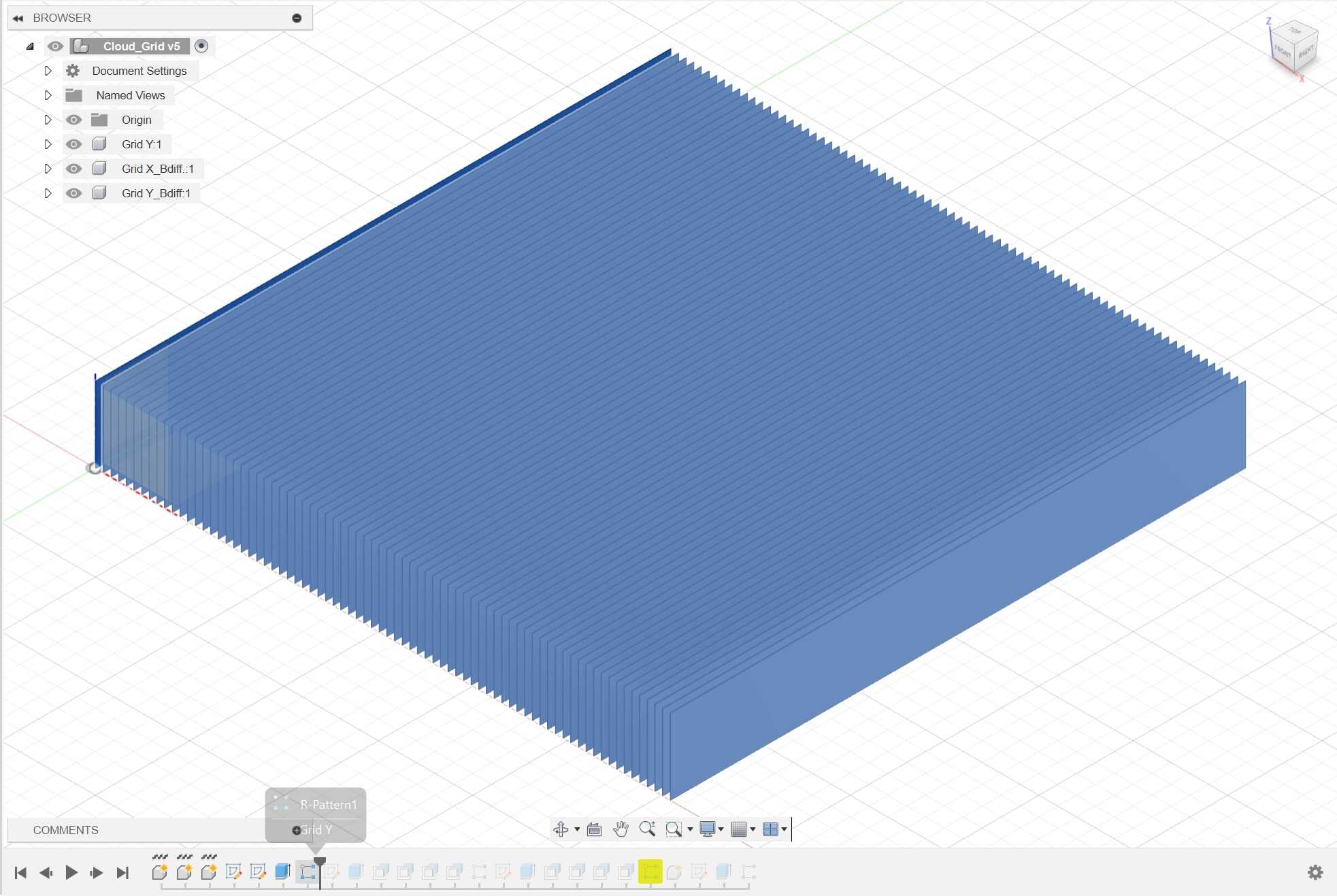
Once I had that, I arrayed it enough times to equate length and width--making a square.
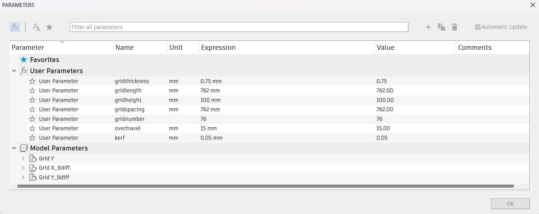
These are the variables I was working with. They're mostly self explanitory--you can change the thickness of the stock, it's height, length. The overtravel part is less intuitive, it basically comes about as a product of the way array functions work. The kerf variable is there to accommodate for materials tolerances in the press-fit joints.

In order to make the press-fit joints, I needed to array the boolean-negative of those slots. So I made a bunch of stick-like rectangular prisms, with equal parts length and width, and with a height that is 1/2 the height of the stock it is booleaning into. I arrayed one set of these on the top half of the grid, and another on the bottom half of the grid--each the bottom array grouping being used to cut a cavity from the xy stock, and the top array grouping being used to cut a cavity from the yx stock.

Here you can see how they overlay.
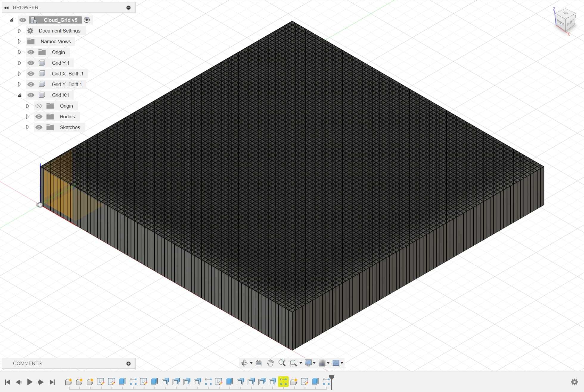
And here is how all the systems sit on top of eachother. It's a perfect square, of any grid count, with any thickness of stock, with any necessary tolerance compensation. And no, I didn't end up actually using this model for my final lol. I ended up making something much more idiosyncratic and complicated in rhino later in the semester out of time necessity. But I still recognize how useful the parametrics are... I can imagine myself using this file for whatever other box grid fabrication I'll run into in the future. If you ever want to make a bookshelve or shoerack or whatever else, check it.