Individual Assignment Prompt:
Cut something on the vinylcutter design, lasercut, and document a parametric construction kit, accounting for the lasercutter kerf, which can be assembled in multiple ways, and for extra credit include elements that aren't flat.
Part 1: Use the Vinylcutter
For this assignment I choose to use the Zund as my vinylcutter. The Zund is a pretty assessible piece of equipment at Harvard's Graduate School of Design, and I've used it a number of times for various model making tasks. Typically, the Zund is used to cut paper, foam, or plastic sheets, but once I had heard a rumor that the Zund was able to cut 1/8" aluminum, so I decided to get to the bottom of how that can be done.
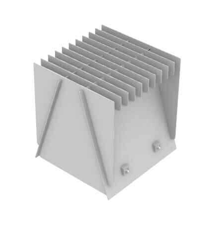
I started by altering a design for a stool that I had previous made in wood to work for an 1/8" aluminum stock. There were many things to consider as I designed for this material.
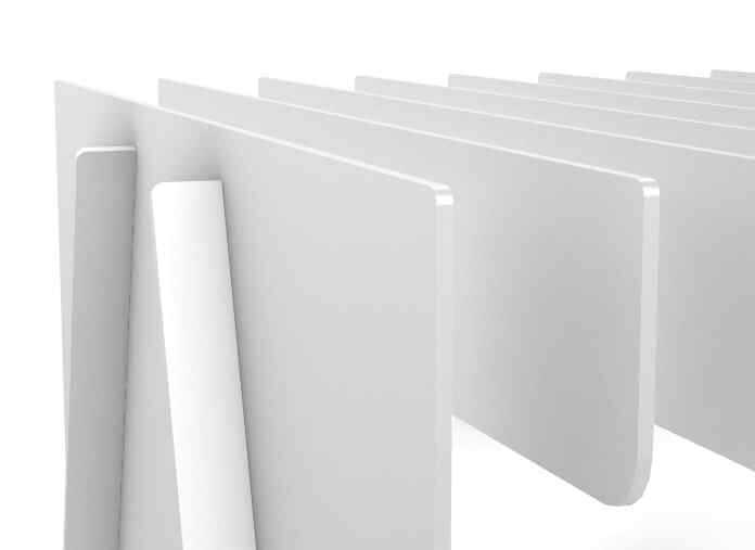
The first major consideration was that aluminum would produce a very sharp edge when cut on the zund. I had to fillet each corner to account for this. This ended up being a design opportunity, since I used fillets of differing radii to communate which edges were related to one another.
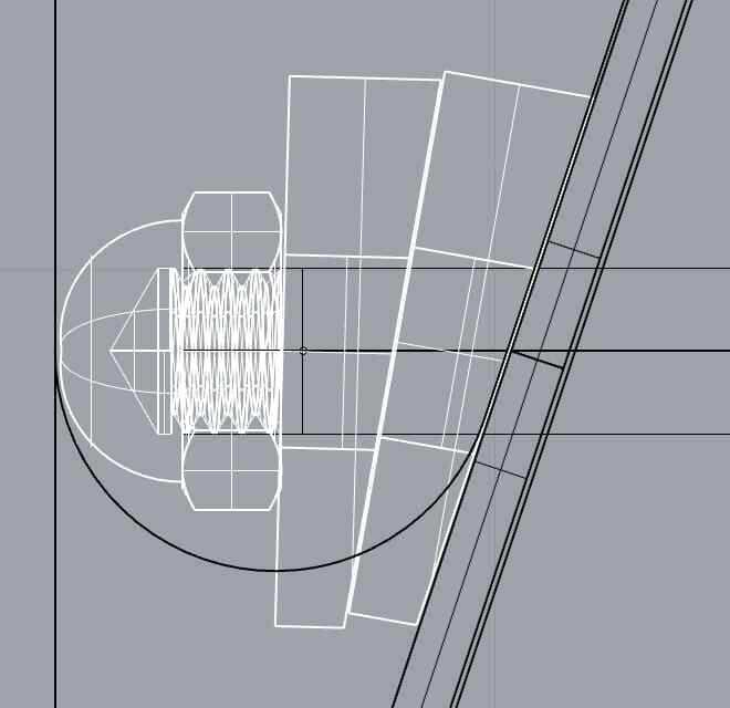
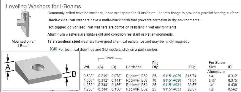
I needed to update the hardware detail in the design to corroborate the aluminum's industrial aesthetic. This detail had to be much more precise than in the wooden version, so I had to rely on McMaster-Carr's publically available 3D asset library. You can test your design using the 3d models they have of their products on their website, and then order something you know will be to spec when it arrives.
I knew I needed to source aluminum hardware, not just for aesthetics but because stainless steel hardware would cause galvanic corrosion to occur overtime.
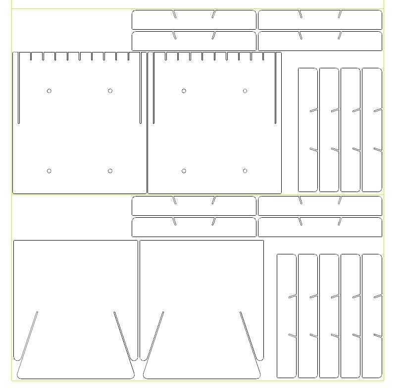
After settling on the design I laid each unit out to see how they would fit across two 2x4' aluminum sheets. I added an additional offset for each of the slot connections to include an assembly tolerance. In hindsight I overshot these tolerances a bit ¯\_(ツ)_/¯. Without tolerance, the slots are the thickness of the material, which is 1/8". I made each slot 5/32" thick, which was super overkill, considering that's like a 25% tolerance. I think the ideal tolerance would be closer to 5%.
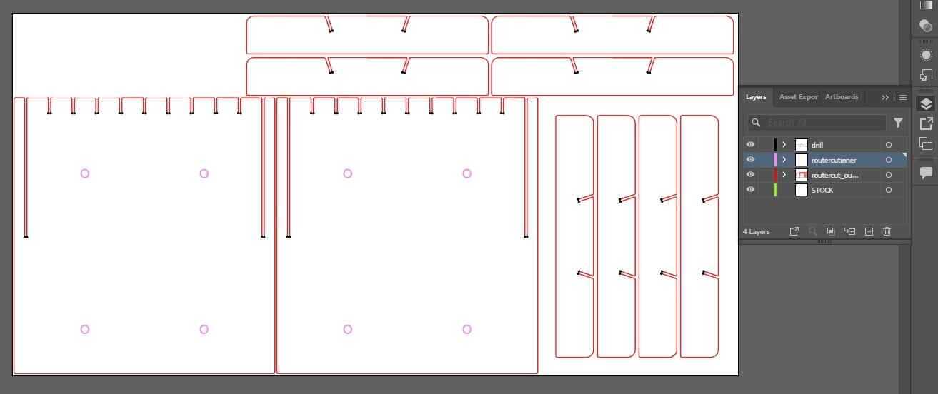
The Zund at our school only reads illustrator files, so each of these 2x4' layouts need to be exported as a .ai or .dwg or .svg and brought into adobe illustrator. You can see the drawing split into four different layers. There is one for the stock size (24x48"). There is one for "inner cut" which is necessary if you have geometry being cut out of pieces that will eventually be cut out themselves, since a piece is subject to movement if its being machined without the surrounding stock connected, providing support. The innermost nested cut layers always get cut first, followed by the next innermost cut, and each need their own layer in illustrator for the Zund to be able to do this. Lastly, there is a "drill layer", which essentially is to remove the fillet left behind by the circular drill bit when producing interior corners. This is called "dogboning" in machining (because it looks like a dogbone), and allows you to maintain proper tolerances when using slot joints like in this design.
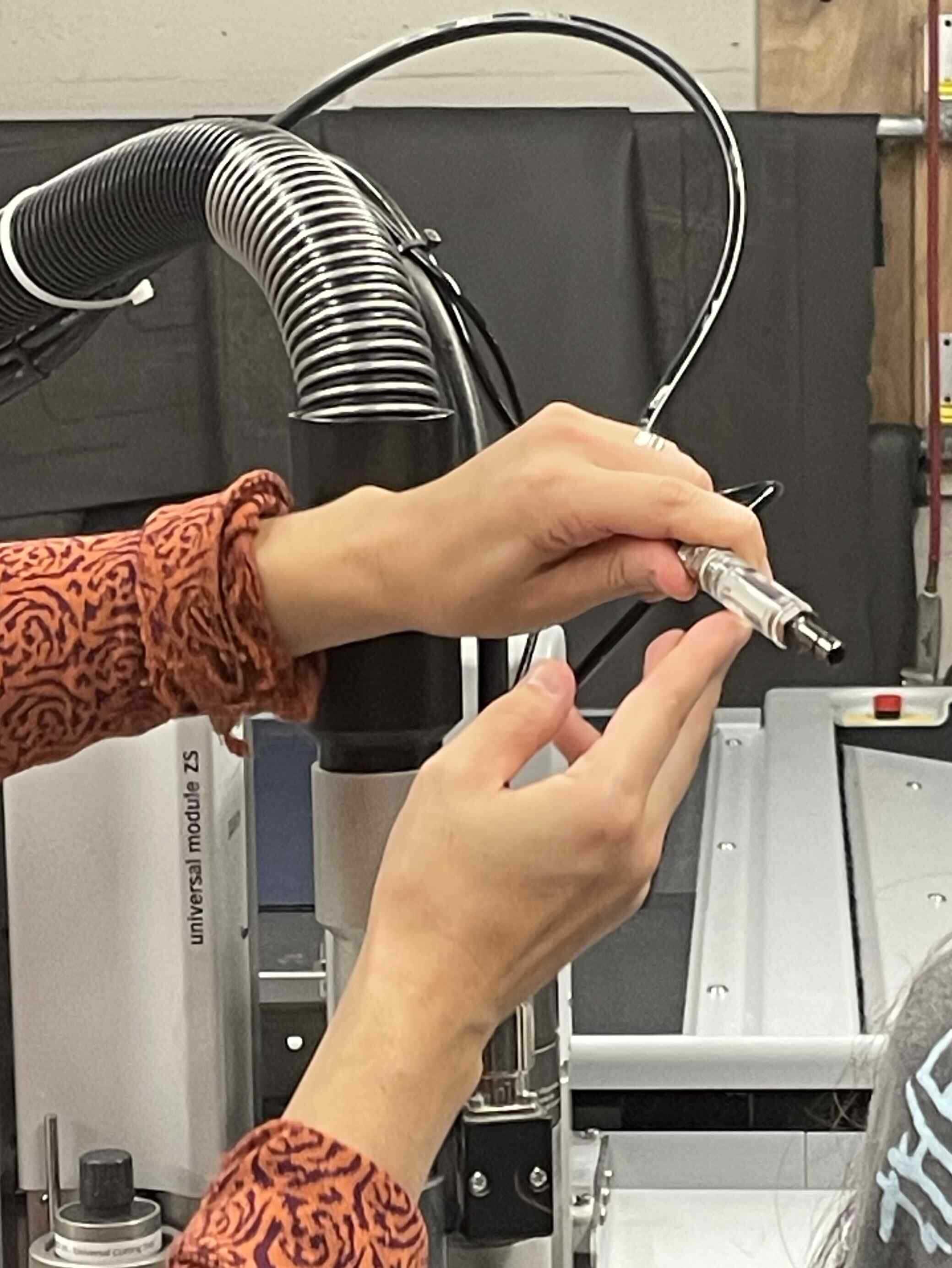
When making cuts or engraving passes into aluminum, the Zund needs to used a constant stream of oil lubricant on the bit or else it will break off. So before sending the file through we had to refill the oil reservoir and pump a new lines-worth of oil through to push out any air bubbles that might have found their way in there.
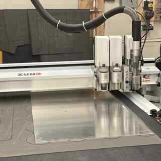
There also needs to be a grip-seal mat laid down under the material to help prevent it from moving and protect the table from getting damaged when making through-cuts. After assigning the proper tool to each toolpass (3mm diameter bit for the through cuts, 2mm diametet bit for the drilling), it's ready to go. The toolpass feed rates are automatically set in the UI based on what material you are working with.
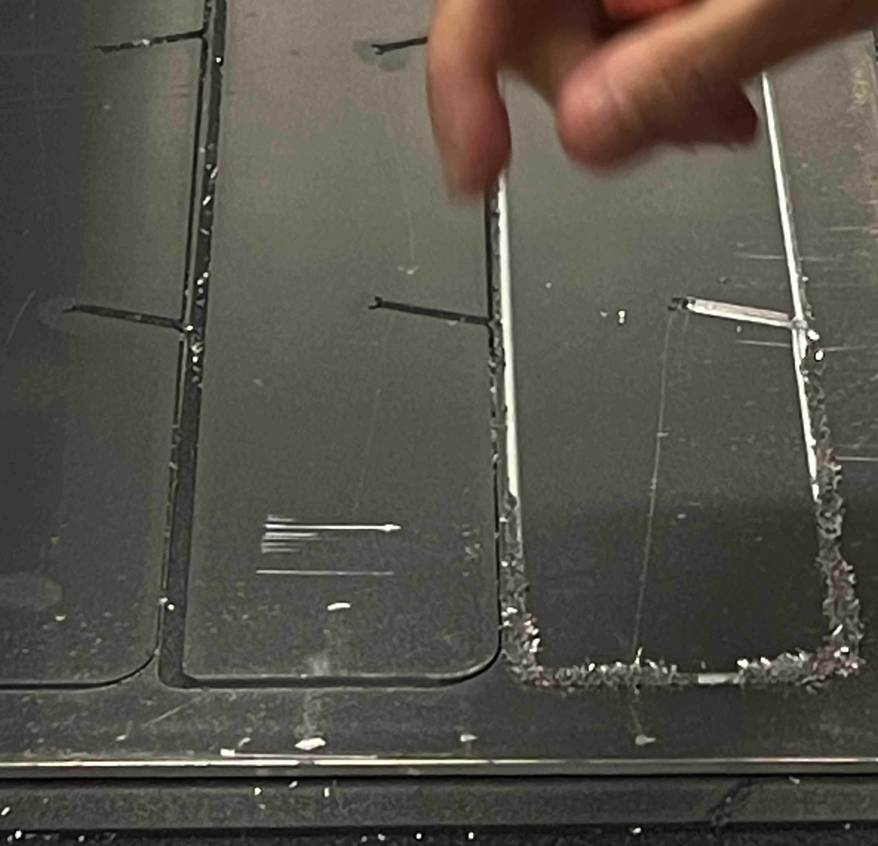
No digital fabrication is ever completely without error, here you can see where the aluminum began to weld into this crystalline fuzz. Not shown is the two times when the bit inexplicably broke. I think it's best practice to always account for potential error when buying material! Luckily I had enough stock to replace this slat.
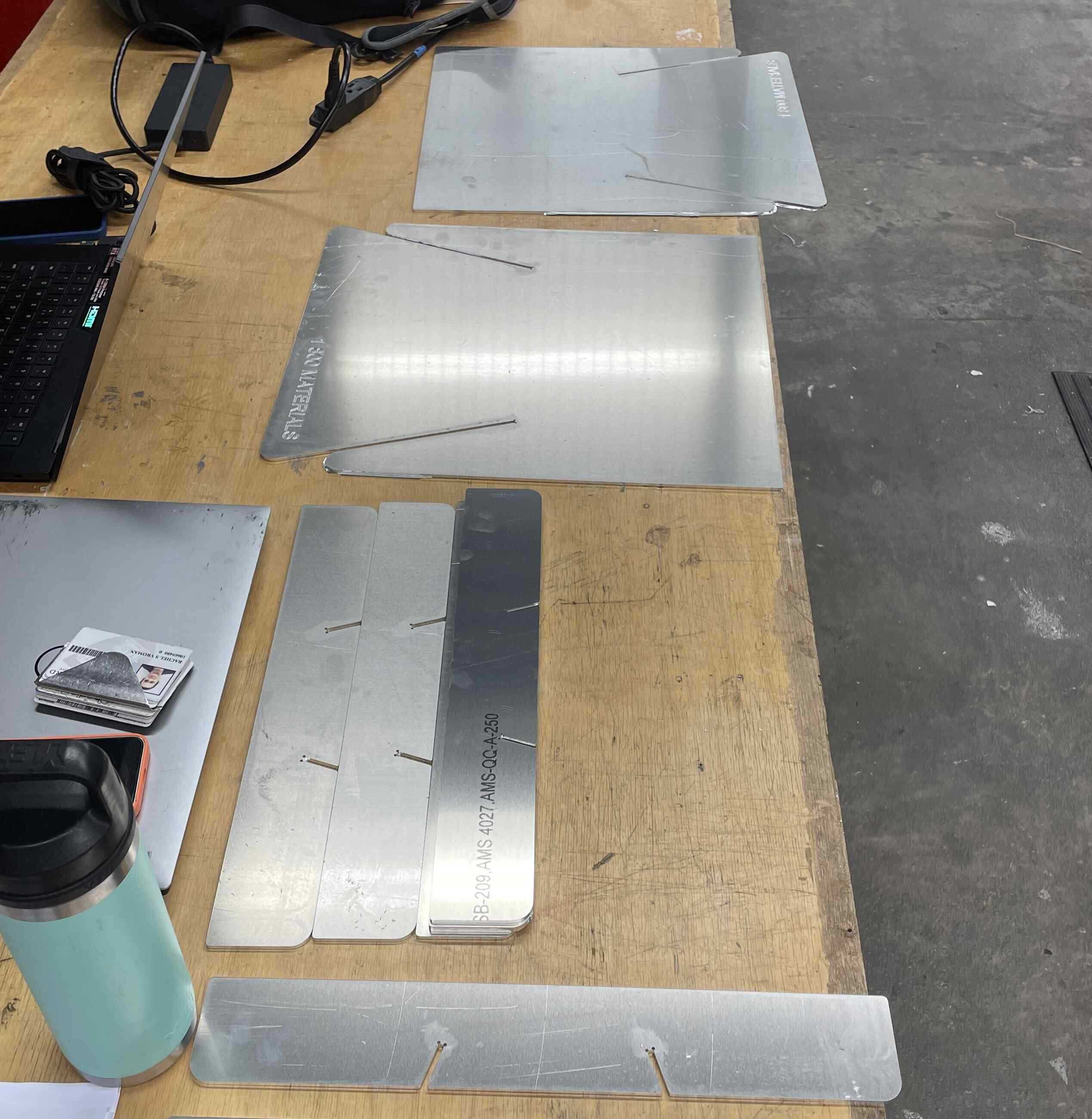
Once the pieces are cut out, you can quickly file down their edges to ensure they won't cut you.
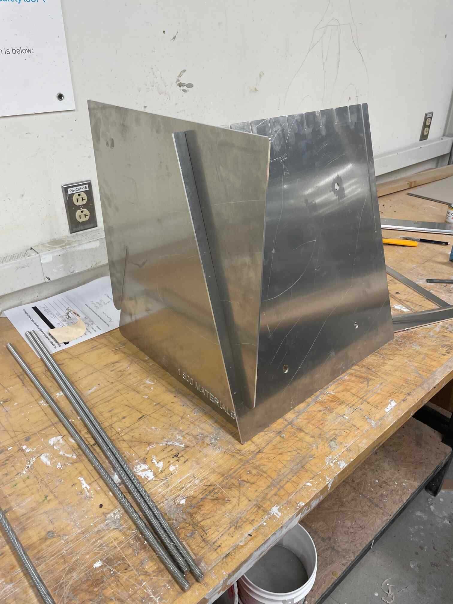
Things begin to slot together... The long joint ends up being a rather snug fit, while still coming together easy enough. I think this is because there is more opportunity for friction to be made along its length. Because the other joints are much smaller, they could afford to have a smaller tolerance.
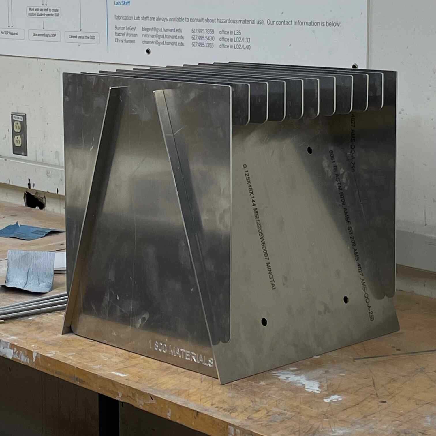
Everything slots together pretty easily before adding the tension hardware.
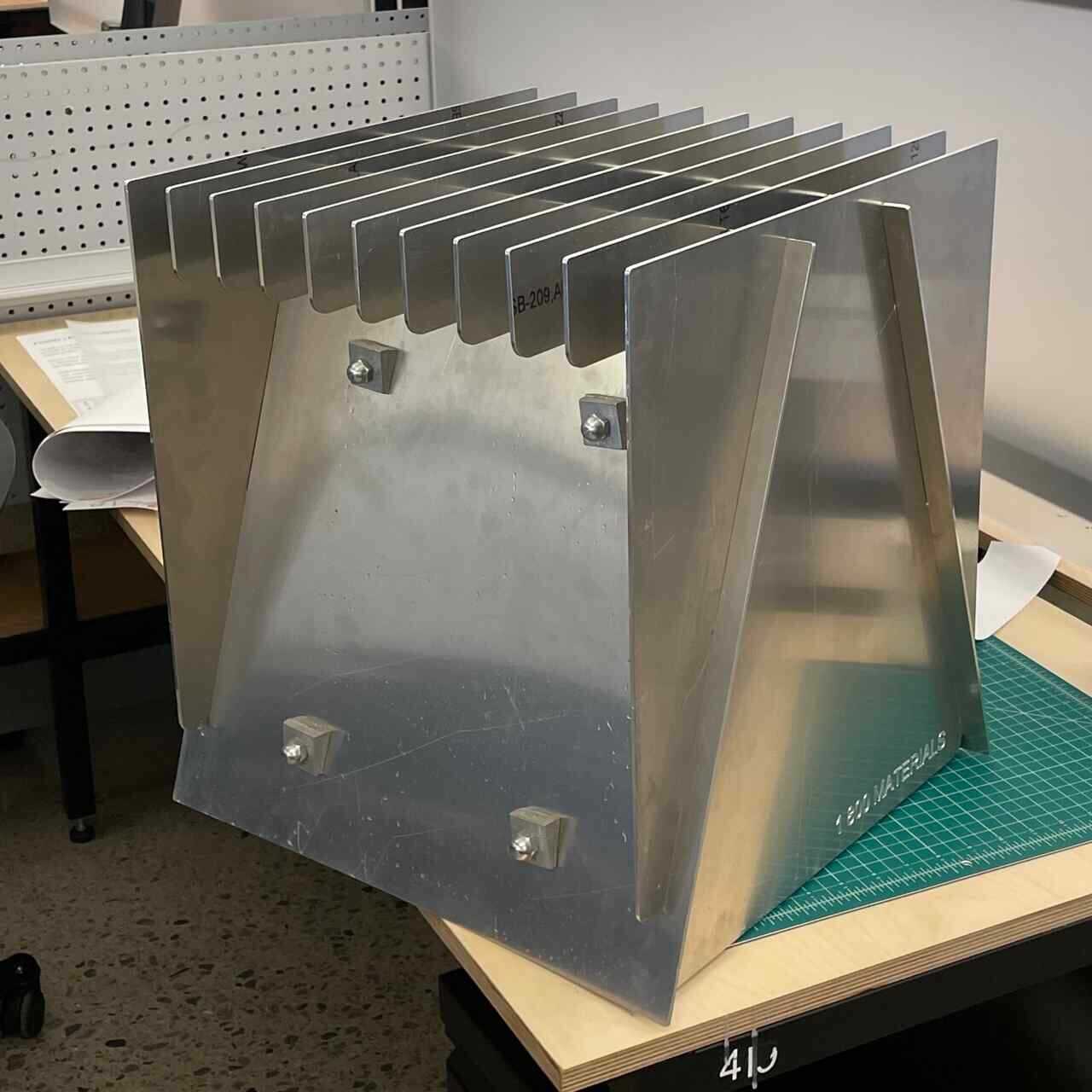
Hardware works! The tension is able to hold most of the top slats still, but a few of them have too large a tolerance, and not enough tension applied to keep them from jiggling around. Because of the geometry, there is no risk of them coming off or loose, but there is an annoying noise that I would like to fix for the next round [:
Part 2: Use the Lasercutter
For this part of the assignment, I wanted to design something parametrically in Fusion 360, that was modular and scalable. I decided to use cardboard, which is also 1/8" thick, because perhaps, if I liked it, I would maybe want to transfer this design to a more durable material. I wanted to test out a joint connection that locked, so I decided to try and model a snap-fit joint tile.
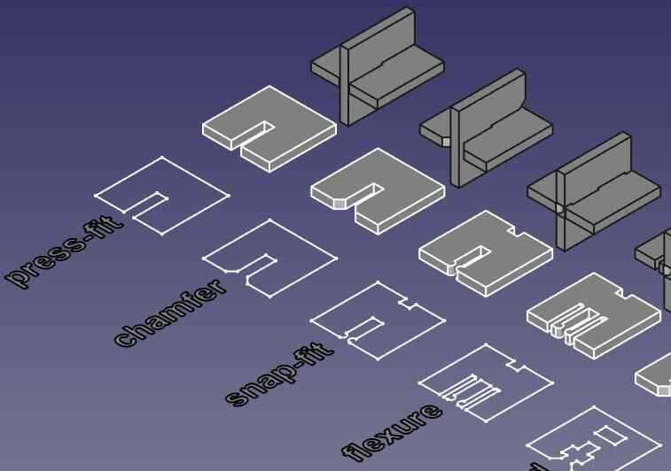
Working in sketch mode, I was able to draft a tile in which every proportion was parametrically associated to one another. This way, if I ever wanted to change the size of the tile, or use a material with a different thickness, I could easily alter its form in the parameter window.
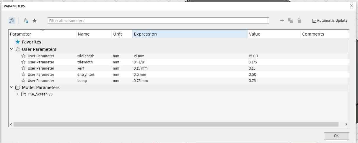
I parametricized the length from the joint to the corner, the width of the material, the radius of the snap, and the kerf.
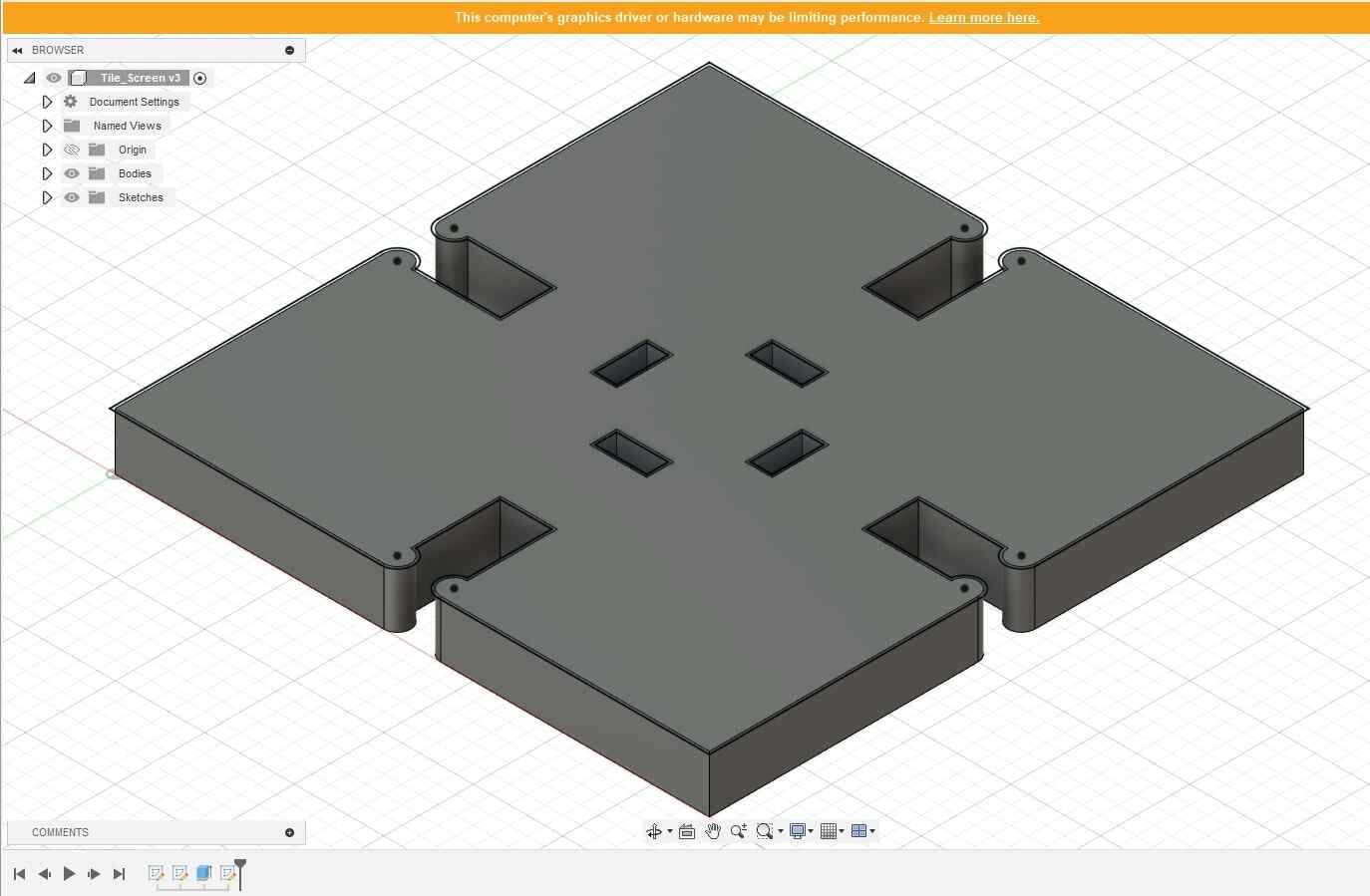
I extruded the sketch by the material thickness to get a sense of how the proportions felt. I also included an offset for each cut to compensate for the thickness of the laser.
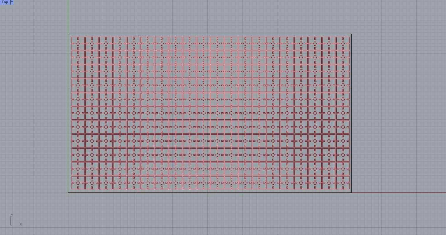
The lasercutters I was using print from rhino, so once I got my design down I moved over to rhino to lay my tiles out across the area of the laser bed. I then cut a piece of cardboard down to this size. The TA on duty told me I ought to lay the cardboard in the bed to where the corregation holes were facing out on the top and the bottom of the stock, in this case the long edge. This is so the air-pull is able to ventilate the interior of the cardboard while its being cut, to help prevent ignition. The TA also told me I should use the same settings that I would for bristol, but I found that I had to run the file 3 times just to cut through once. I decides to bump the power up from 15 to 28, which was able to give me a clean cut with just two passes, still without leaving any burn marks on the material.
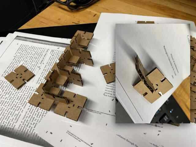
The tolerance was calibrated pretty well and the snapping mechanism worked but the cardboard had a hard time deforming past the bumps at the entrance of the joint. I think if I were to do this in metal or hard plastic, I would need to redesign it as a flexure joint. Nothing a little aggresion can't fix though [:
I realized because of the nature of the joint, it had to be assembled in strips, which were then linked together.
Bone Apple Teeth!