Actuate and automate your machine.
Document the group project and your individual contribution.
PHOTOBLEACH: The Bleach CNC to Rule Them All.
Two weeks ago in anticipation of machine week I suggest bleach CNC in the groupchat--not even a chirp. The day before we have to decide we do a preliminary vote, bleach CNC doesn't even make it into the top 5 (insane, I know). Yet by some twist of fate, after we tabled the discussion, slept on our conversations, and reconvened for a new round of presentations, bleach CNC finally got the love it deserved. By unanimous support, PHOTOBLEACH was pushed into the drivers seat.
There are a number of different subsystems within a PHOTOBLEACH-er. The idea is that the PHOTOBLEACH has a cartesian motion system, with a pump, and drip nozzle end effecter, and a camera. The camera can take your photo, use image processing to filter it into a useful pattern, and then this pattern can be scripted into a legible format that can drive the motion system.
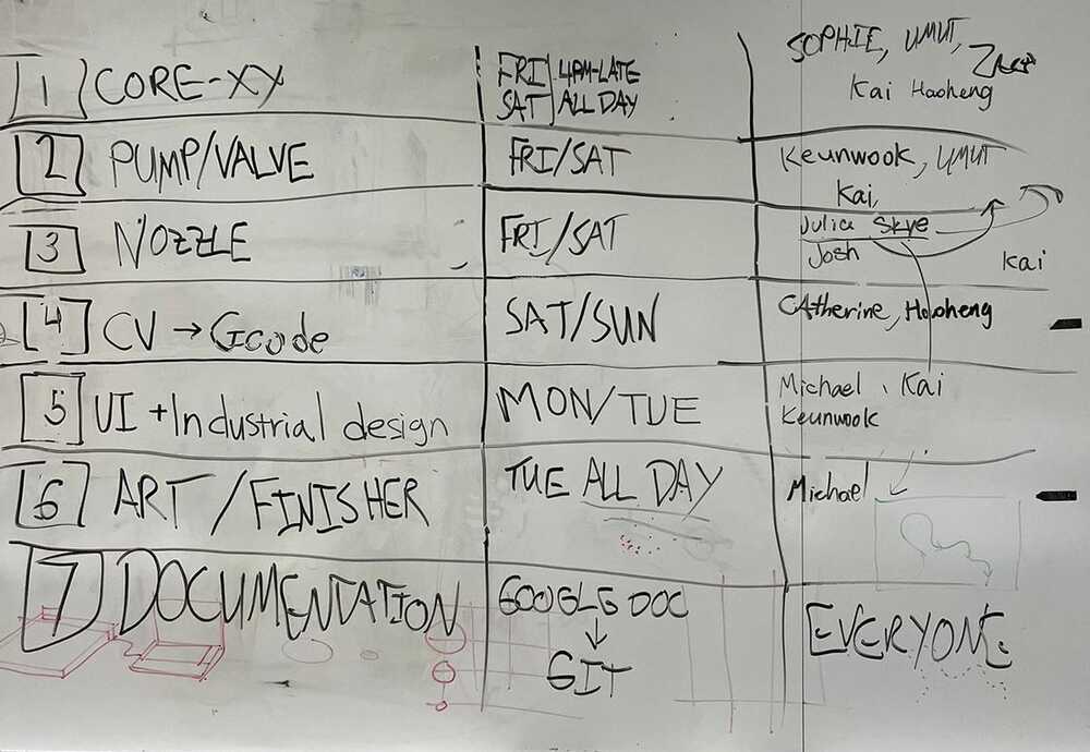
We split it up into HARDWARE and SOFTWARE. On the HARDWARE side of things, we had to construct the mechanism -- which we decided was going to be driven by a Core XY motion system --, we had to design a nozzle and connect a pump. On the SOFTWARE side of things, we need to drive the motors, we needed to have an interface to do this, we need to take a photo and have some algorithm to process this photo into a usable format.
This was the tentative list we set out on. I wanted to work on the Core XY subsystem since I've used coordinate operated machines a bunch but didn't have much of a clue as to how they operated under the hood. Core XY is just one way of driving a set of motors to produce XY coordination, but is useful for being fast and precise at the scale we are planning to operate on.
Step 1: Figuring out CORE XY
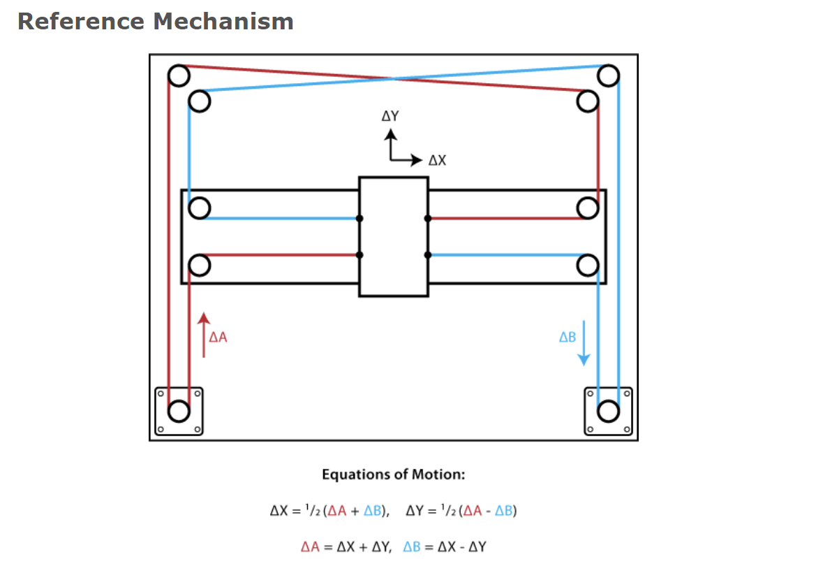
Once we decided we were going to move forward with Core XY for the motion system, we had to figure out how the mechanism worked. Turns out there's a number of different ways to do it, but we started by looking at HTMAA alum Ilan E. Moyer's website.
In this example the belts cross paths away from the stepper motors TA Jake recommended that we avoided this method because there are a number of failure-modes it could produce. TA Leo suggested we look to see how the 3d Printer Grid Bot Two manages Core XY.
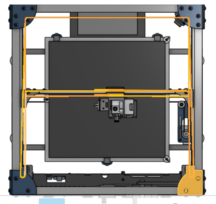
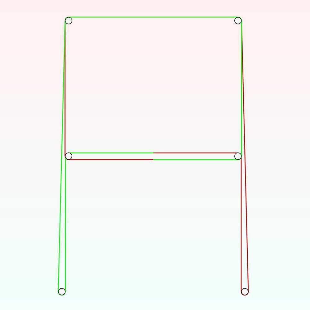
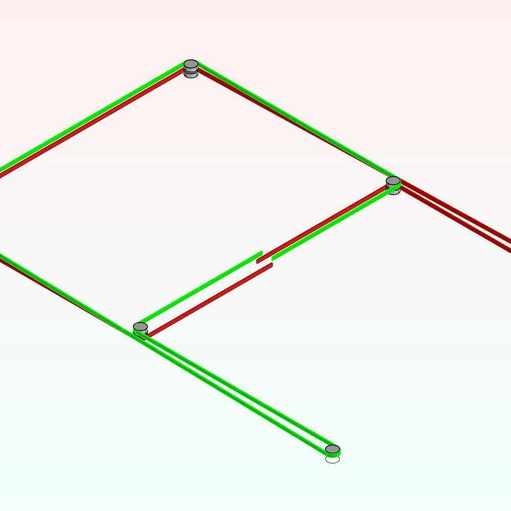
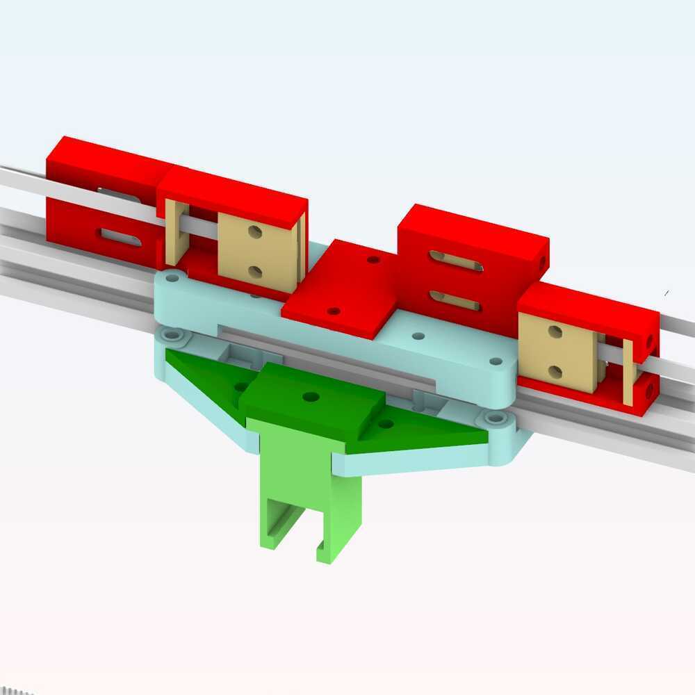
At no point do the belts cross in this schematic. Figuring out the trick behind these belt designs can be tricky, so we thought it was best to try and model the belts to see how they were able to move past one another without causing any friction.
After I modelled it it was a lot easier to understand the finesse behind this design. The important details here are that the top four idlers are all orthogonal to one another, and they are all stacked idlers, having two per spindle. The bottom two are gears, and they are attached to the stepper motors. The one controlling the green belt is situated in a z-plane above the one controlling the red belt. And lastly, each of these stepper motors is offset the orthogonal axes of the top four-set by exactly 1 diameter + 1 belt thickness. This keeps the interior stepper leg of both the green and red belts perfectly straight with the interior idler legs above it, while creating a diagonal that prevents a belt collision near the middle idlers.
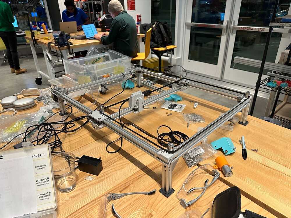
Step 2: Acquire the Parts
A lot of components go into making this mechanism, some of which are off-the-shelf, others of which we'll end up having to make somehow. Lucky for us, this machine does a good job at making use of many of the parts included in this week's kit. Let's take a survey of what we got and what we'll end up needing to make.
INGREDIENTS:
[included in kit] 2 NEMA17 stepper motors
[included in kit] 2020 V-groove aluminum extrusions 1000mm (framing rails)
[included in kit] Extrusion Corner Brackets
[included in kit] Extrusion Post-Install T-Nuts
[included in kit] 5M GT2 Timing Belt 6mm
[included in kit] 625 Ball Bearings (20 count)
[included in kit] Washers M5
[included in kit] 5M GT2 Timing Belt 6mm
[included in kit] SHCS M5 Bolts x Various Lengths
[included in kit] FHCS M5 Bolts x Various Lengths
[included in kit] Standard 3D Printer Roller Wheels
[need to fabricate] Sliding Brackets with Idler socket
[need to fabricate] Corner Brackets with Idler socket
[need to fabricate] Corner Brackets with Motor Attachments
[need to fabricate] Z-Stage with Belt Clasps
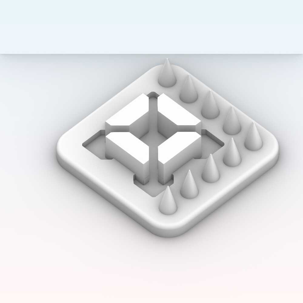
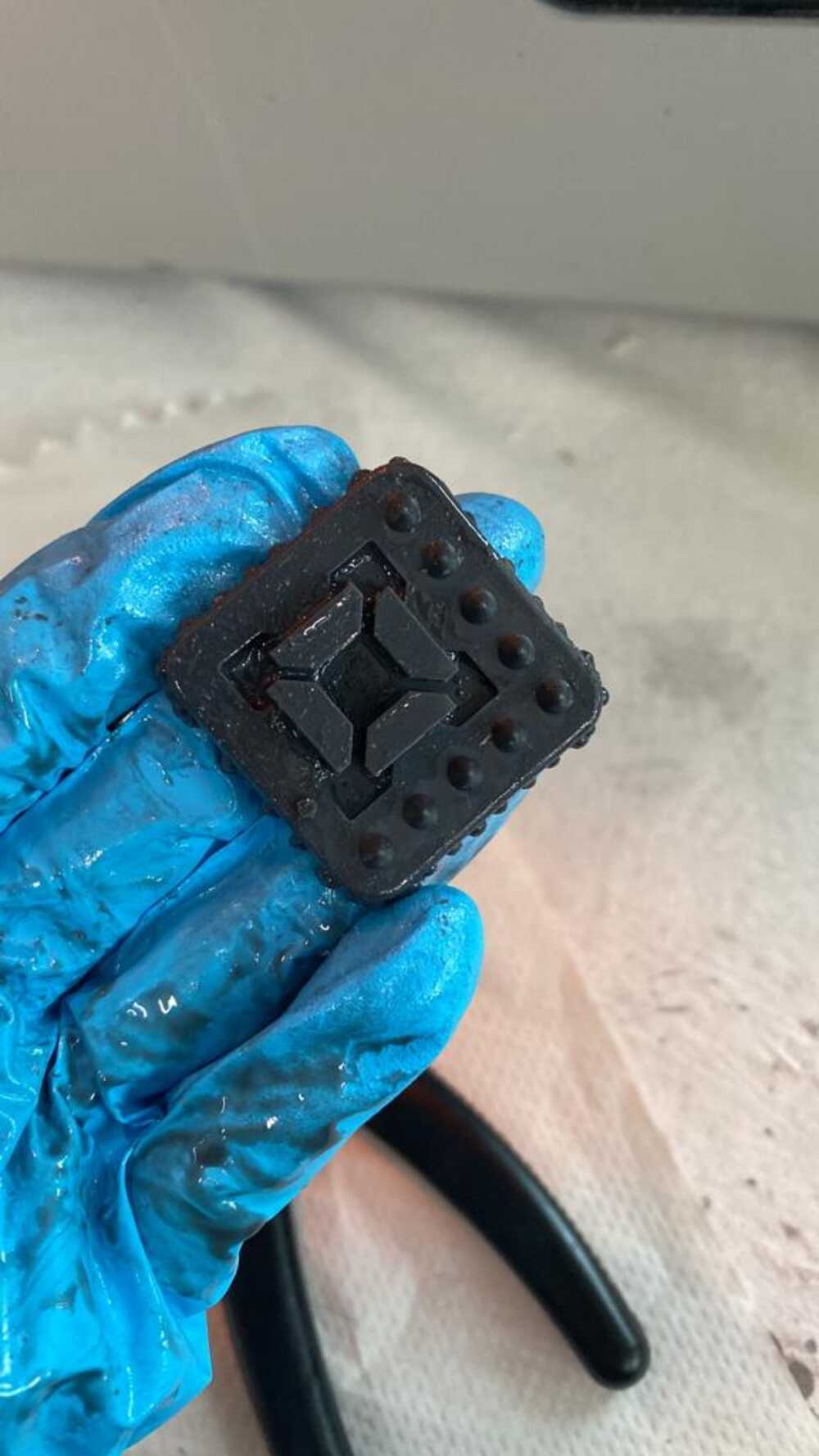
[optional but recommended] Little Footies with Spikes c;
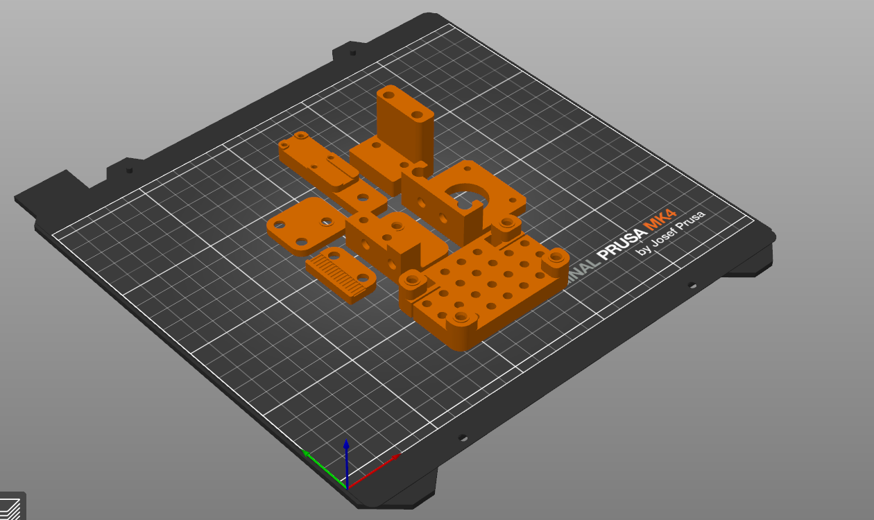
There were some example pieces that were provided one of which (the one closest in this photo) was used as a base for the sliding joints.
We started by testing the fit on this first. It seemed okay, but it wouldn't be clear until we run into more dependencies that this piece would prove inadequate.
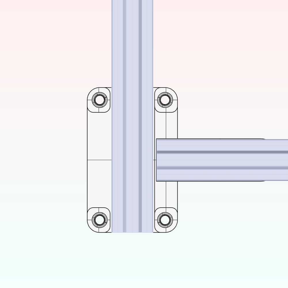
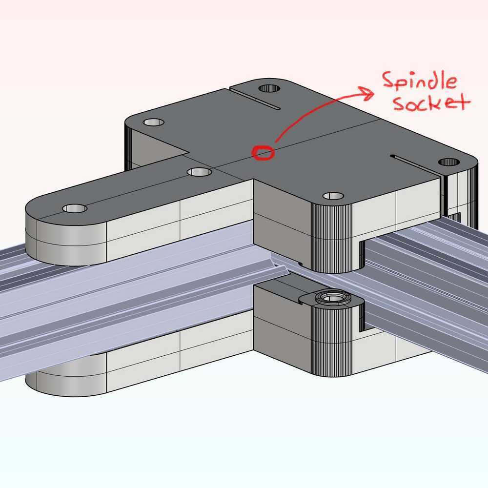
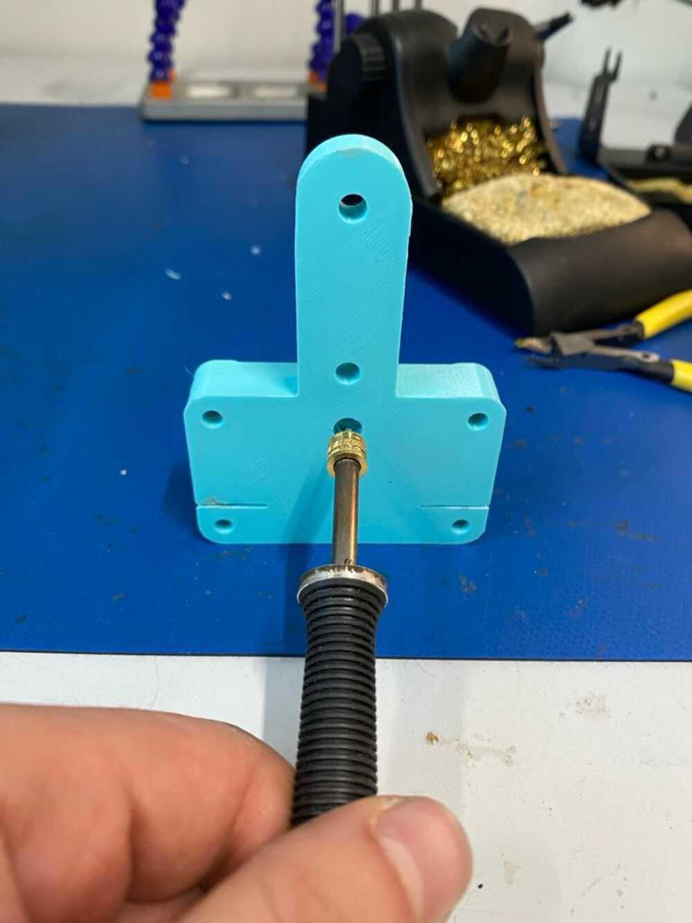
I modelled these adjustments onto the starting geometry to test out this sandwich joint for increased rigidity as well as providing a moment connection for the gantry arm. Umut had suggested we use a type of threaded socket that you can place into the PLA using a soldering iron, which could give the idler spindle plenty of rigidity.
They look like this.
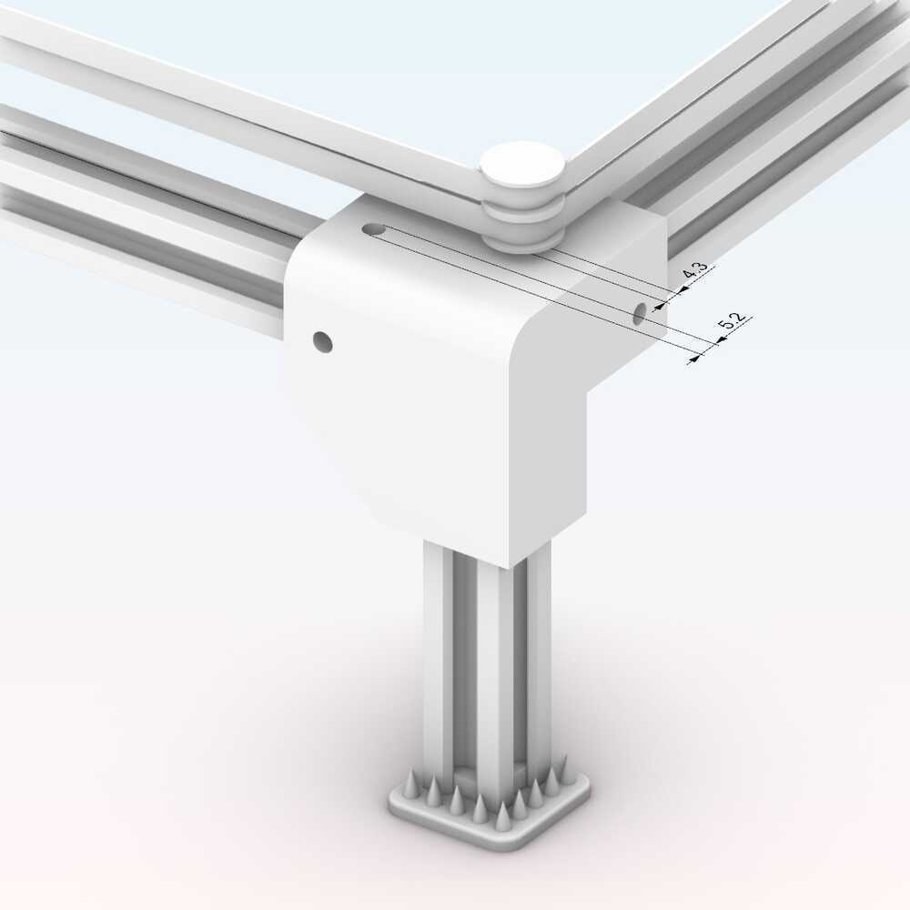
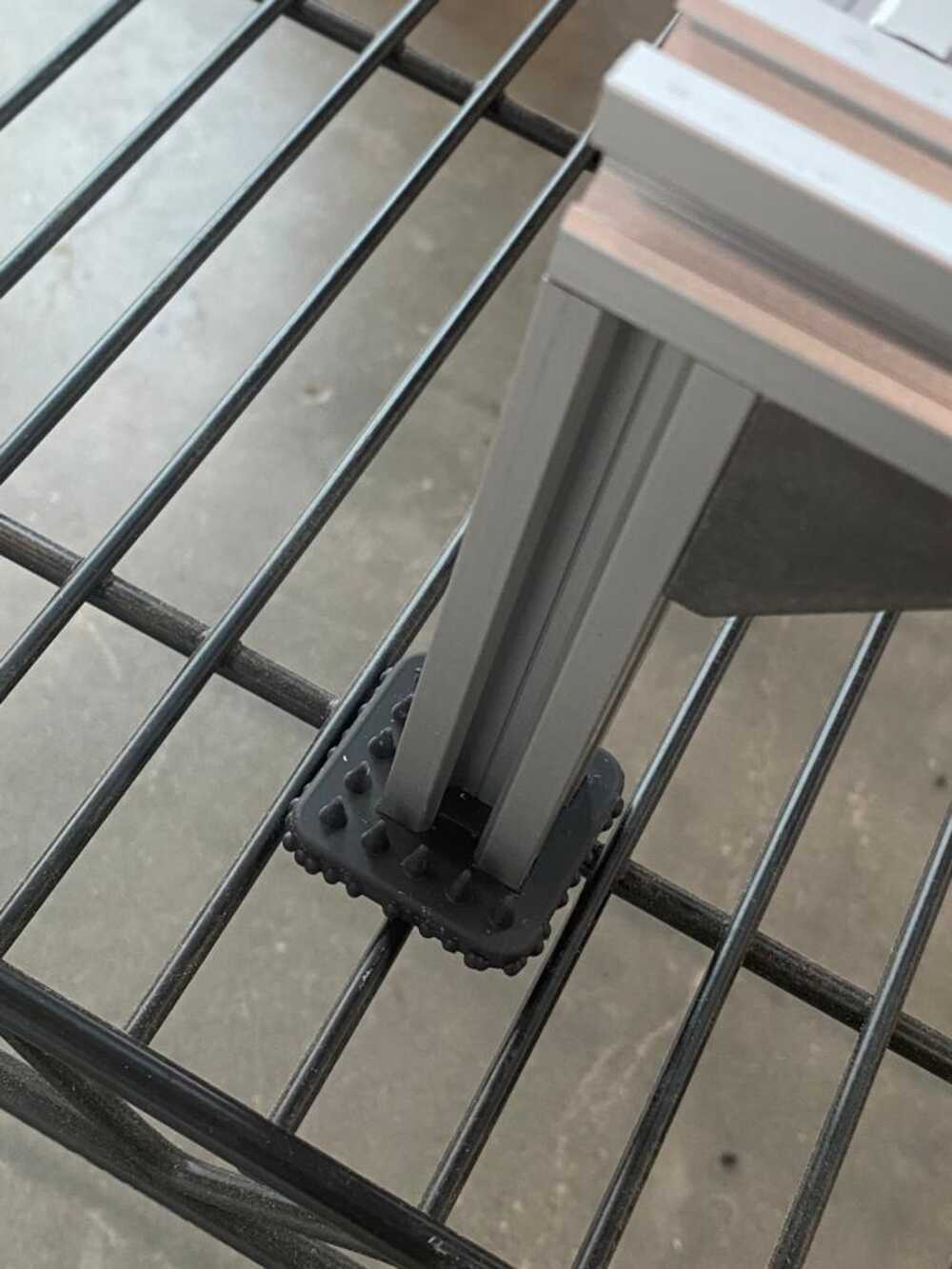
While Umut was going ahead and cutting the aluminum extrusions down to the proper size, I continued to model the first test prints for the machine. I set up a corner detail, and make spiky footies for maximum stability. Crucial element.
The pieces come together and it slides! Exciting progress. The stacked idlers seemed to sit well within the heated socket.
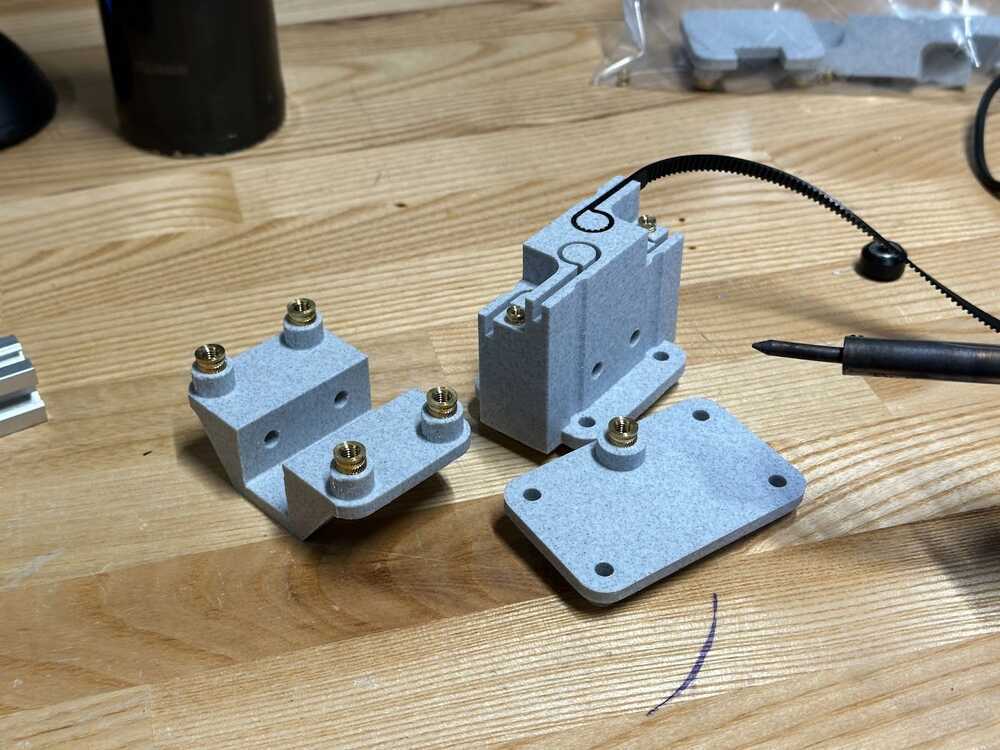
We needed an assembly the could hold the collet, slide horizontally on the gantry, grab the belts and post-tension them. Our first thought was to have all of these functionalities combined in this area of the machine, but this would prove less than ideal because it would reduce the total print area available by about half. Its form factor was too long. Leo also raised a concern that the sandwich pieces were slightly not as tight as they should be. It was time to for revisions. Quincy was around to take on the second round, and this is what we ended up with:
These parts had better tolerances than the piece from the kit I altered, and the belt capture detail on this saved a ton of space on the print bed. You don't need what you don't need.
Step 3: Put them Together
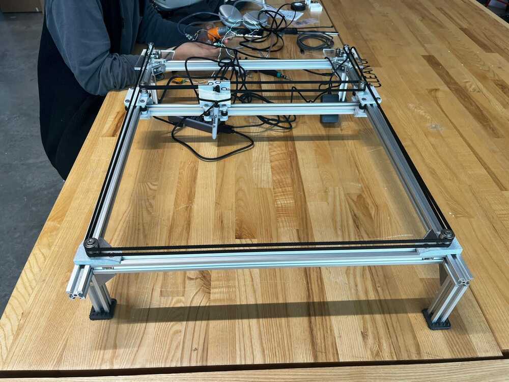
We reassembled it, and ran into the post-tensioning issue again. The belts were sitting a bit too loose.
After Leo, Sophie, and I muddled about it for awhile, it dawned on me that we could just afford to lose an inch and a half of printing space and use the entire bottom bar as a post-tensioning device. We reset the location of the corners, reattached the belts to Quincy's print, and I pulled that back bar back while Leo tighted down all the nuts. It seemed to work pretty well.
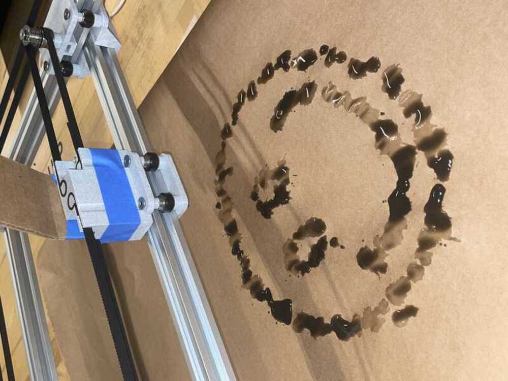
It's time for baby's first steps.
Sophie jumped into the software and started to drive the motors.
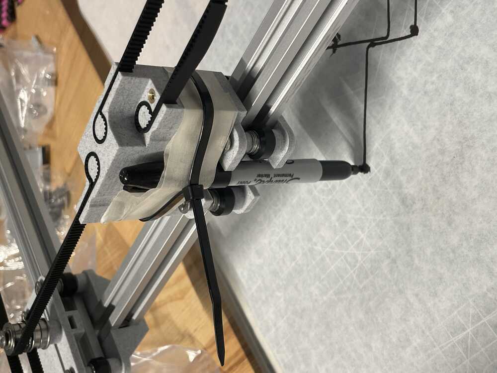
Once we got the mechanism working, I threw a ziptie on a sharpie and pivotted to attend to my other finals, coming back mainly to work on small details and compile our documentation onto the shared webpage. Learned a lot about the hardware and assemblies involved in making motion systems. Doing this makes me really want to do it again on my own time so that I can pair this knowledge with the software we used to drive the stepper motors.