Individual Assignment Prompt:
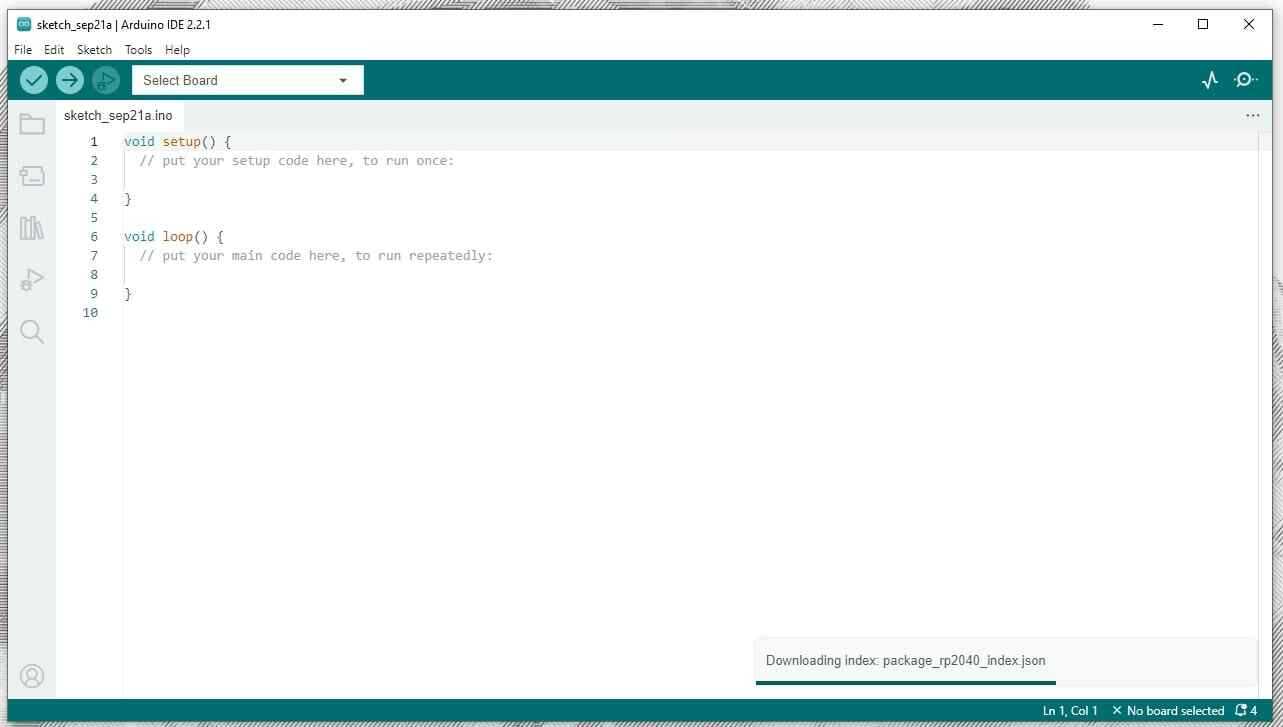
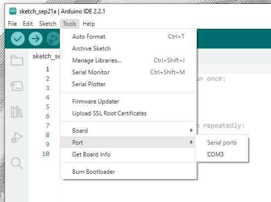
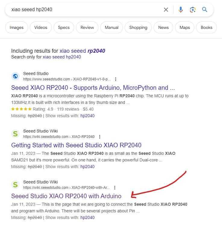
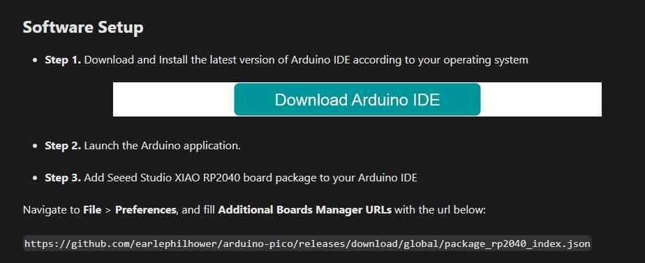
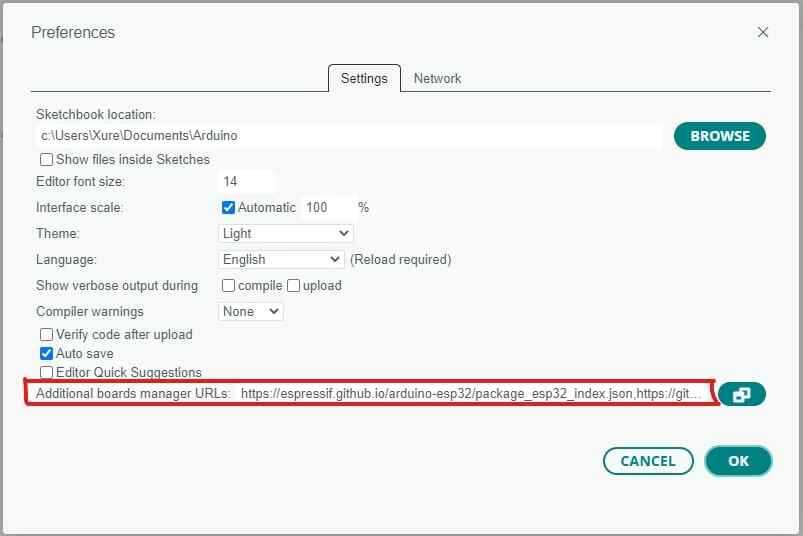
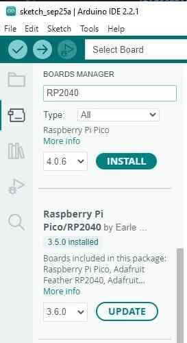
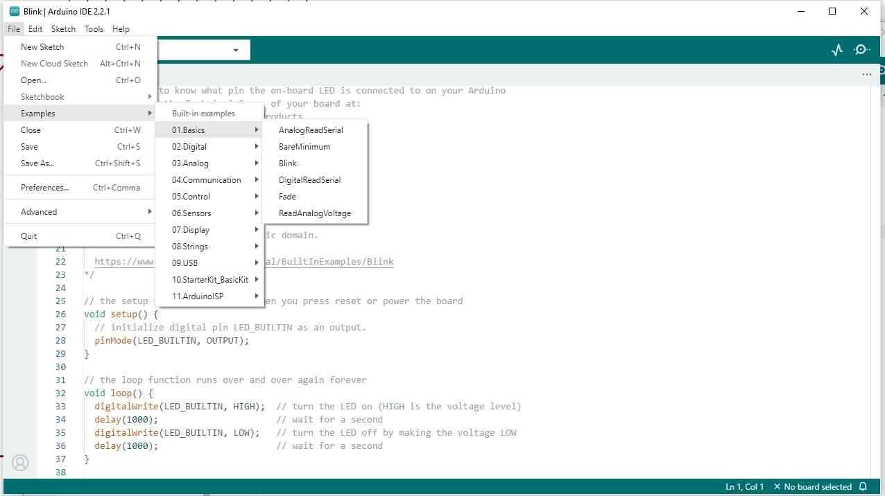
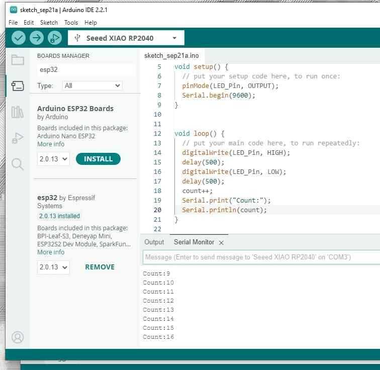
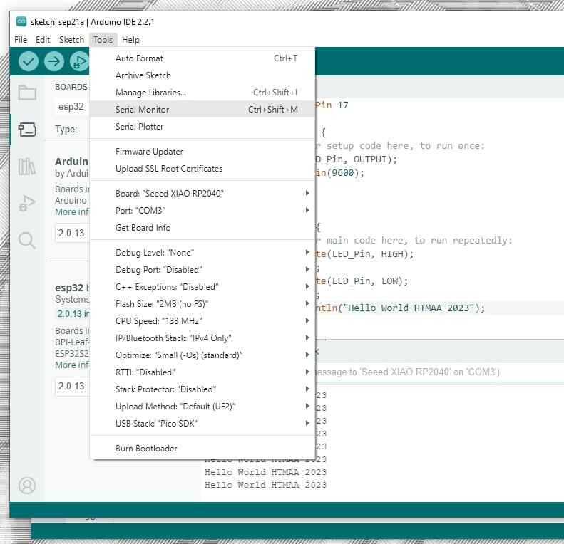
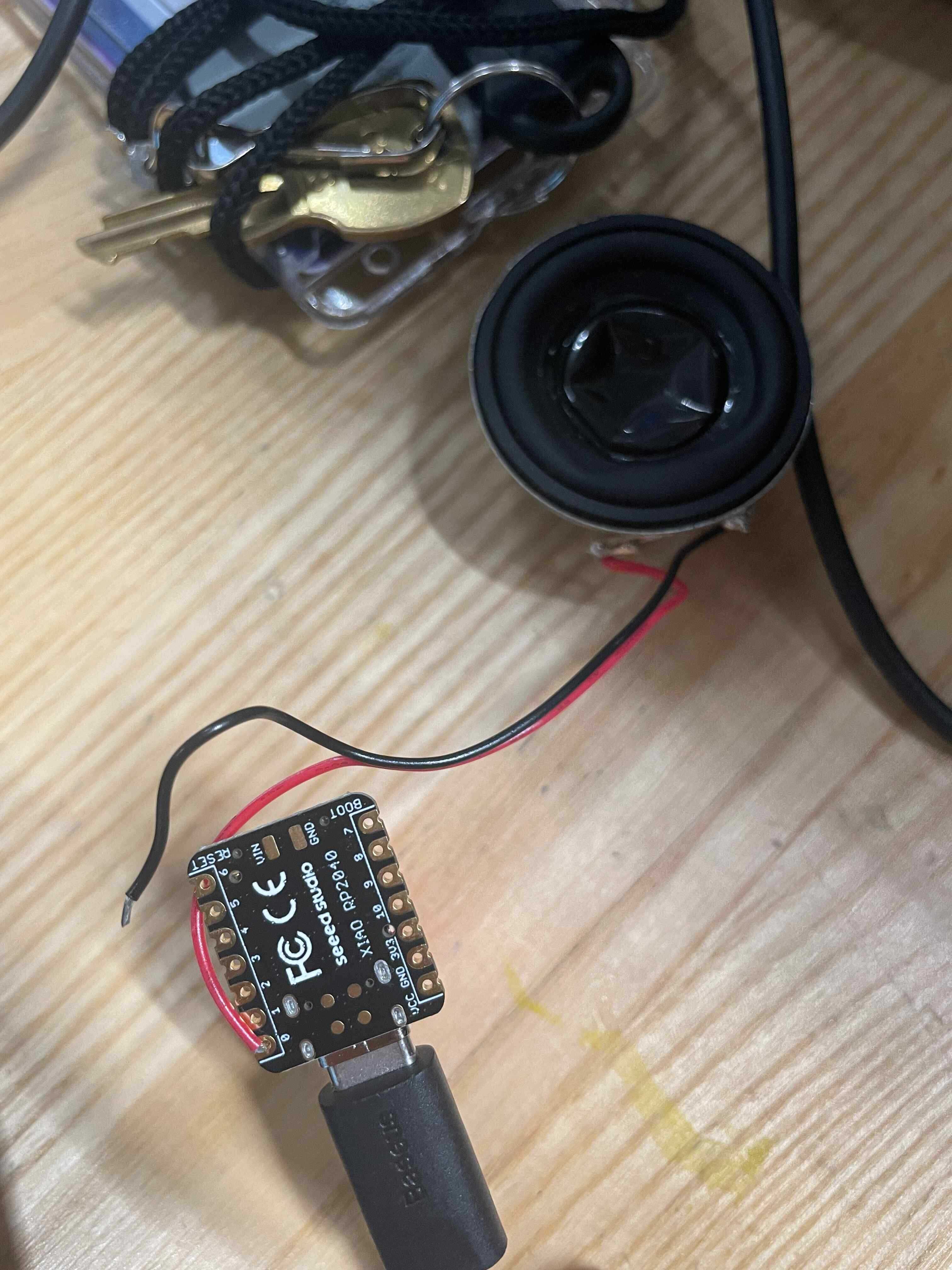
- Write program for a microcontroller development board Having absolutely no experience with embedded programming prior to this class, I decided to start with the Arduino IDE. The Arduino IDE has a number of pre-loaded libraries and scripts to help one start learning how to engage with a microcontroller. In how I've come to understand it, the Arduino IDE has bootloader scripts built into it, so once you select which microcontroller you are using and choose which language you intend to code with, it automatically configures the microcontroller to be able to process this code. This is what the IDE looks like when you open it. I am using the Xiao Seeed HP2040 Microcontroller, which uses a USBC connection. So the first thing I had to do was get one of these cords. Once you have that you can just plug it into your computer. If you -> Tools -> Port you will be able to see if you have a port connection. For Windows, this will be COM + some random number. This is my RP2040. Select this port. Next step, you need to set up the Arduino IDE to be able to talk to your board. In order to do this, you need to look up your board and find its manufacturer's website. Follow the steps. Copy the link at the bottom of this screenshot... And paste it here! Files -> Preferences. If you are working with multiple boards, you can click the button to the right of the URL and add additional URLs. I added a Boards Manager for both the Xiao RP2040 and Xiao ESP32 (which has wireless connectivity capabilities) Once a board's URL is added to your preferences, you should be able to search for it in the "Boards Manager" UI on the lefthand side of the page. You're going to want to download this one by "Earle". If you're not sure which one to download, check back to the manufacturers page to double-check which boards manager your URL is referencing. These are the fancy pre-loaded scripts I had mentioned Arduino IDE having earlier. This is a good place to start if you're looking for a framework, from which you can adjust to fit your more specific needs later. This script got my LED to blink, and by controlling the delay, you can control the speed of the blink. Additionally, HIGH, is simply what this microcontroller sees as sending 3.3 volts, LOW is 0 volts. Once you have the code onto the IDE screen all you need to do is hit "Upload", which will first verify if there are any errors, and then embed the program onto the microcontroller. It blinks! We have communicated with the microcontroller! Now... to get it to communicate back to us... This will require adding some basic C++ commands. You have to add a Serial.begin command to your setup, and then add it to your loop. In our case, we will be using Serial.print, which will print us a value everytime the microcontroller blinks. Don't think of this as a code that knows how to count. Think about this as a code that knows when the microcontroller blinks, a message is being sent to the microcontroller to blink, and the microcontroller is now taught how to speak back to the computer. In order to see this, you will have to go to -> Tools -> Serial Monitor, which will open a UI window to display whatever it is that the microcontroller is saying to you. Okay. So the LED inside the chip operates in essentially the same way as any of the other pins on the microcontroller, in other words, those conductive pads lining either side. Each of these pads have "pin" numbers, which can be summoned by the program to release a voltage. So what now if we wanted to use one of these pads, and connect something to our microcontroller? I want to attach a speaker to the microcontroller using pad #0, so I attach the red (power) wire to this terminal. The black wire will need to be used to ground, completing the circuit. Do not attach the black wire to another power source or it will short circuit and damage the microcontroller. To test this I go back to the example pre-loaded scripts, and pick one that has a sound component. After hitting upload, and grounding the speaker to a grounding pad on the back surface, it works! Happy Birthday! :D
to interact (with local input &/or output) and communicate (remotely)
- Browse through the data sheet for your microcontroller
- Extra credit: use different languages &/or development environments
- Extra credit: connect external components to the board
Part 1: Write Program for a Microcontroller Dev. Board