Individual Assignment Prompt:
- Use an EDA tool to design a development board to interact
and communicate with an embedded microcontroller
- extra credit: try another design workflow
- extra credit: design a case for it
- extra credit: simulate its operation
Circuit Design
This is a week! This is totally new for me, which is exciting, though unfortunately I wasn't able to start getting into it until Monday when I got back to Cambridge from Ghana. I started by watching the lectures, which was helpful for getting the software setup and getting a general lay of the land, but I quickly come to realize that I don't know how best to teach myself yet when it comes to electronics. I don't really know where to start, but assume it has something to do with a block diagram and a datasheet.
Office hours won't be available until the night before everything is due, so I thought it's best to at the very least have a clear enough idea of what kind of circuit I wanted to make so that I can make something that will actually serve to be useful for me moving forward with my final project.
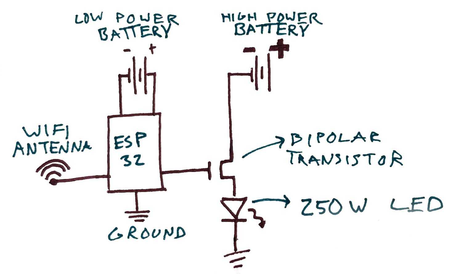
I knew that I wanted to wirelessly communicate with a transistor which could actuate a circuit of a much higher power rating than the microcontroller could handle. Eventually, I want to be able to remotely control a grid of spotlights, so this seemed like a good first step. I chose the XIAO ESP32-C3 as the microcontroller of choice because it has built in wifi communication capabilities. Skye Gao recommended that I use the XIAO RP2040 with a radio antenna attachment because the school wifi servers have security barrier that make it hard to communicate over wifi. I was tempted to do this off her advice, but TA Quentin suggested that with local hotspots this shouldn't be an issue, and that one added benefit of experimenting with WIFI is that you don't have to be in the room to communicate with the XIAO, you don't even need to be on the same WIFI network, as the communication will be travelling through the internet. This has a lot of useful functionality if not for this specific project for perhaps other things that I'd want to do in the future.
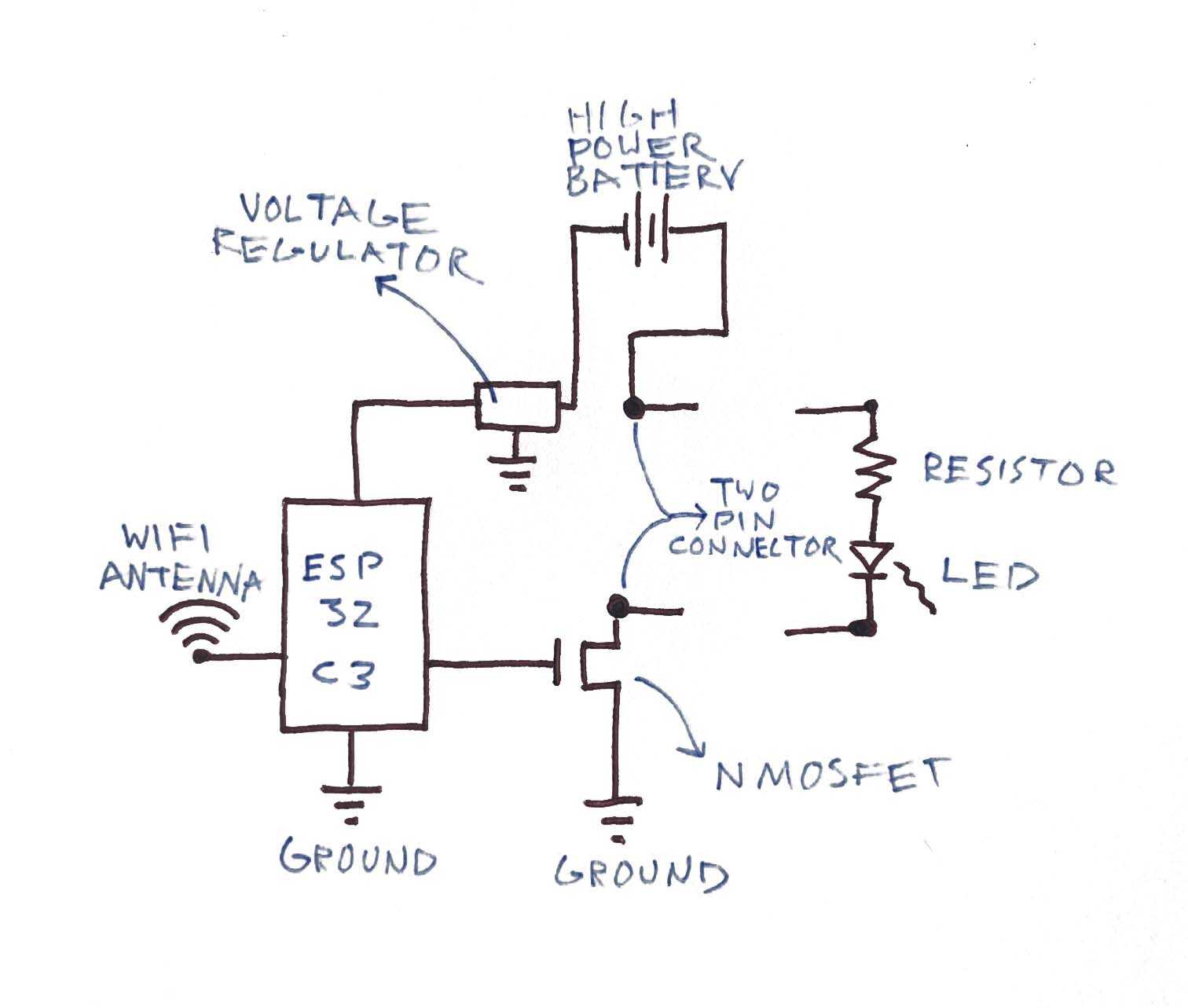
After showing the previous diagram to Quentin, he thought it was redundant to have two power supplies, one for a high power function and one to power the low-power microcontroller, and suggested that I use a DC/DC Converter instead to drop the voltage down for safe consumption by the XIAO. He also suggested that the design could be a little less explicit about what high-power function needs to be activated, and adding a pin connection could keep this functionality adaptable. So in this case, the LED and its resistor would belong to its own module.
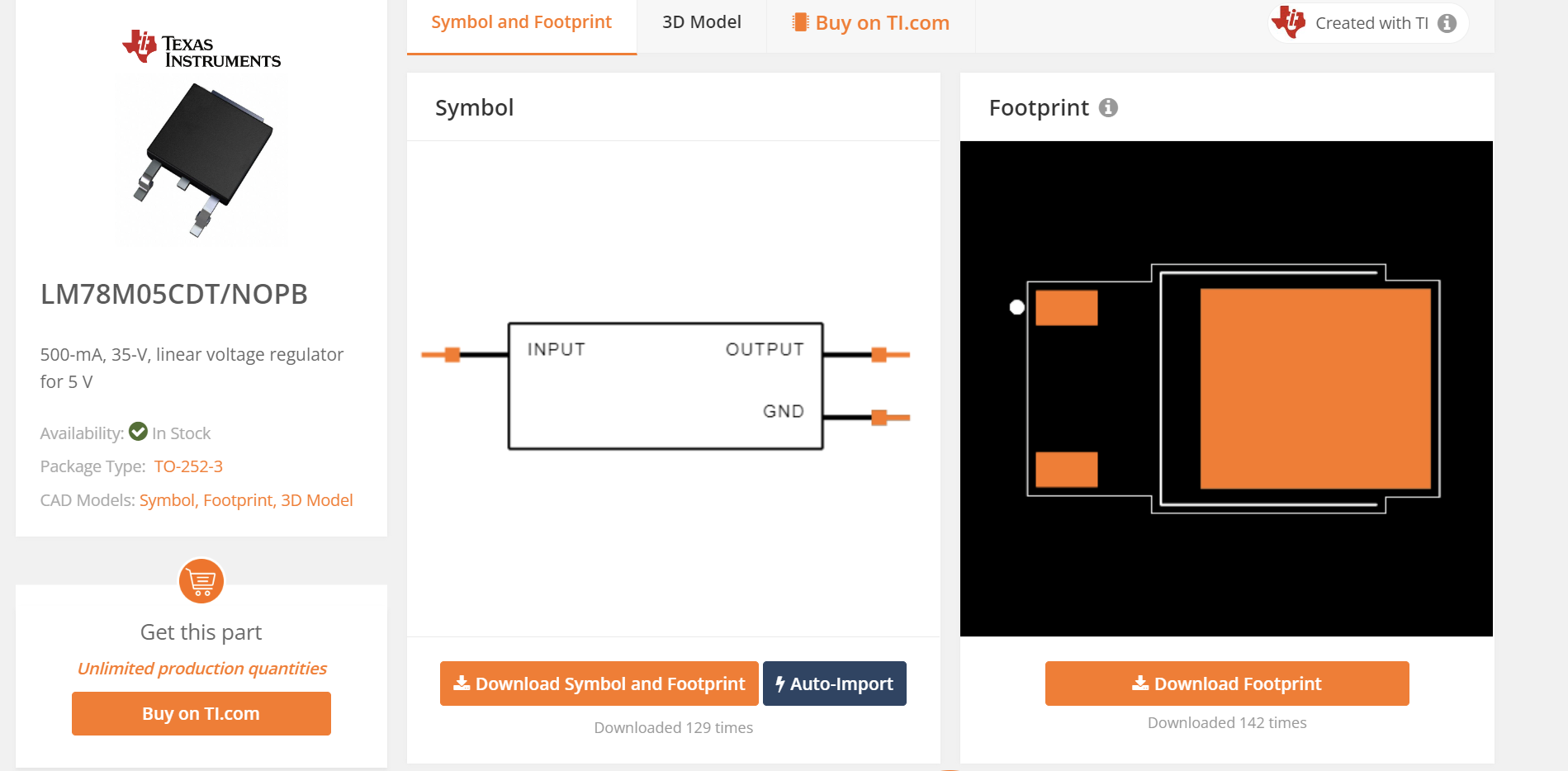
Knowing that I was now going to need a voltage regulator, I searched SnapEDA for DC/DC Converters. You can download a part's symbol and footprint directly from this website, and then add it to KiCad just as you would the fablab libraries (great walkthrough of this shown by Quentin in this years recitation video, posted on the HTMAA website). In order to see if this would allow me to jump from a 9V battery to a 5V power charge for the XIAO, I checked the datasheet.
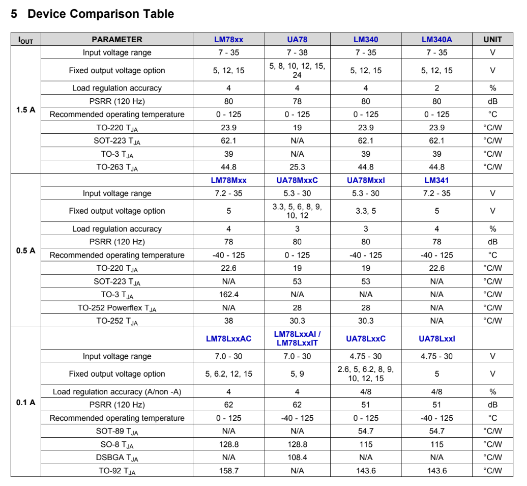
Here you can see that it has an input voltage range of about 7-35 depending on amperage, and has a 5V fixed voltage output. Should do the trick. As mentioned earlier, for my final I am thinking of having a grid of spotlights. This means that if I am to have them all hooked up to a powersource more powerful than my XIAO can handle, each one of them is going to need a transistor. But how can I have 16 transistors, when there aren't nearly enough pins on my XIAO EPS32?
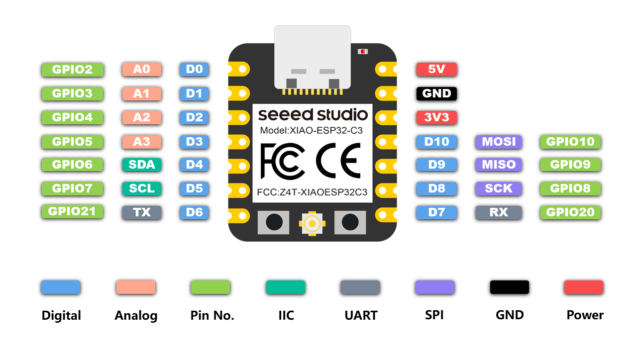
At best, I have ten pins and a 3V3 and 5V that could maybe be rigged to send a signal. This still isn't enough for 16 transistors. I was wondering if I would need another XIAO, but that seemed redundant. I asked Quentin if there was a way for me to add additional pins to a single microcontroller, each with their own unique ID, and he suggested that I try to find a multiplexer. Back to SnapEDA!
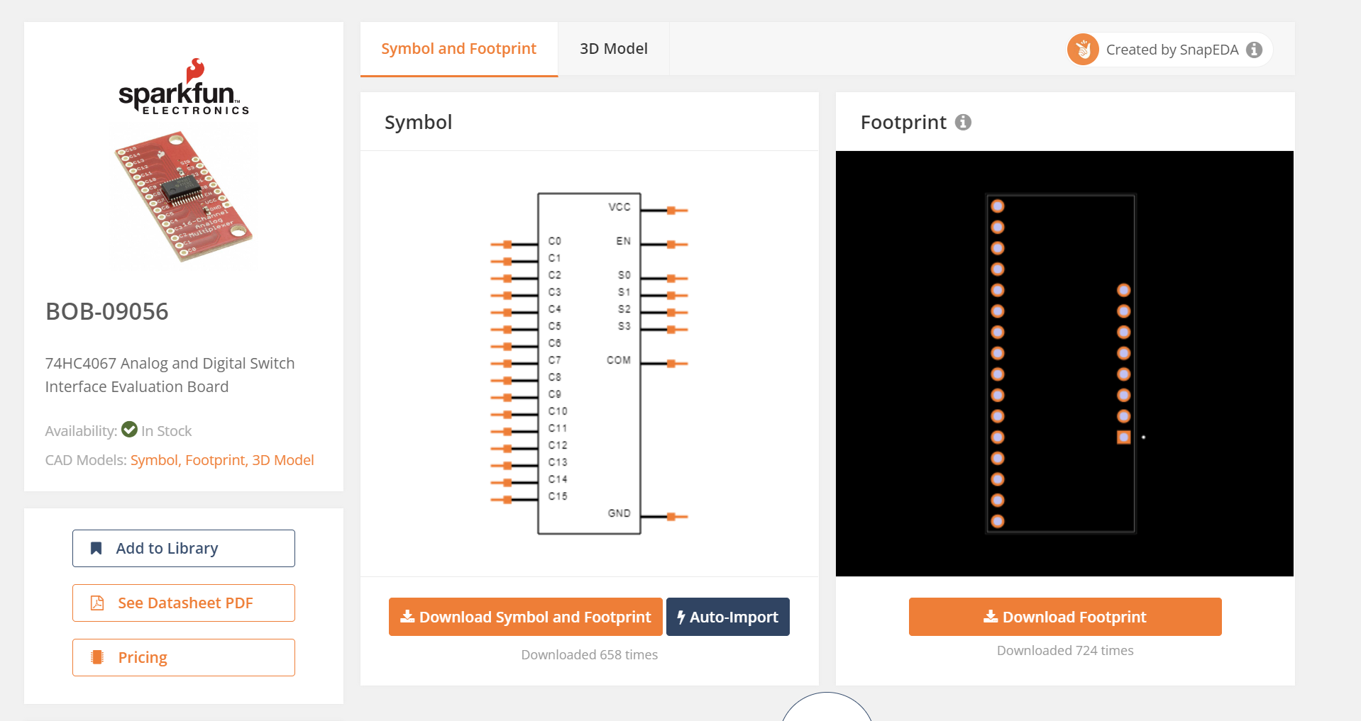
I found this multiplexer by SparkFun that seemed like it would do the trick. If you open the datasheet you can see how it is able to use 4 inputs to code for 16 outputs. It's what they call a "truth table".
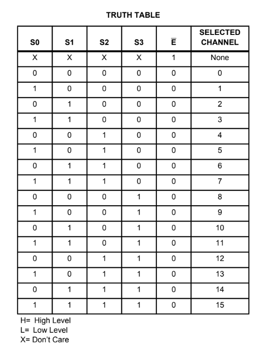
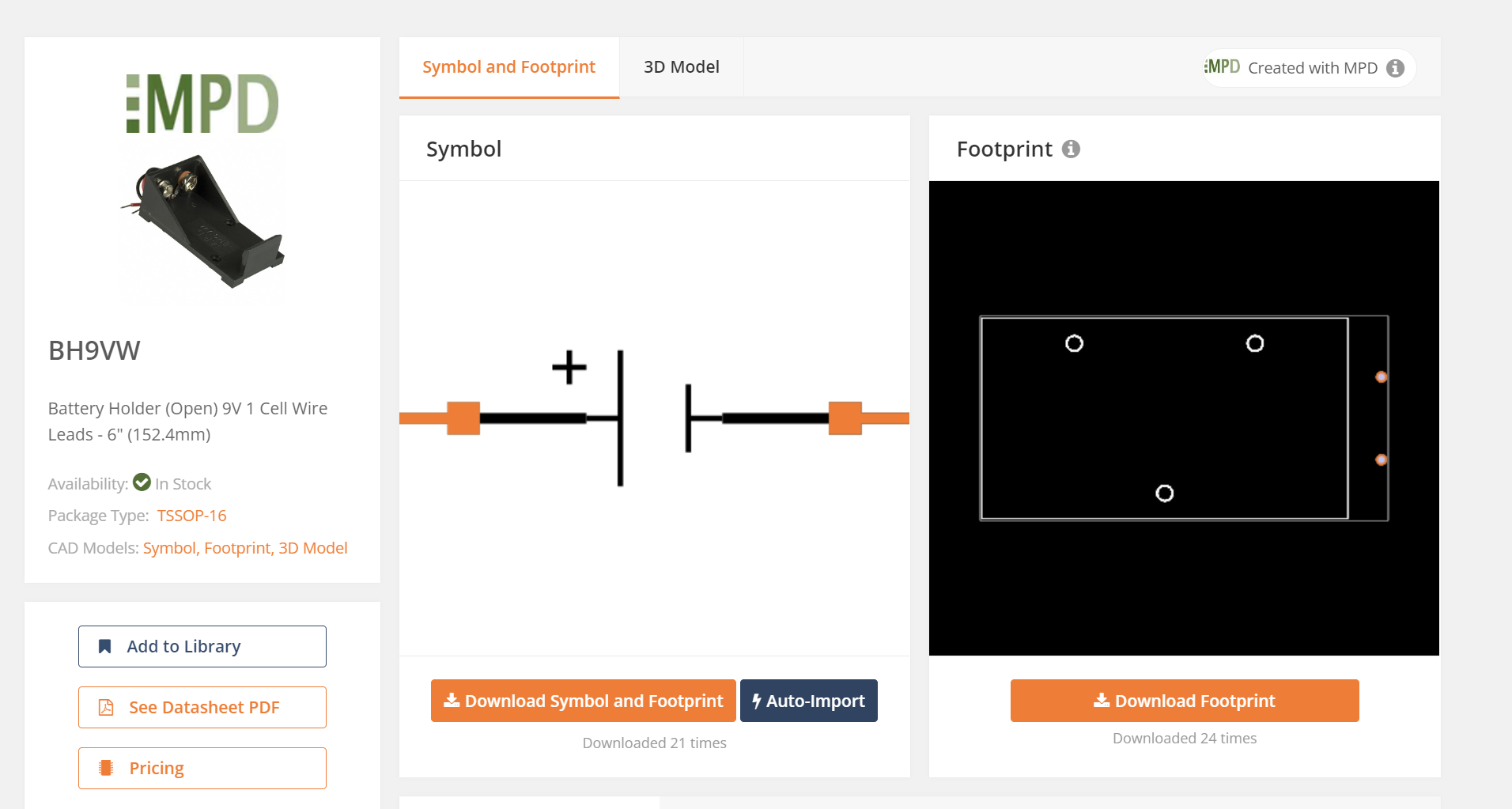
It's pretty simple math. I downloaded its symbol and footprint. I needed one last piece, the high power supply. For this experiment circuit I'm going to try using a 9V battery before trying anything larger, so I grabbed this 9V battery holder off SnapEDA. Pretty straightfoward (I hope lol).
Time to jump in KiCad's Schematic Editor.
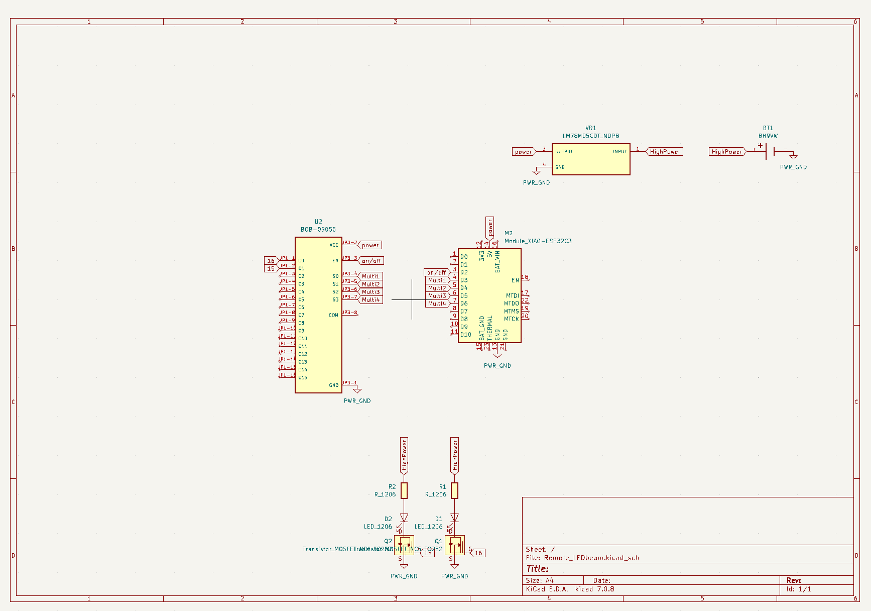
So, since XIAO has built in wifi capabilities all I need to do is add an antenna to the microcontroller itself and don't need to account for this in my circuit. I have a multiplexer attached to 6 pins on my XIAO, it needs a 5V powersupply, a pin to signal on/off, and four pins to signal the 16 available outputs. For the sake of getting started I am just going to use two of the available outputs. Each of these outputs is linked to trigger an NMosfet transistor. When these transistors are triggered, the highpower source flows through the LEDs to ground. I don't think I will actually be using 1206 LEDs or resistors but rather something stronger, just using these as a placeholder. My highpower supply is connected to the regulator and to ground so that it can also be used to power the XIAO.
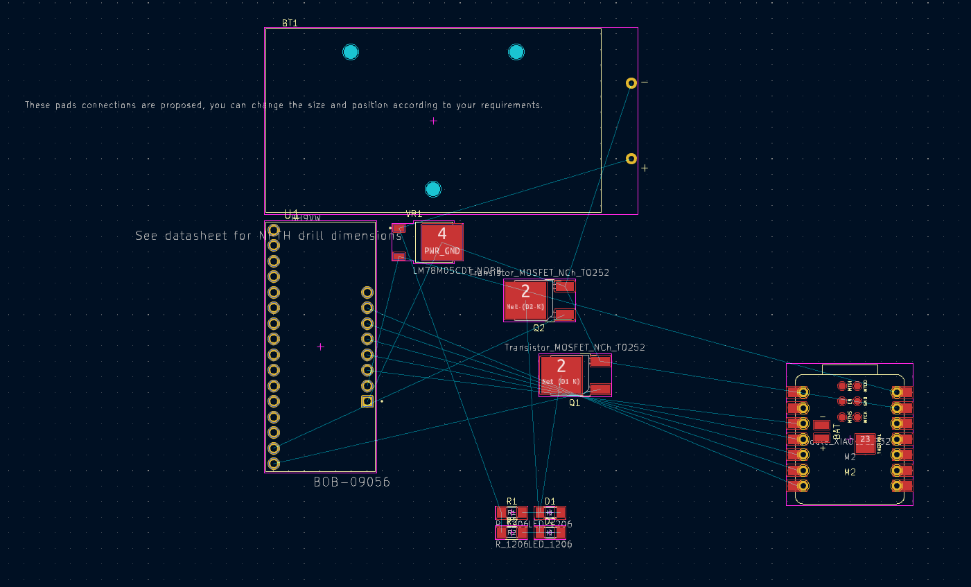
These are the components I need to arrange on my PCB. The battery holder is by far the biggest part, which should indicate how small generally all the other pieces are.
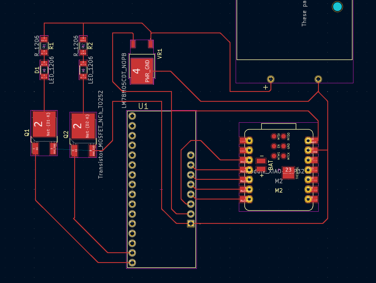
After some arrangement I can start to see how the pins between my XIAO and multiplexer are crossed. I think this is a good example of when to go back to the schematic designer to change the order of my inputs.
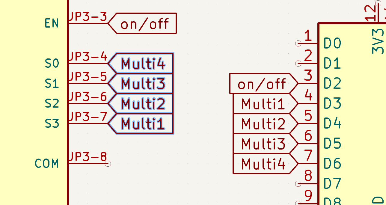
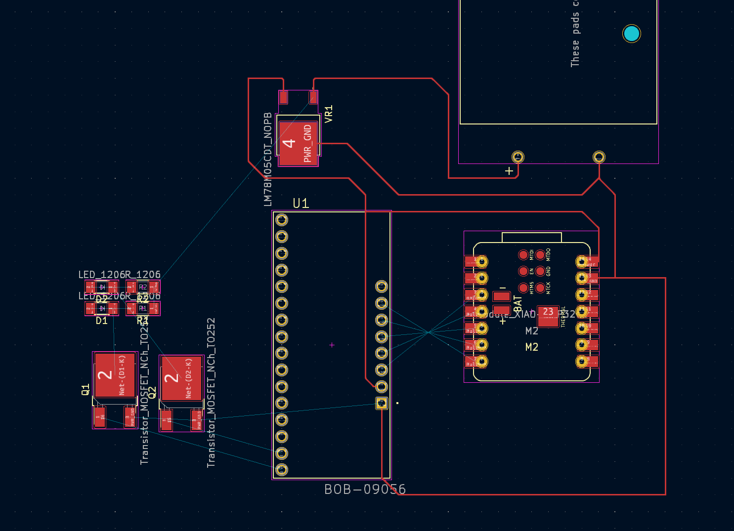
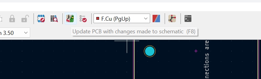
Here I switched the order of my pin connections... lets see... Make sure you save your changes in the Schematic editor before trying to update the PCB design because if not nothing will happen.
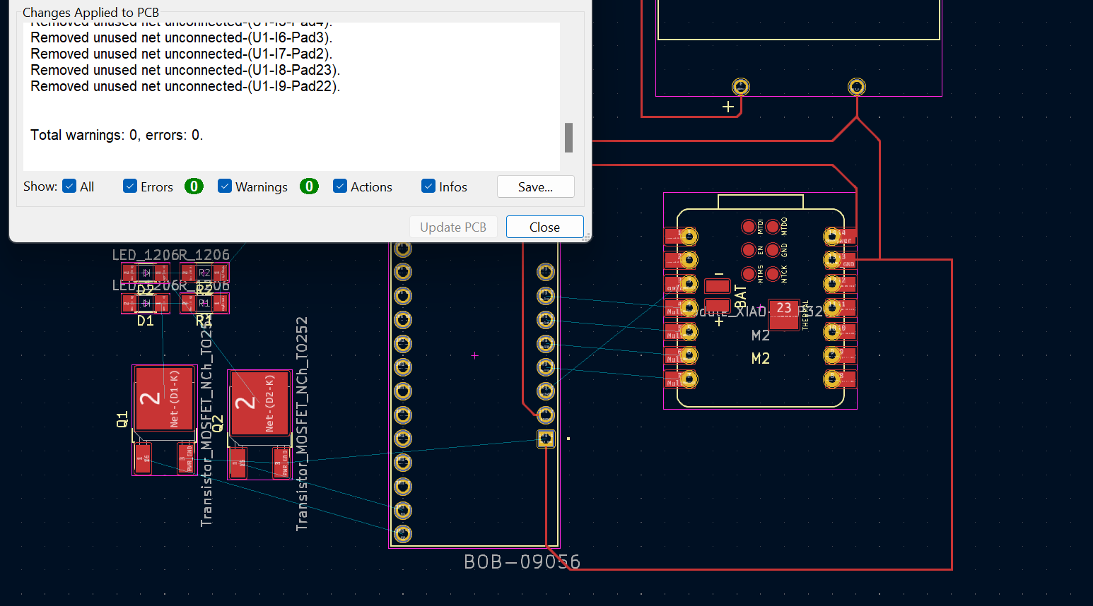
Belissimo
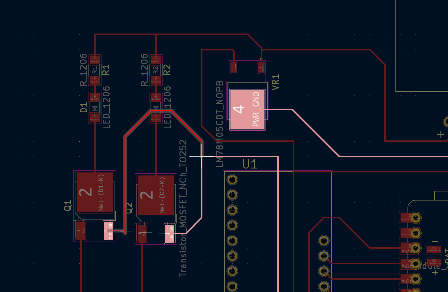
Aside from the less-than-attractive inefficiencies, there stood out to me one real issue which is that the second mosfet seems to be unable to ground, trapped in a courtyard of wires. I sorta remember something being said about the 1206 resistors and LEDS being used as bridges to get underneath... which maybe seems possible here.
I think this might work, but it becomes clear to me that I need to alter my grid snap and set some design parameters if I am going to make this clean enough to eventually mill. I also will need to find room for another 14 transistors, and potentially attach them to connectors which then can attach to an LED or spotlight instead of soldering less powerful LEDs into the circuit... But given that class is in 30 minutes, I think it marks a good stopping point for me to pick up later!