Make (design+mill+assemble) something big (~meter-scale)
Extra Credit: don't use fasteners or glue
Step 1: Design
The Design
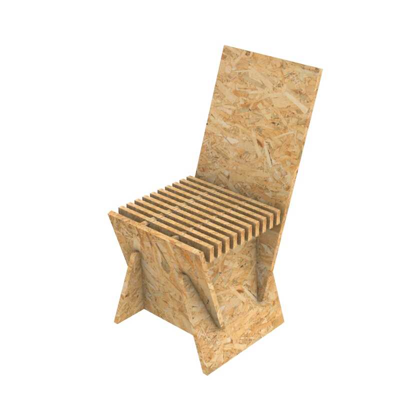
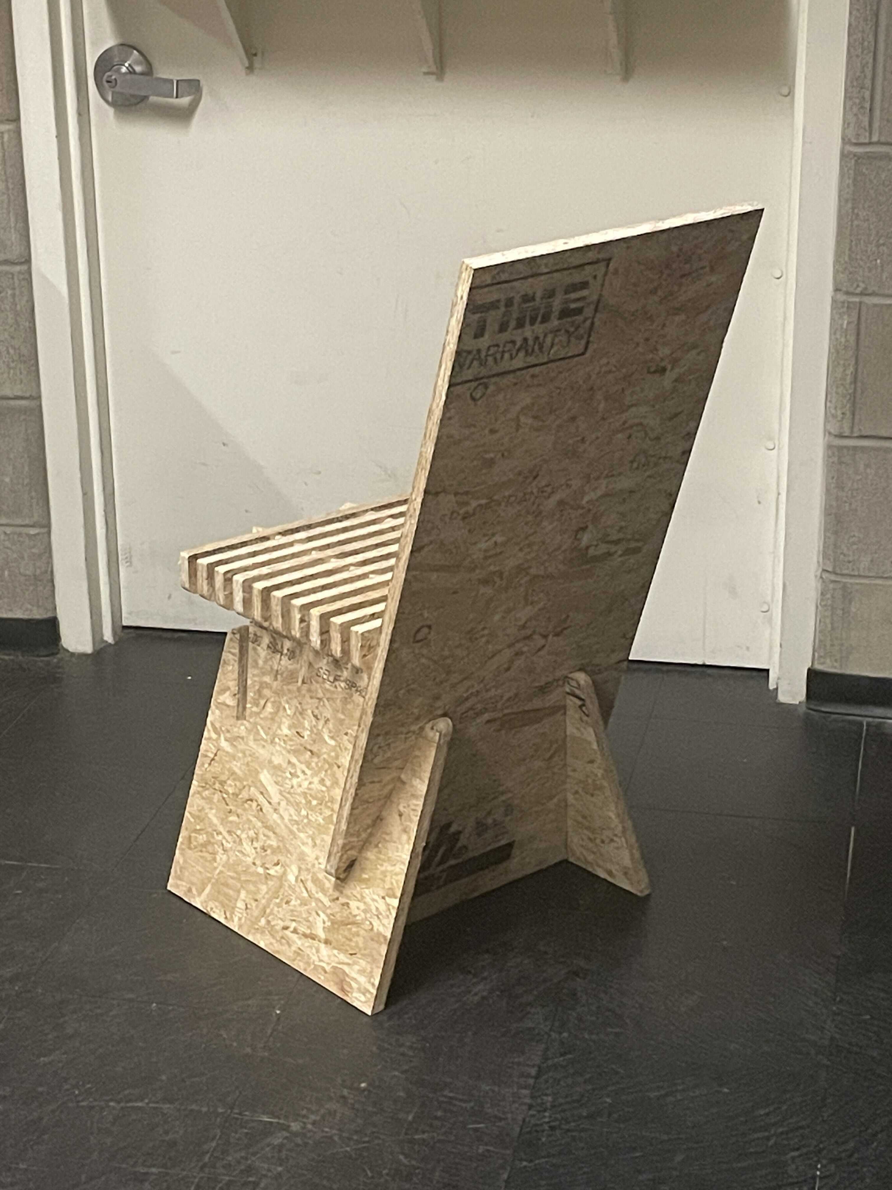
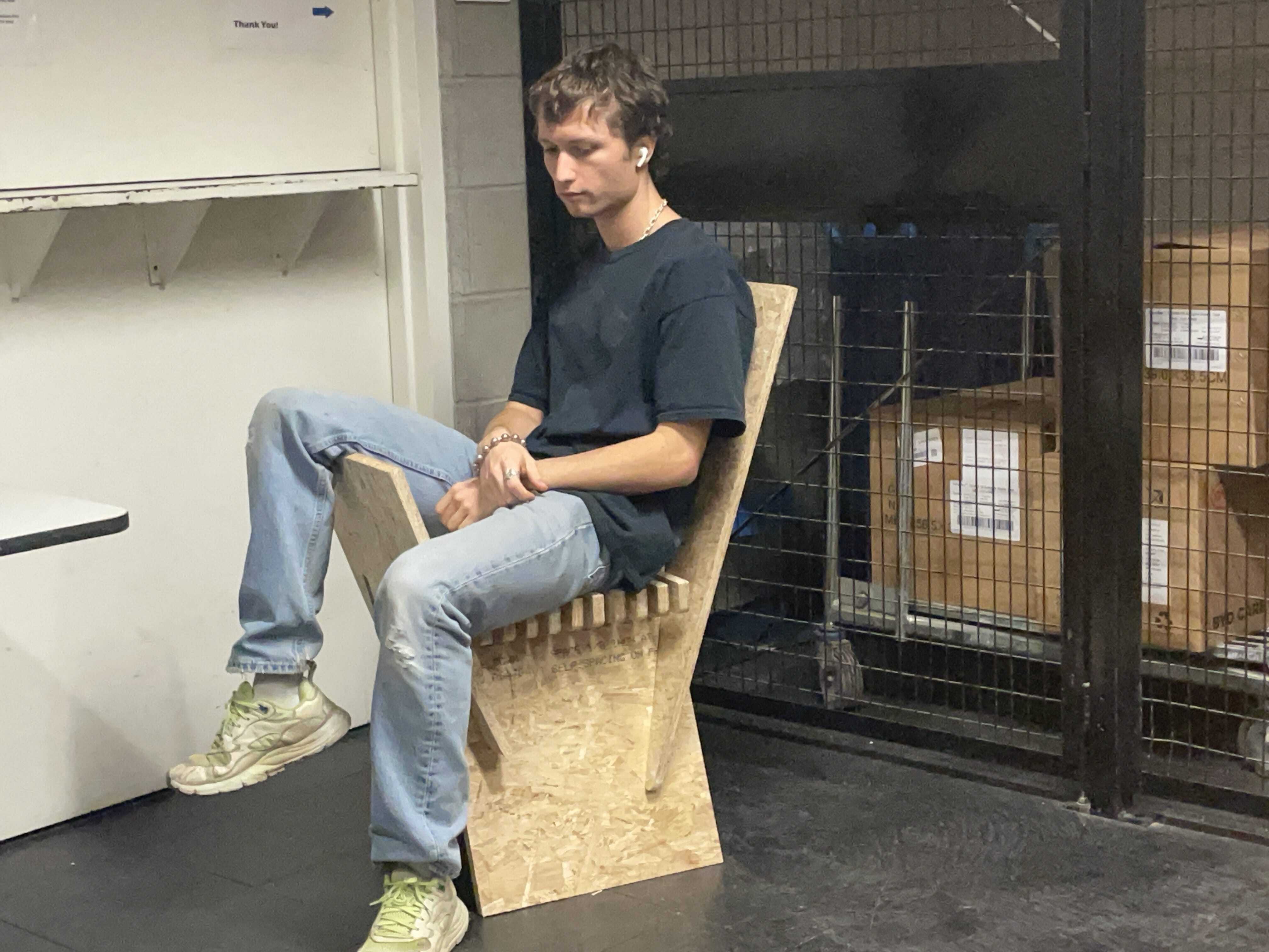
This week I wanted to fabricate a chair that I had designed a few months prior but have been avoiding prototyping because the set-up file is such a headache! Now I have school as an alibi to force me into doing it. The challenging aspect of this design is that there are two sets of planes tilting, so that their boolean intersection is rhomboidal. This causes an overhang, which would ideally be fixed by using a 5-axis mill, but given that I don't have one of these at my disposal, I have to try and set up a flip mill. The goal of this design is to use press joints to bring the geometry together, and use the tilt of the planes + weight of the body to create a moment connection that locks the pieces into place without glue.
The Layout
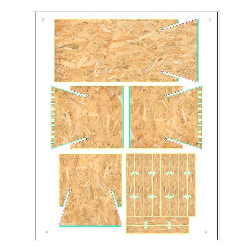
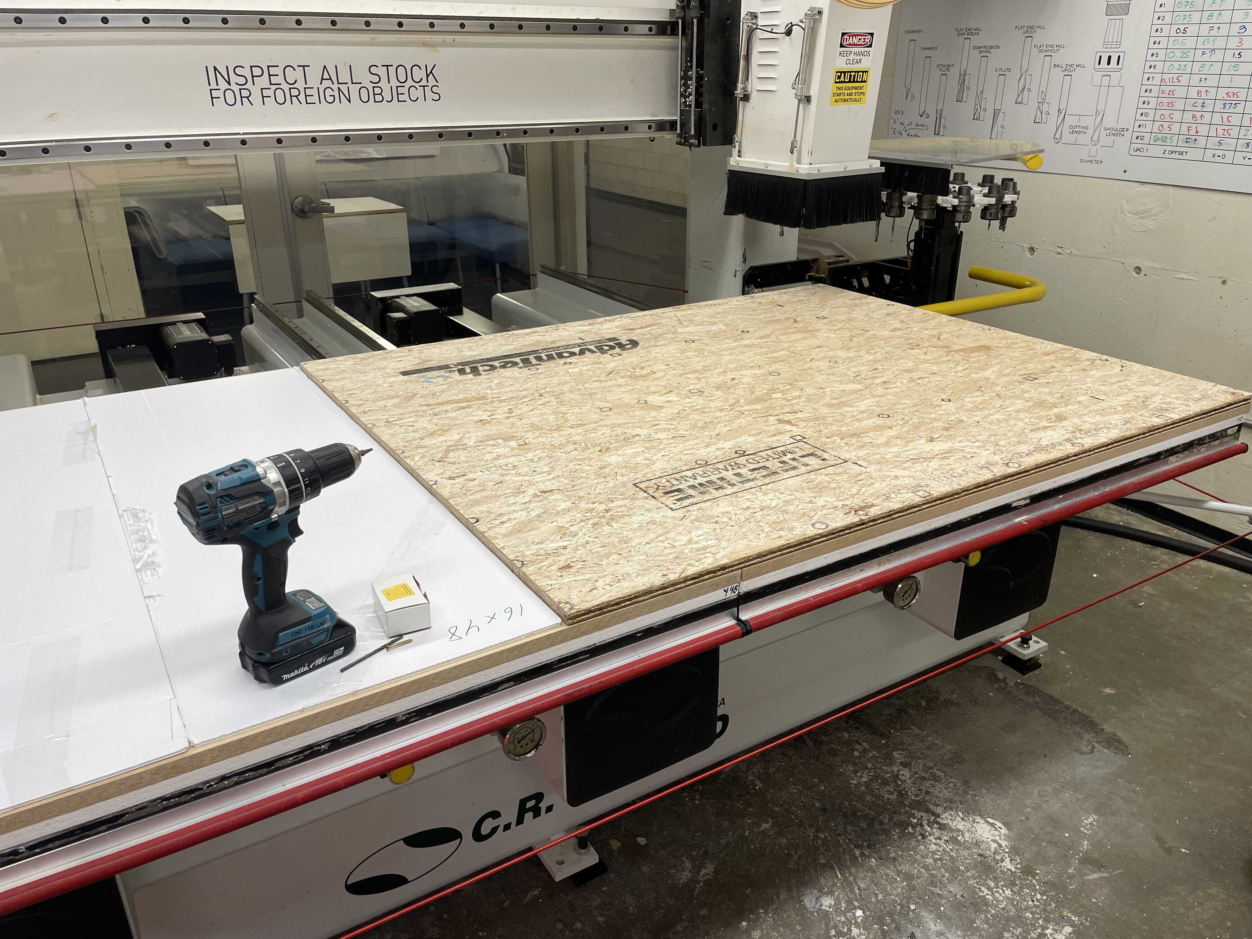
I arranged to have it cut on a leftover piece of wood I had, about 48x59". You need to included additional surface area for a flip mill so that the guide holes can be drilled in both your stock material, and the sacrificial board.
The Original Toolpath Sequence
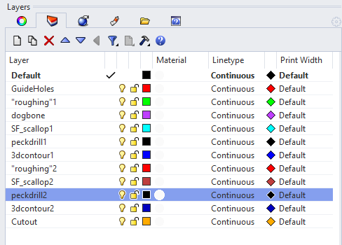
These are the layers I have set up in my Rhino file. GuideHoles is a layer containing four points, which will serve as the geometry MasterCam uses to register one piece of wood to the other, so that when you flip it upside down, it remains in the coordinate box. It uses a drill operation with a ball-nose tool to remove a hemisphere from the surface of the material. Another hemisphere will be removed from the sacrificial board in the same locations. A .5" ball-bearing will be placed in the depression, and will slot perfectly into the flipped stock. My "roughing" operations are not actually roughing toolpaths, they are 2D contour toolpaths using a 1/4" compression spiral that will ramp in around the slightly slanting surfaces, clearing away the surrounding material. This allows another toolpath to come in (Surface Finish Contour [labelled SF_scallop in this image]) and produce that slight tilt. The dogbone layer is what it sounds like, used on all interior corners of my orthogonal pieces. The 3dcontour and peckdrill layers are also for dogboning the press joints, but used on the non-orthogonal press joints. The number2 variants of each layer is simply the same operations being cut on the flipside of the material. And lastly you cut each piece out.
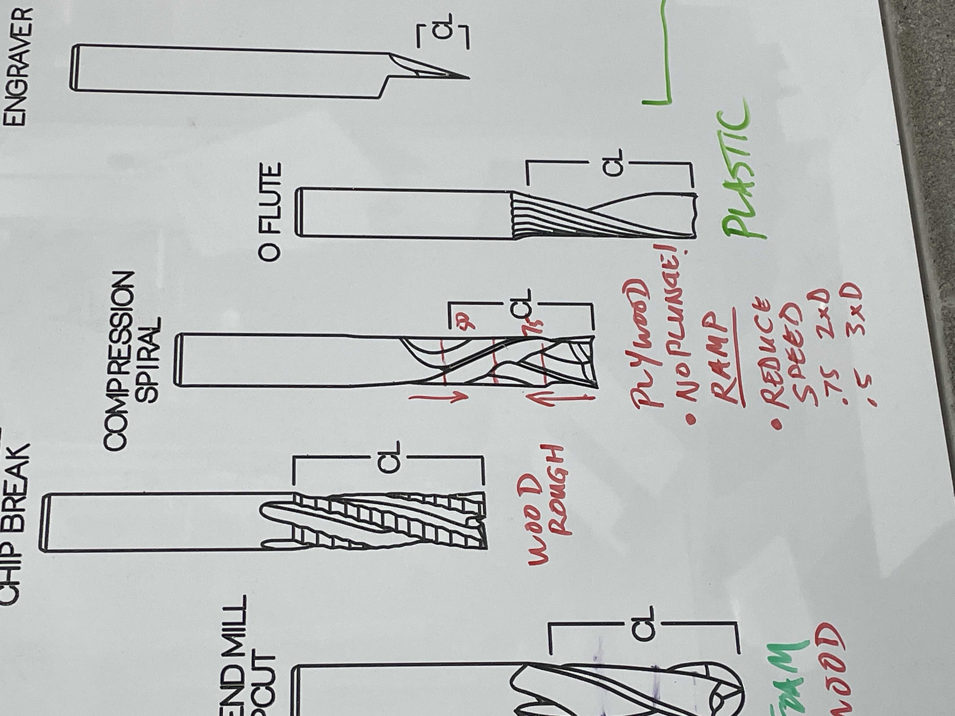
Compression Spiral
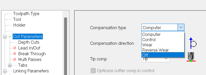
Compensation Direction Mastercam
Contour tolerances accounted for in rhino
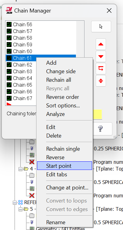
To prevent gauging, needs ramp in. Some geometries require you to change the entry point of the tool so that the ramp-in doesn't run through material you want to keep intact.
Strategy looks like this
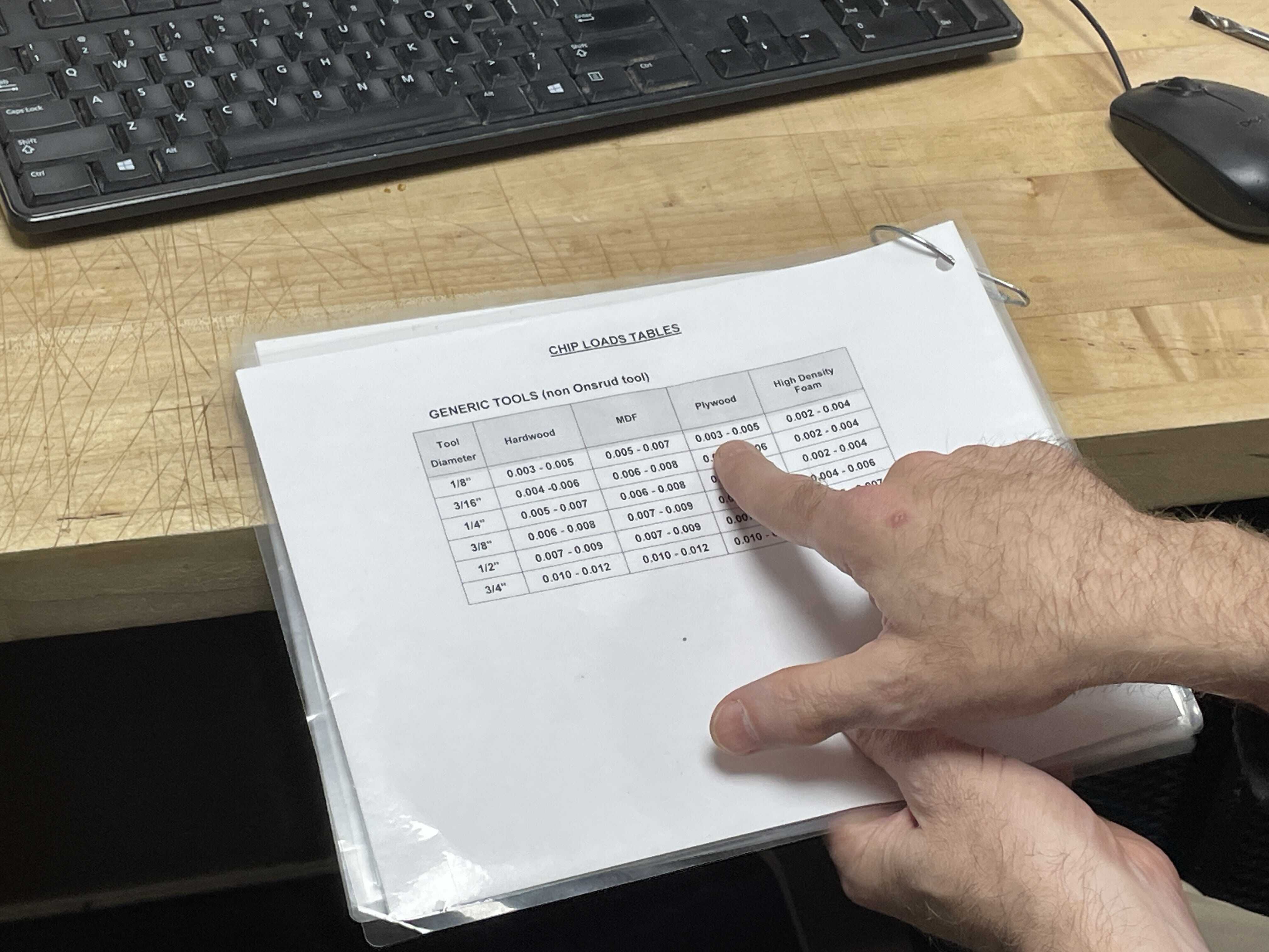
Cheeck feedrates based on what material / size tool you are using. Update the toolpath parameters in MasterCam to reflect this.
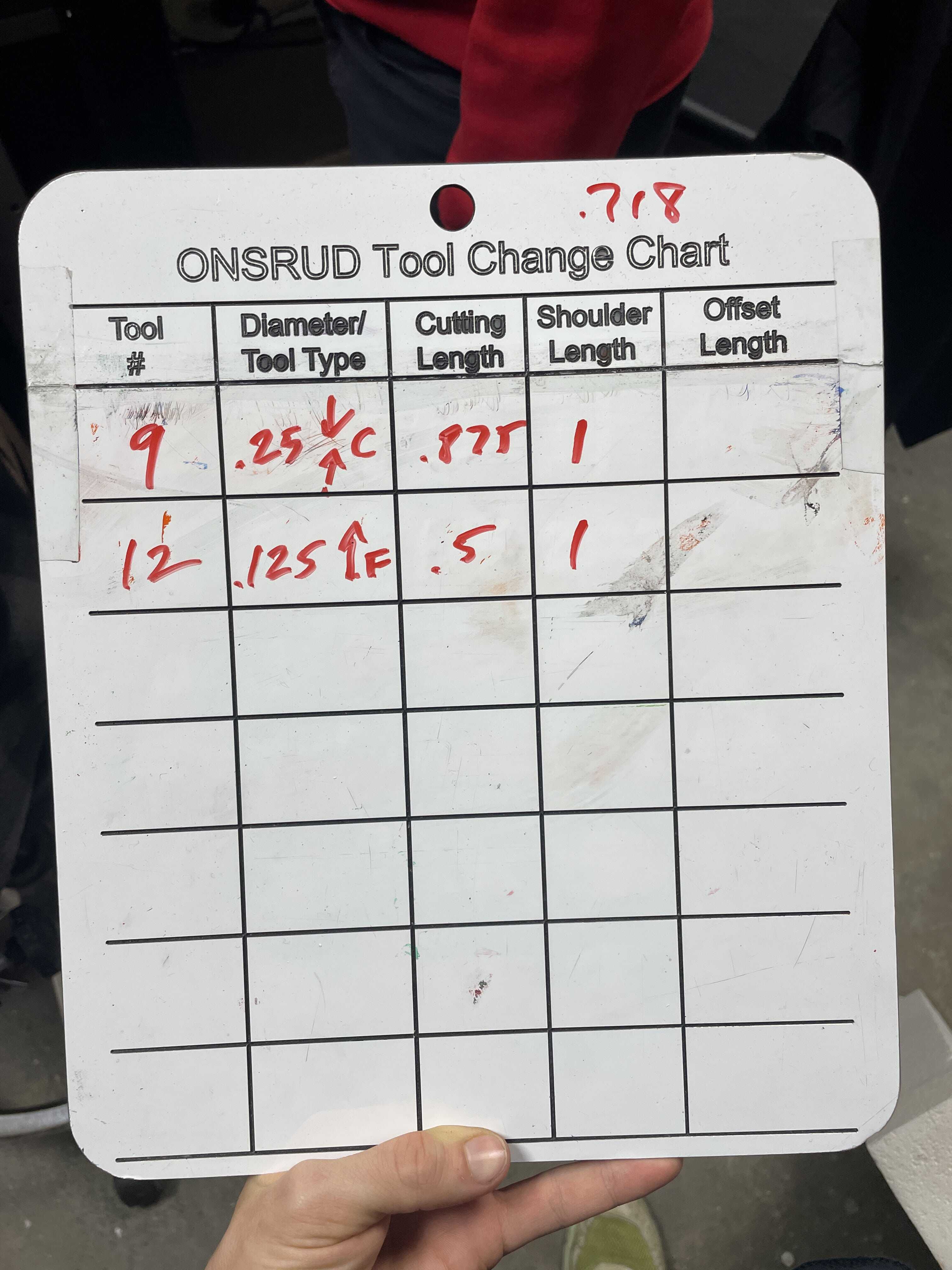
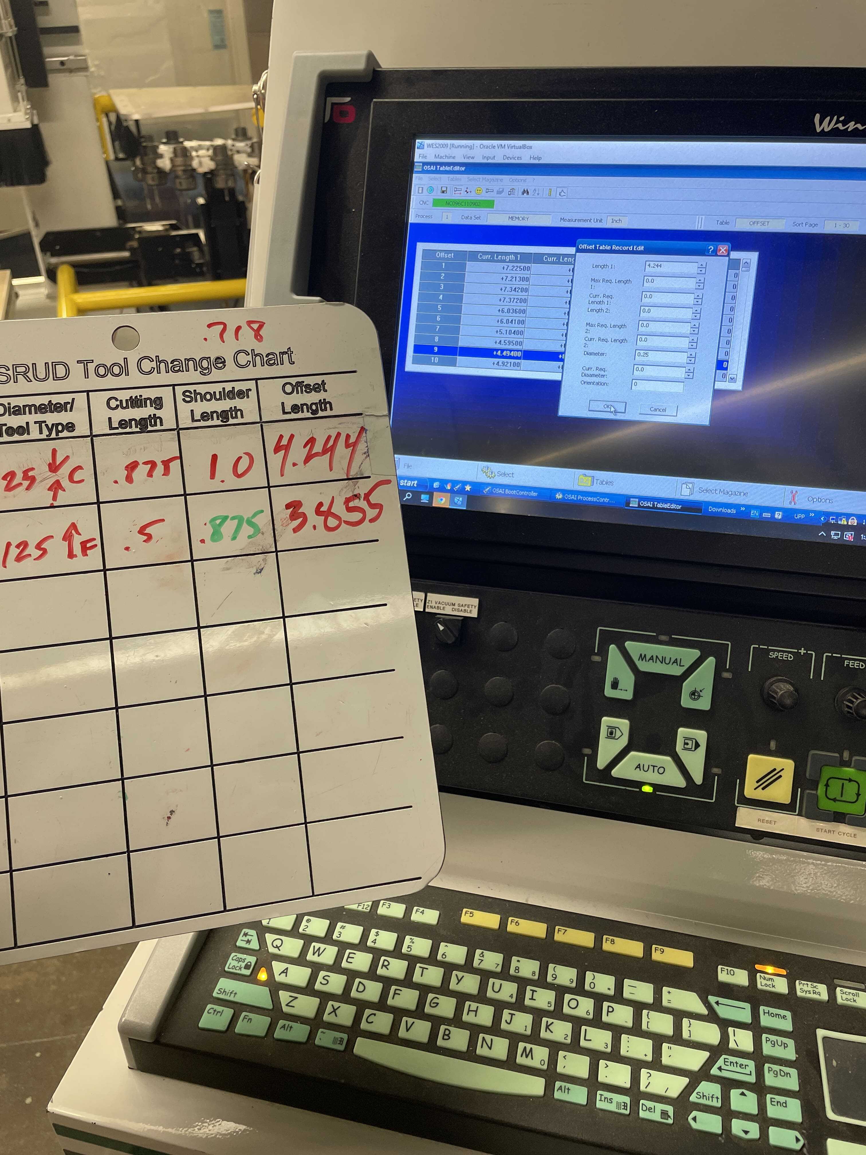
Measure the tools and update the toolpath parameters to reflect their distances. This is needed to check for any potential collisions.
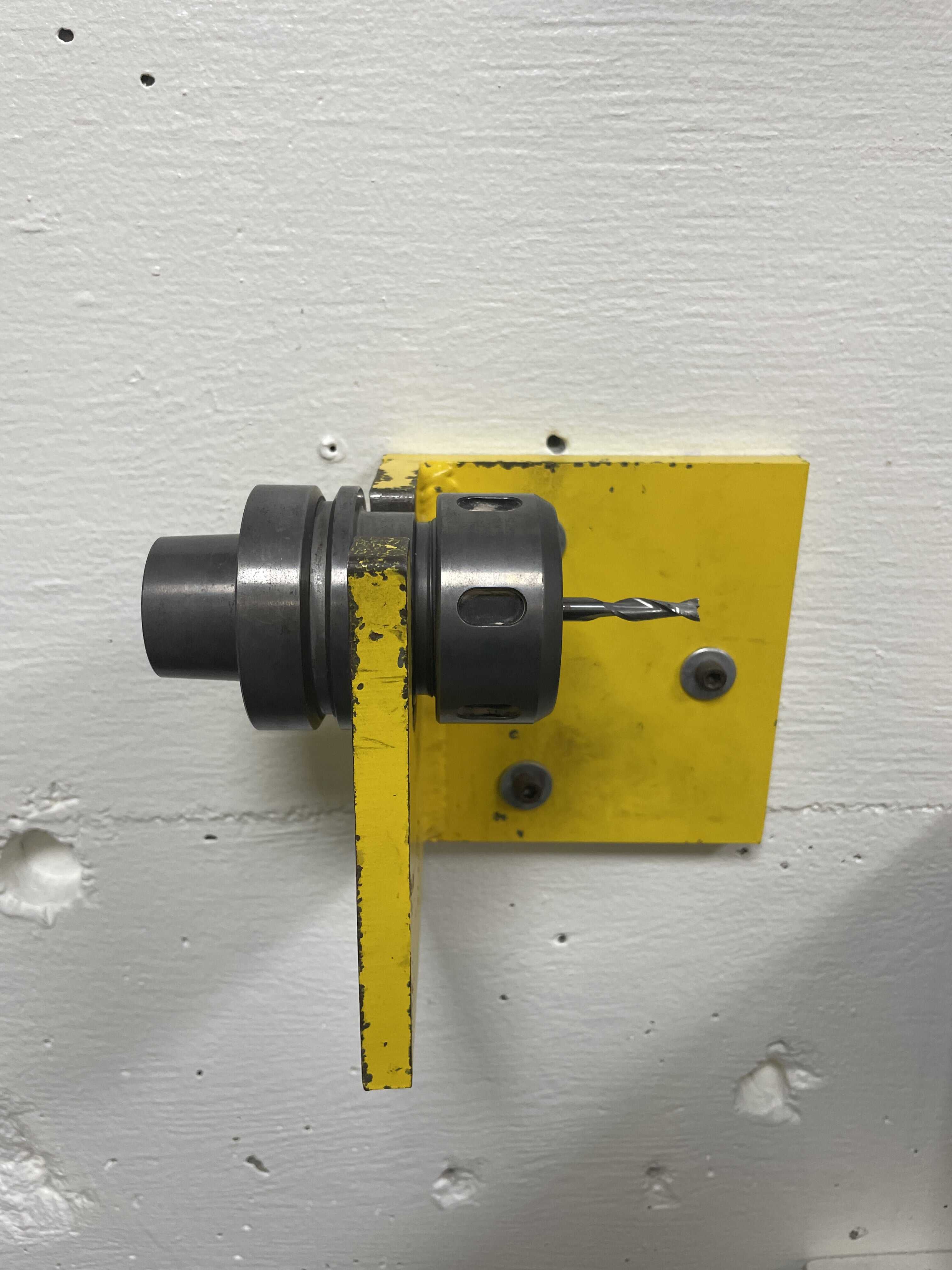
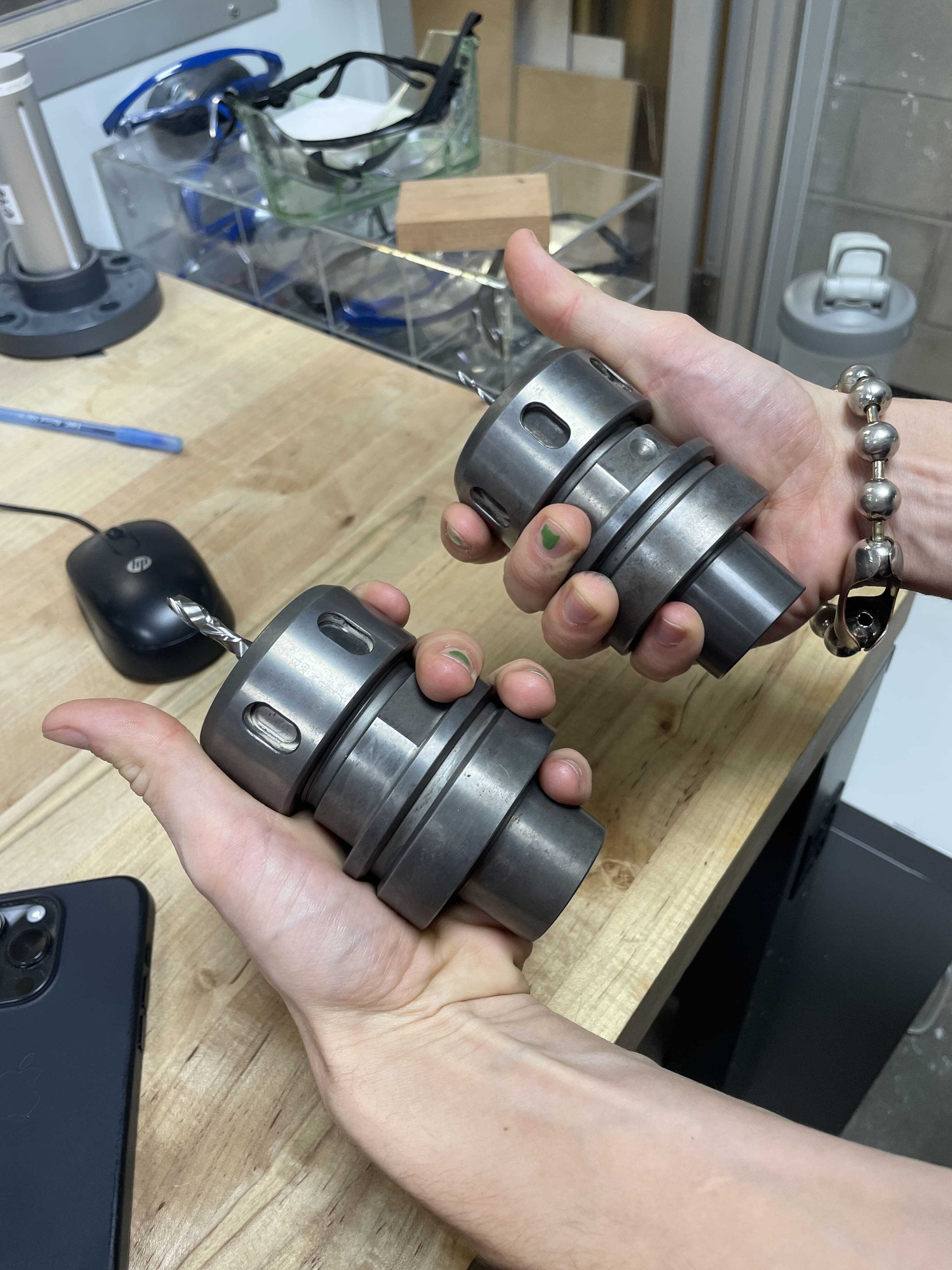
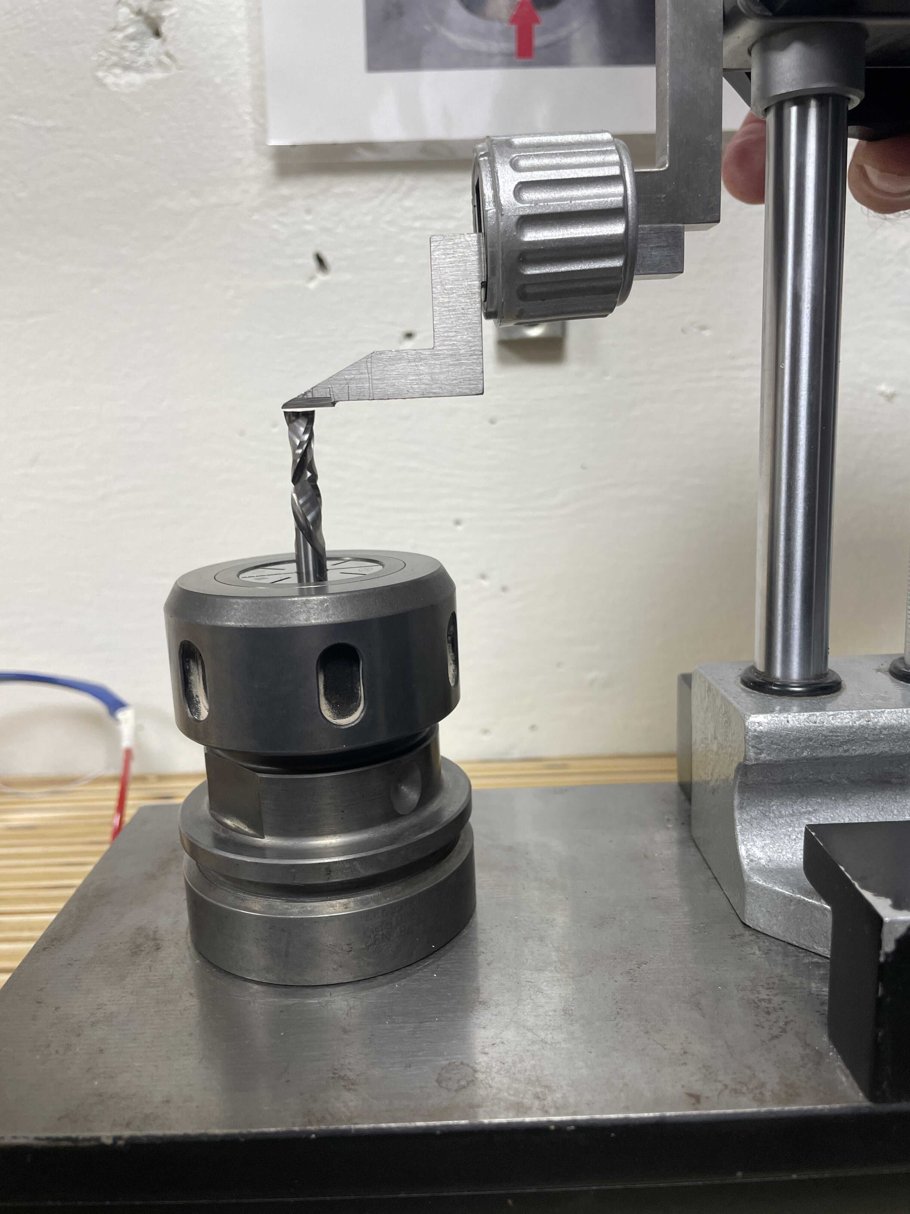
Go grab the collet from the machine and prepare to change it to the correct bit. Place facing right to loosen, place facing left to tighten.
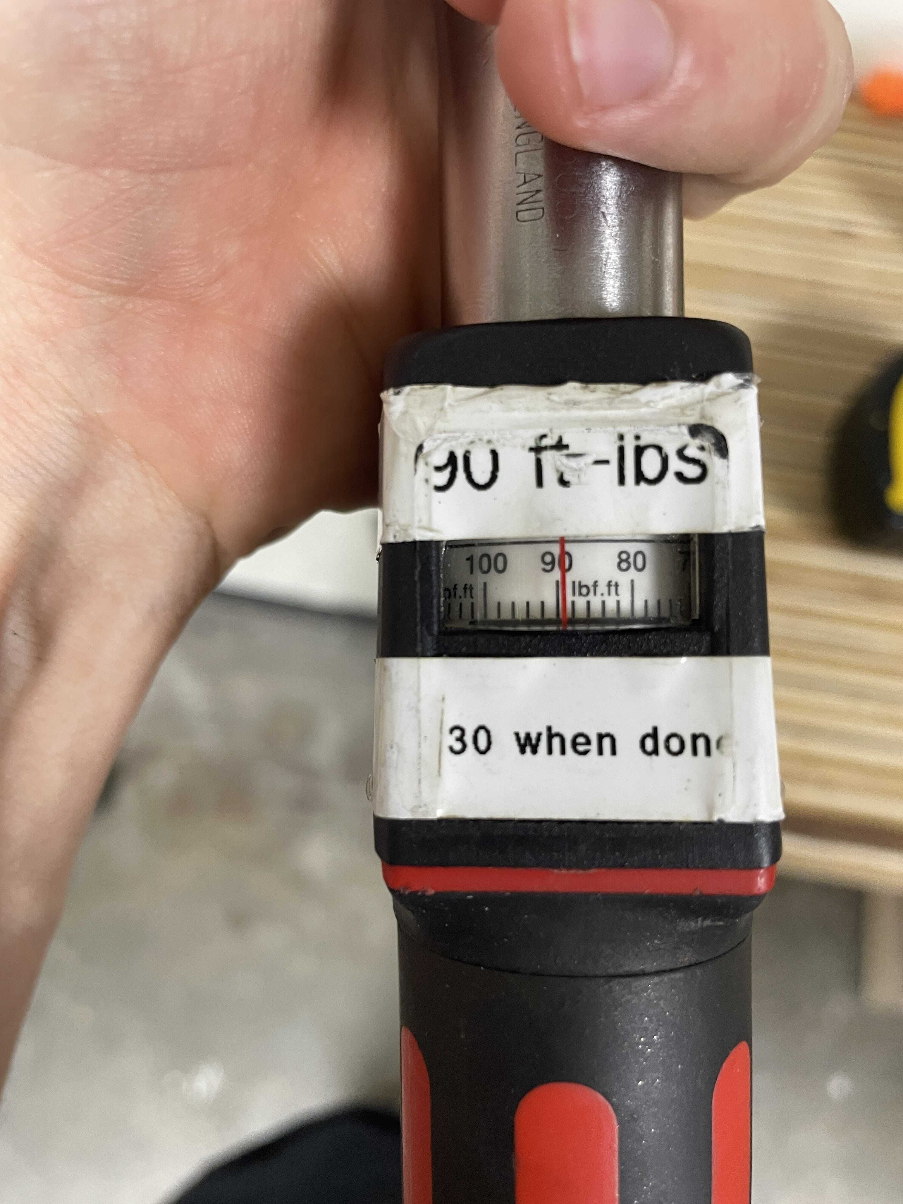
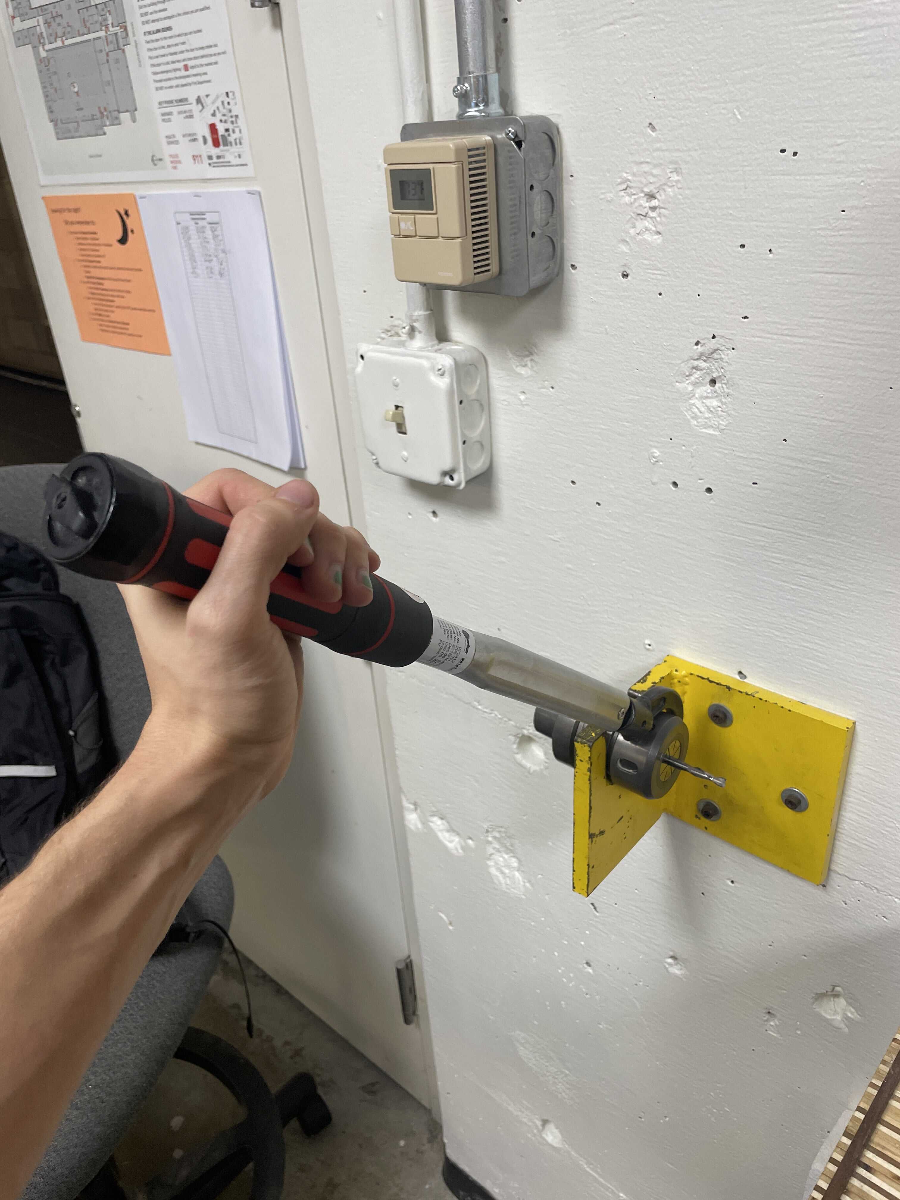
Set torque wrench to 90 ft-lbs
Crank that baby
Place facing left to tighten.
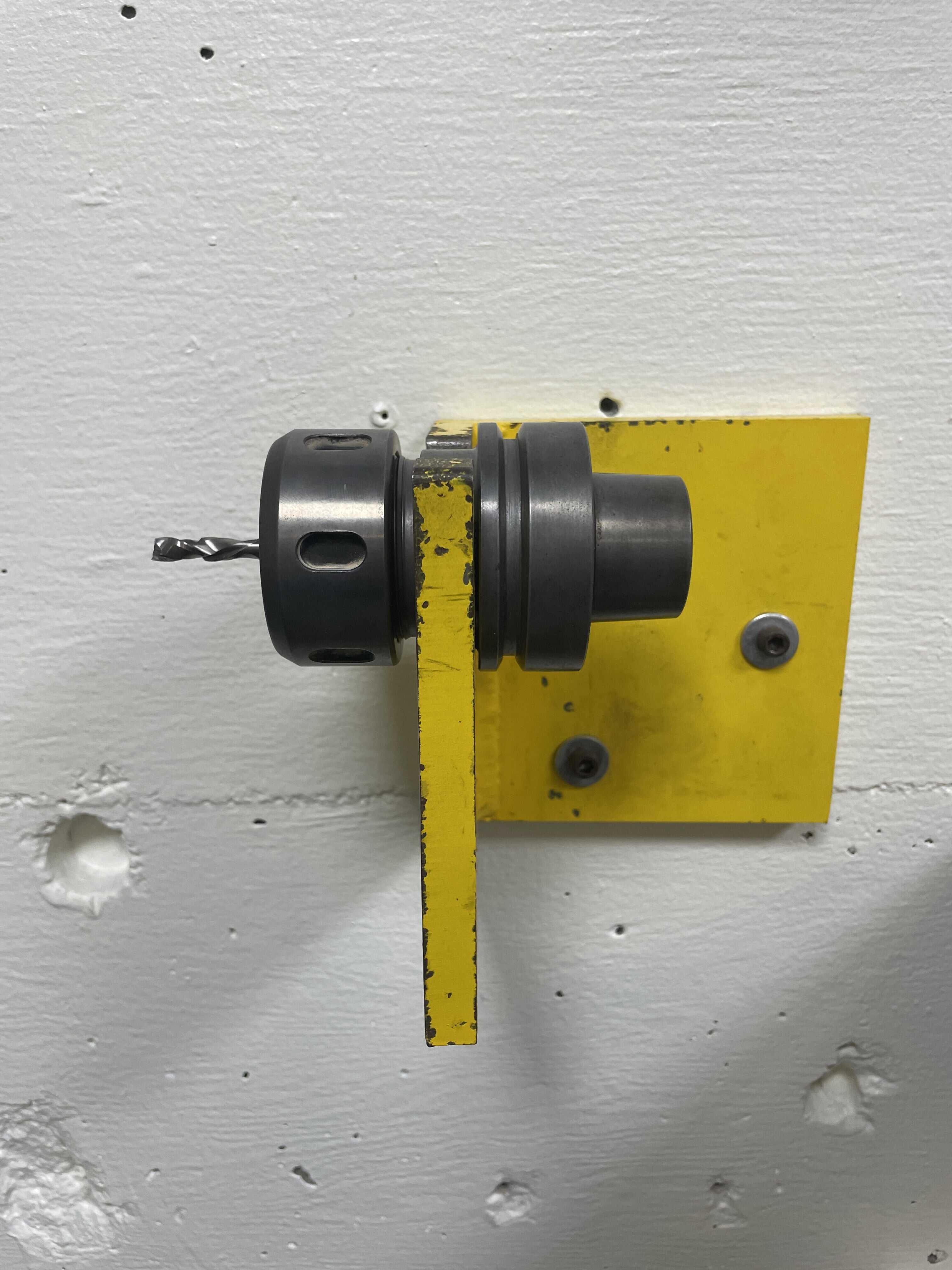
All set!
Super important to now measure shoulder length. You will need to tell the computer running the machine (not a part of the gcode) this distance.
This is how you measure it, you need one of these precise tools
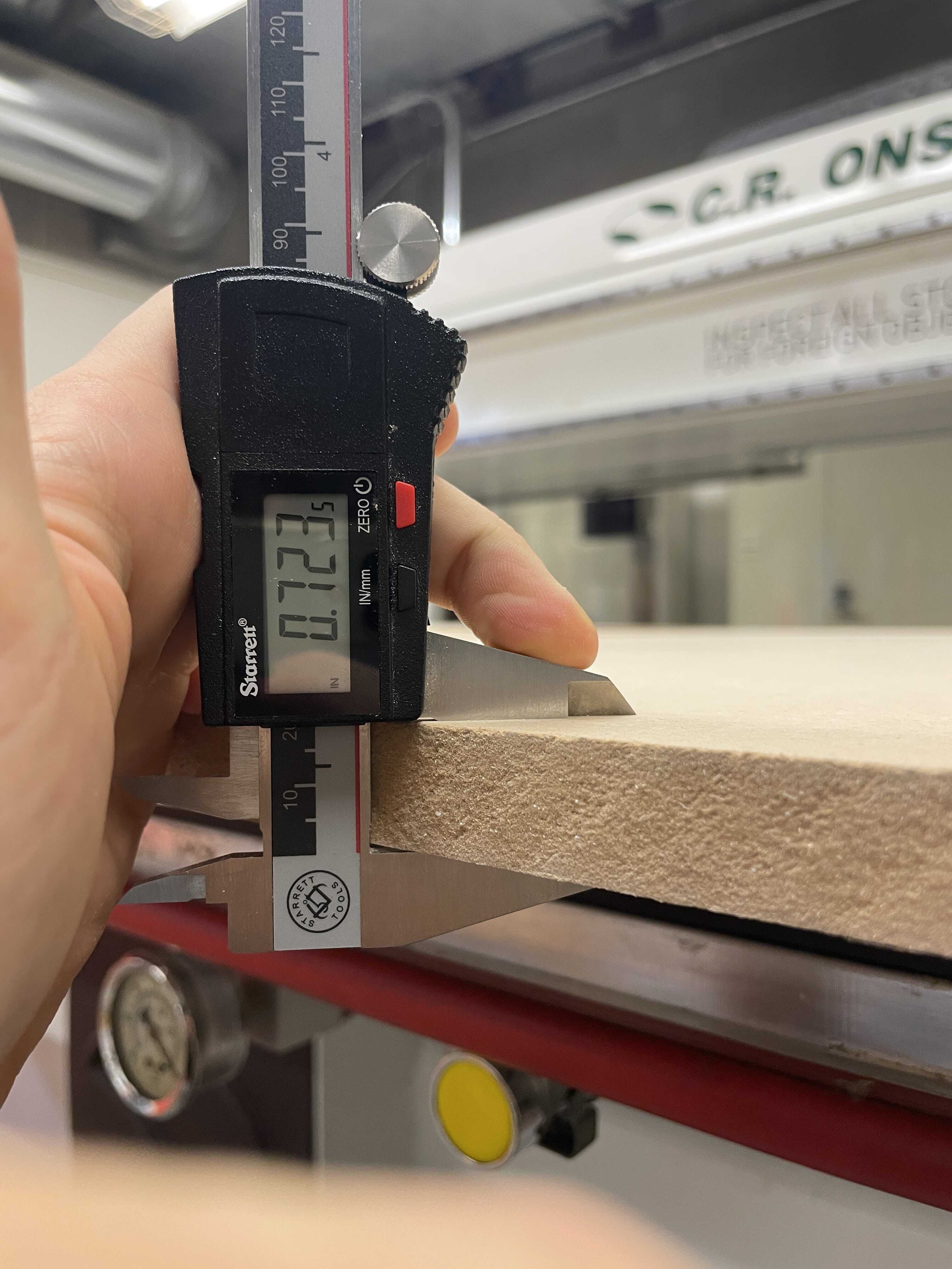
Measure your sacrifical board thickness, will have to account for this in the z-height calibration.
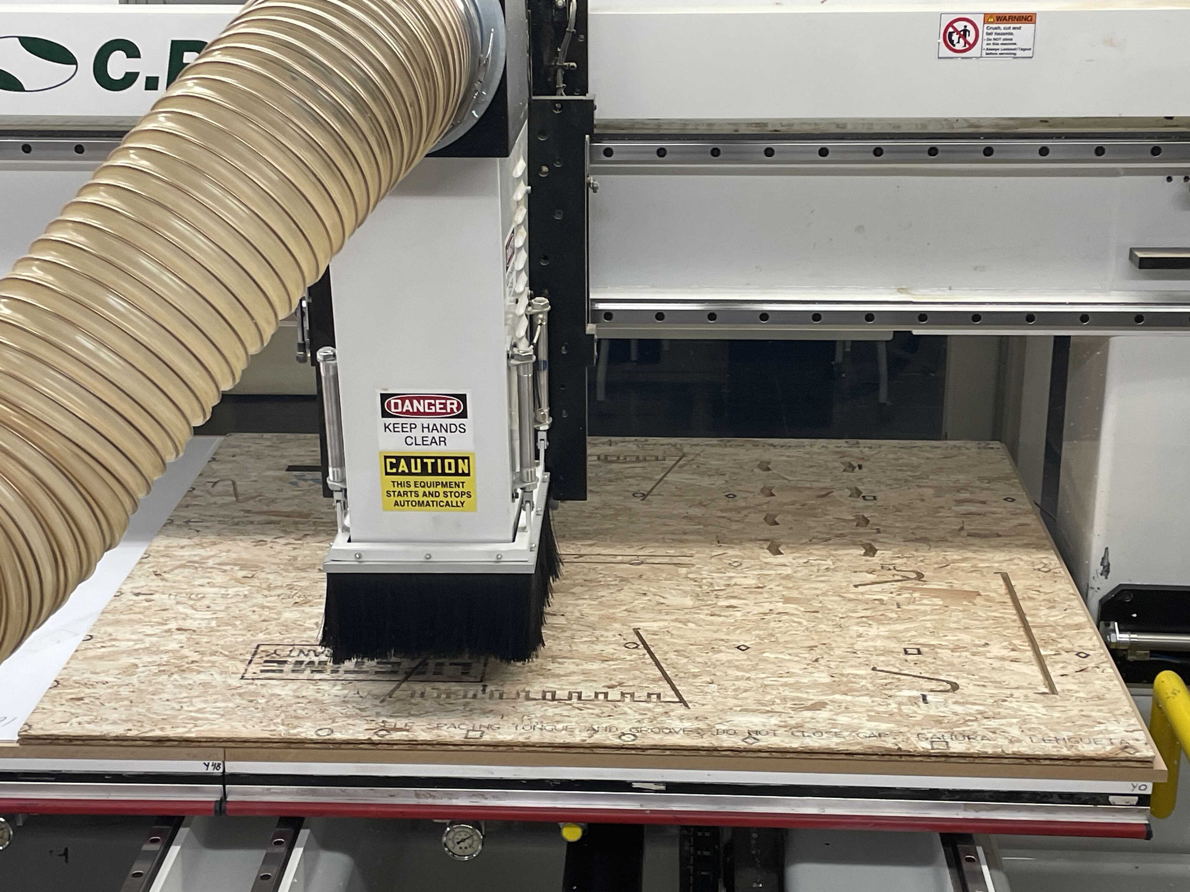
So luckily the vacuum table is pretty solid even through the additional spoil board, no need for screws here. Will do on the otherside to ensure it holds down as holes start to cut the board into smaller pieces.
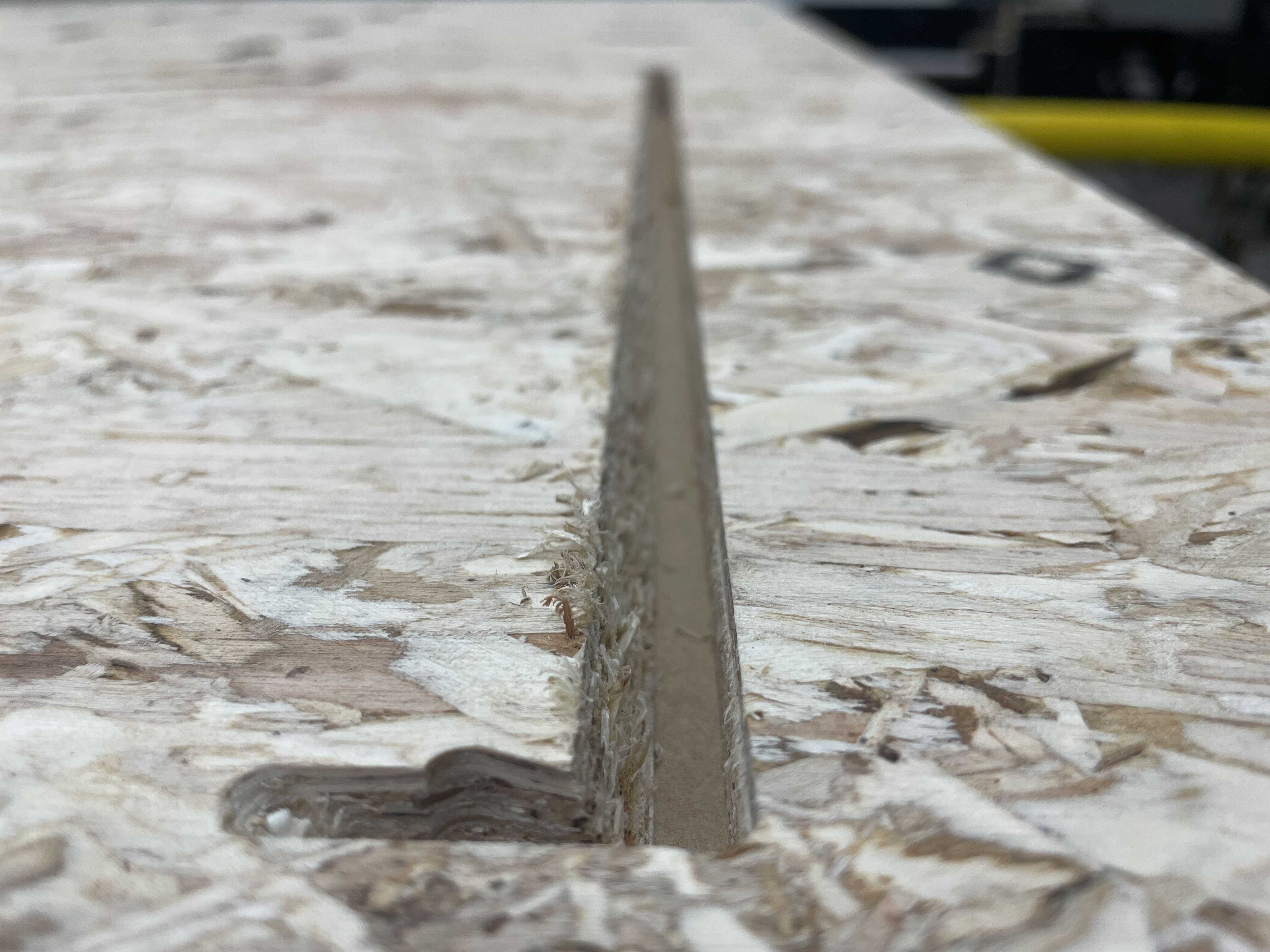
The angled surfaces are coming out nicely
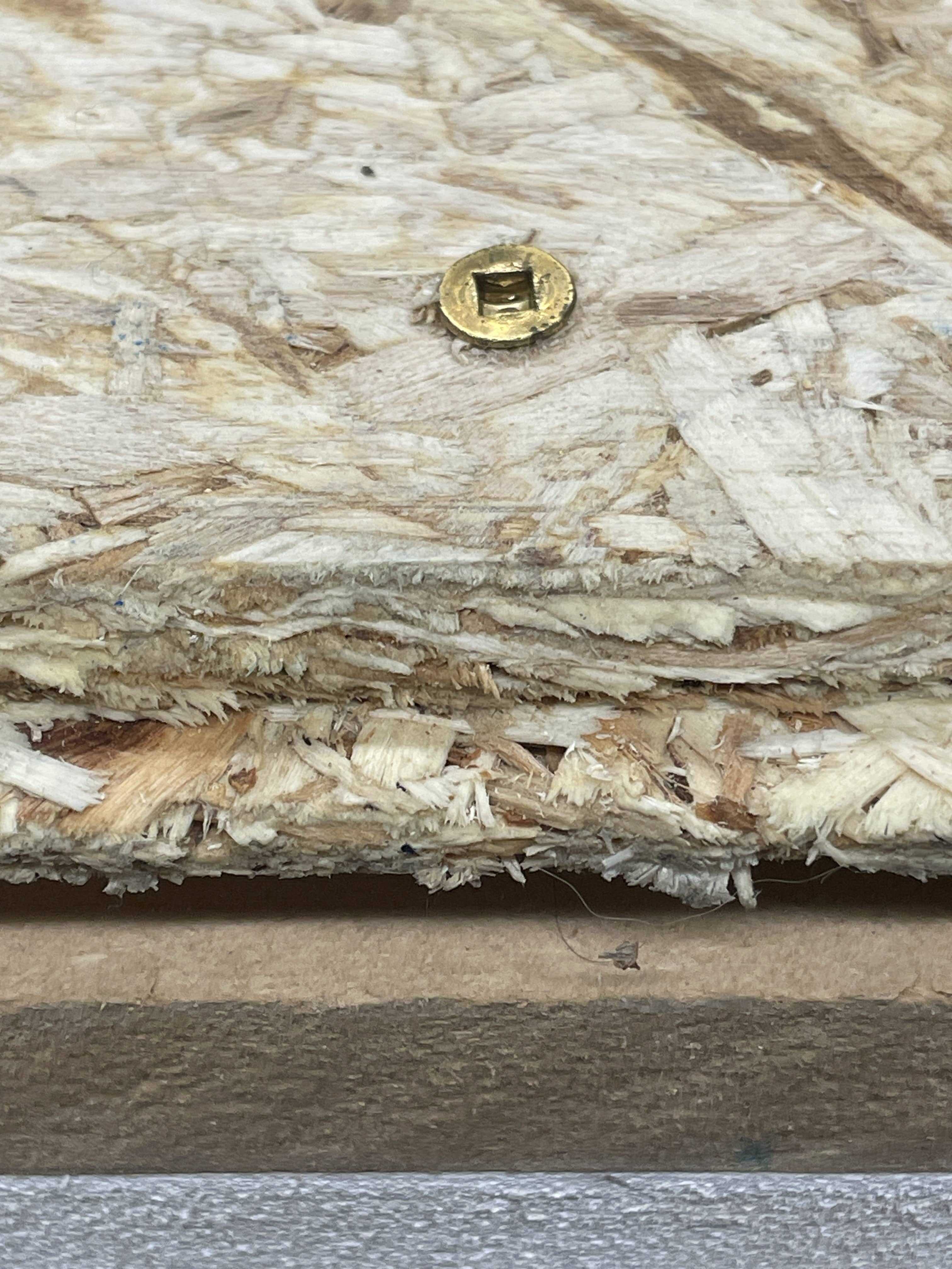
added screws for flip side
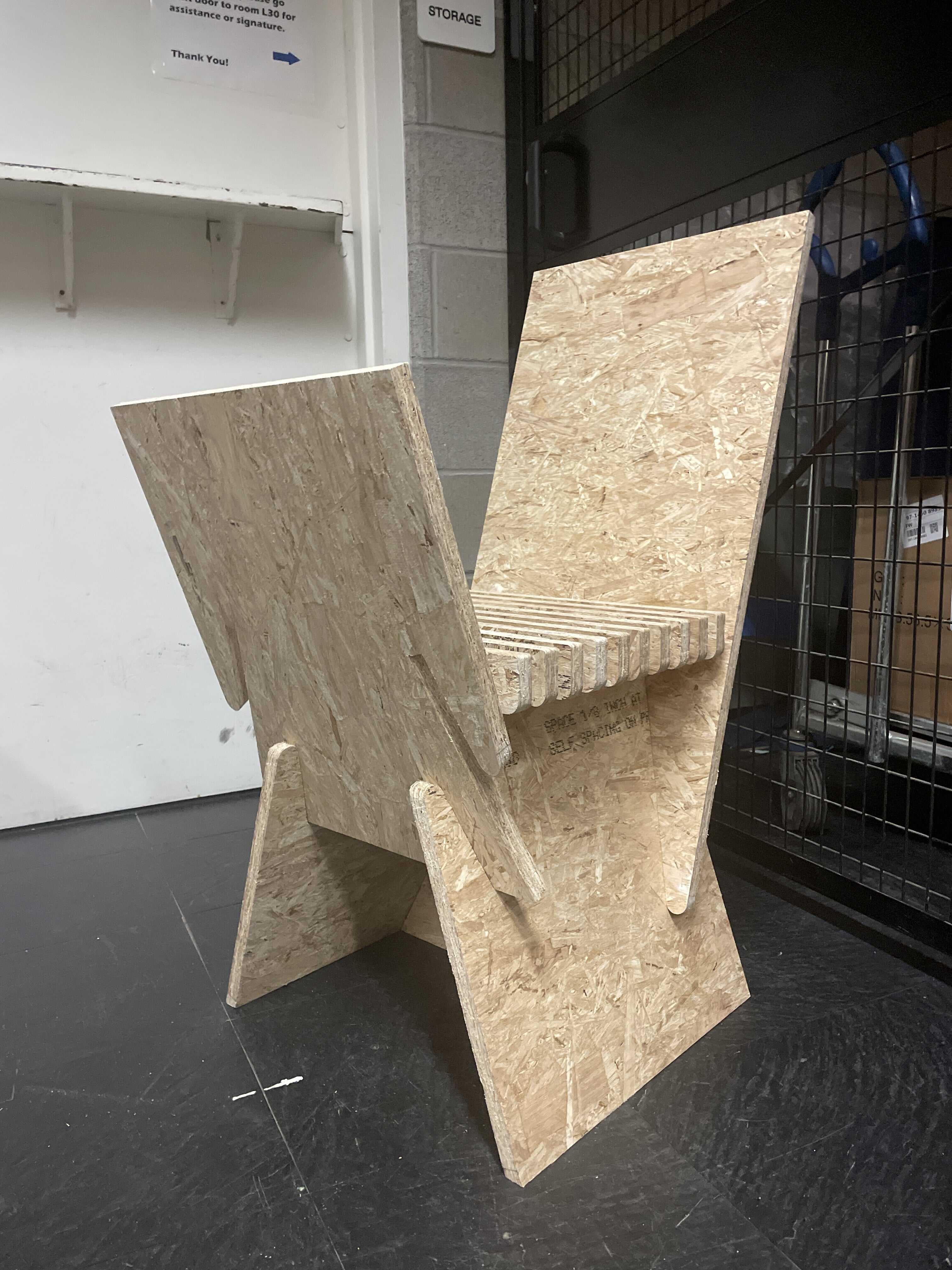
Everything cut perfect! The tolerances work pretty great, and it slides together super easy. Only one problem... lmao embarrassing
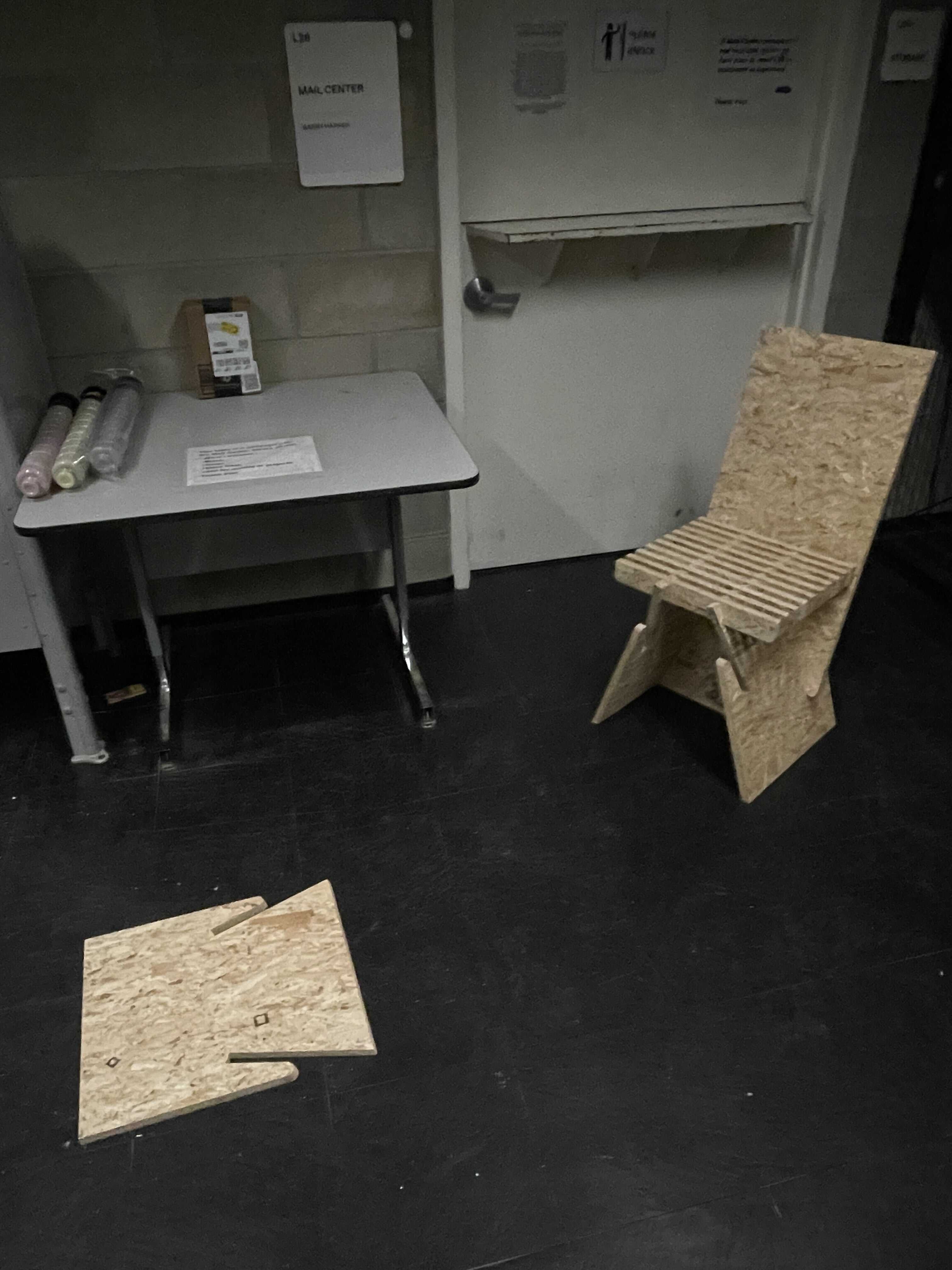
There is no particular assembly order but no matter what the last piece is it will not fit. Based on the geometry of the joints its just topologically impossible. Facepalm
So close lol
The last piece actually needs to be broken into two pieces. This is how I'm planning on fixing the design. One piece will a left edge that is parallel with its joint, this will have to be placed second, since it will be able to slide into place. The two pieces will overlap a couple inches, and some kind of pin will need to piece between them to make it completely rigid. Guess this is why you prototype things lol
I remodelled that front piece as two pieces, with a 2" overlapping joint, and 5 centered peg-holes piercing between them. I added it to the same size flip-mill file because it was able to fit, and yolo why not make another chair if I'm going to spend the time running another file.
So in order to accomplish this geometry, I just had to add two roughing passes, one from each side of the flip, which removes material equal to 50% of the stock thickness. I also added a peck drill operation for the peg-holes. Many of these toolpaths ended up need containment curves, which force a toolpath to stay within a boundary when its generating its protocol. The layers shown on the right here are the final compilation, this is what it takes to run this job. Reminder that "roughing" isn't actually a roughing command, its a 2D contour toolpath. The last file was able to run with only two tools. This file will need make end up using a different tool for the added roughing toolpaths. But maybe the compression spiral could just do this too, when in doubt ask an expert.
This is the 3dprint I designed to pin together the two pieces.