Assignment Prompt:
Add an output device to a microcontroller board you've designed, and program it to do somethingStep 1: Design
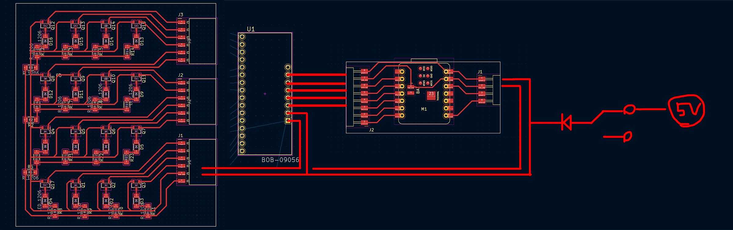
In a previous week I had designed this 4x4 LED breakout board that I hadn't yet gotten a chance to finish fabricating / testing. It's an interim design for my final project, so I figured this was a good time to pick up where I left off.
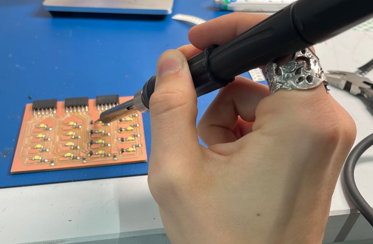
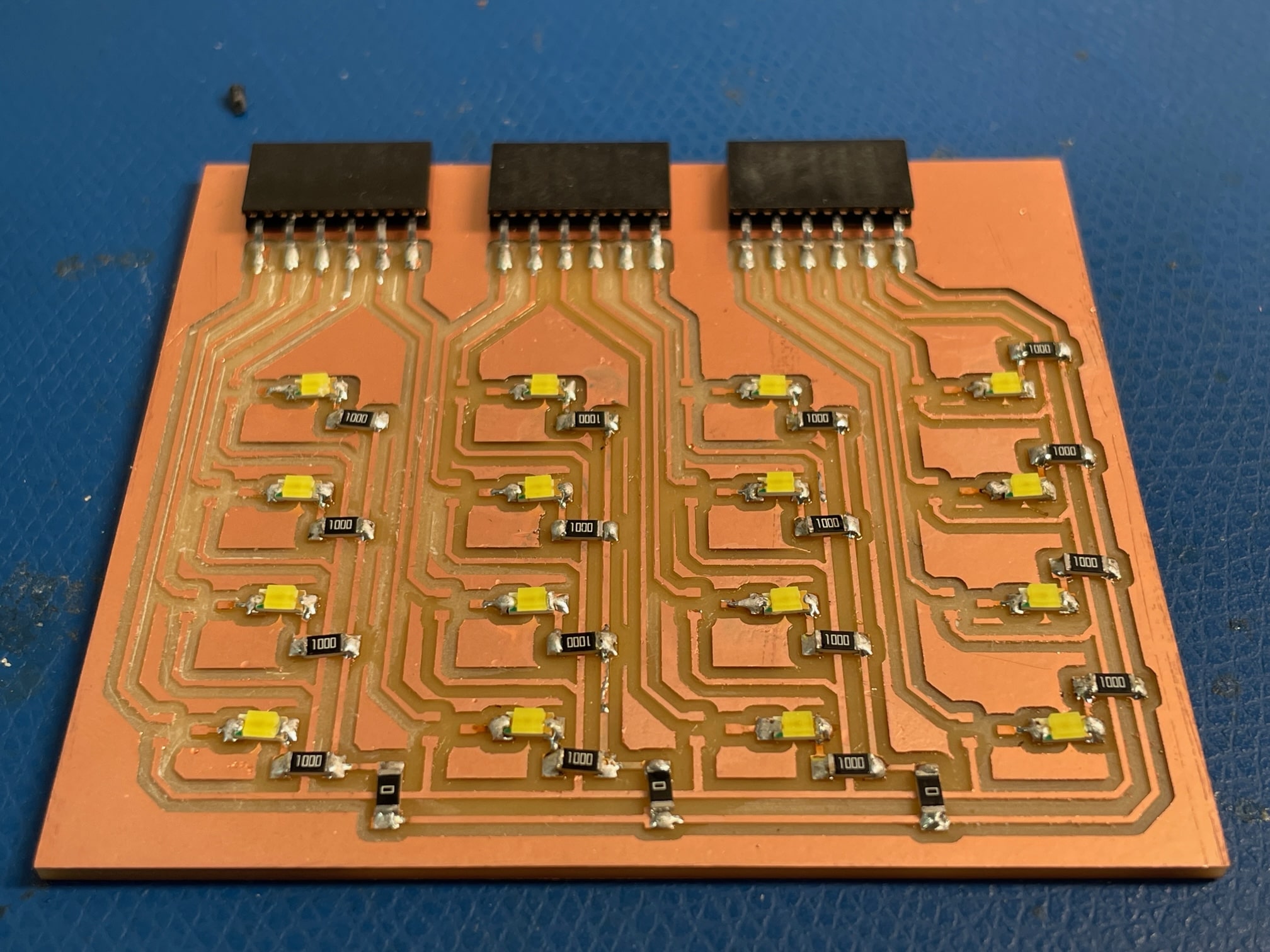
I remilled, which went fine, and started to get into soldering rather small things. 16 LEDS, 16 MOSFETS, 19 Resistors. Took 3 hours lol.
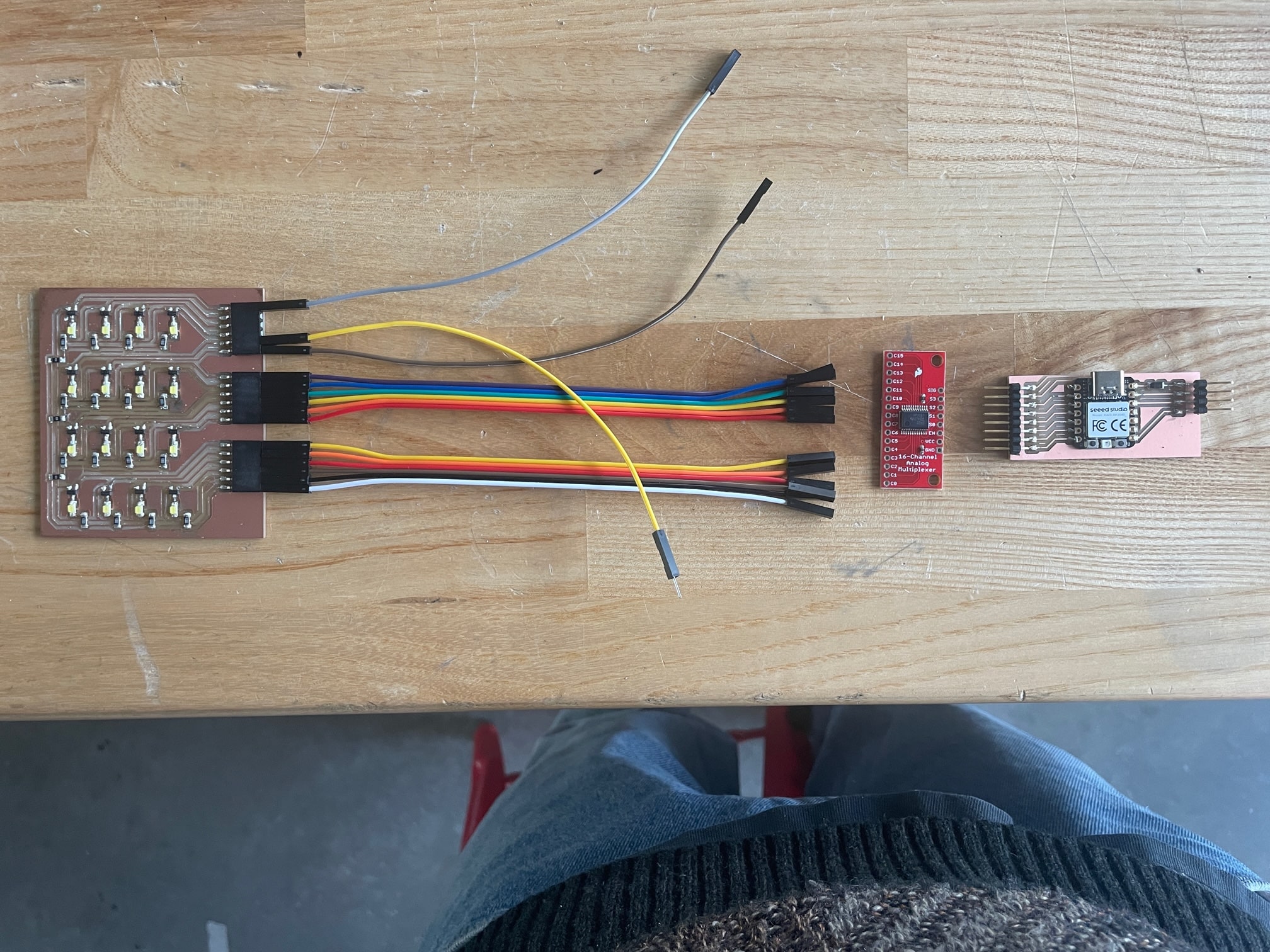
All the pieces of the puzzle are just about there... just need to get my hands on the right wires for connection...
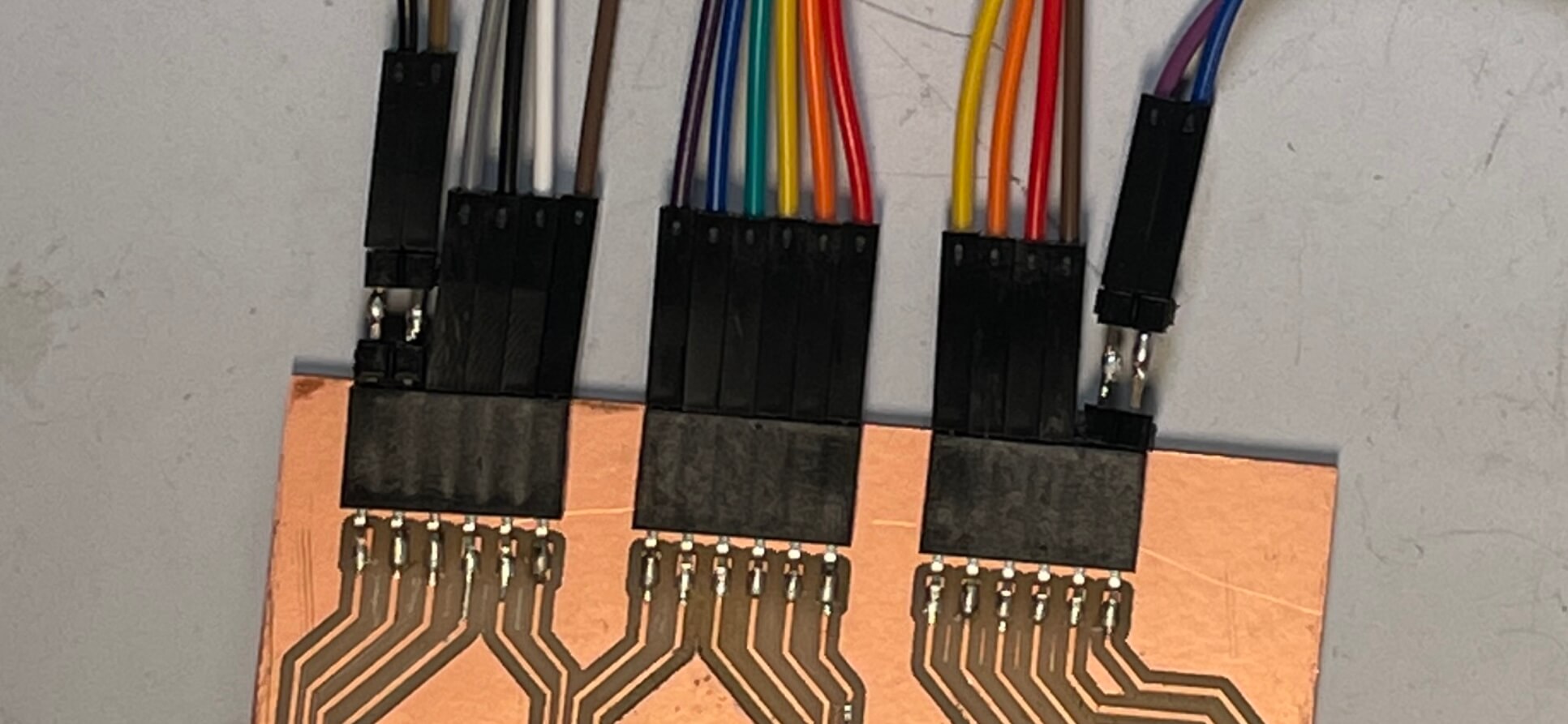
Nevermind, just solder together two male connector pins.


It turns on! But strangely, it turns on immediately once I plug it into the computer. In my head, this is not supposed to happen. The way the board is designed, power is only supposed to travel through the LEDs when the N Mosfets are tripped by a signal coming from the microcontroller pins, via the multiplexing proxy. Unless each of these multiplexer pins start in an ON position for some reason, this seems to be some kind of issue. Leo and I tried to figure it out for awhile, we tested the voltage at different parts of the board: there were 5V preceding the LED, the was a .5V drop across the MOSFET... Leo wasn't sure why the board wasn't behaving as planned. He suggested that maybe since these MOSFETs are speced for larger power applications, that there is a current leakage that is able to turn the LEDs on. We looked at the data sheet and it said it might be able to leak 10mA of current, but I wondered if this would really be enough to make the LEDs are bright as they were.
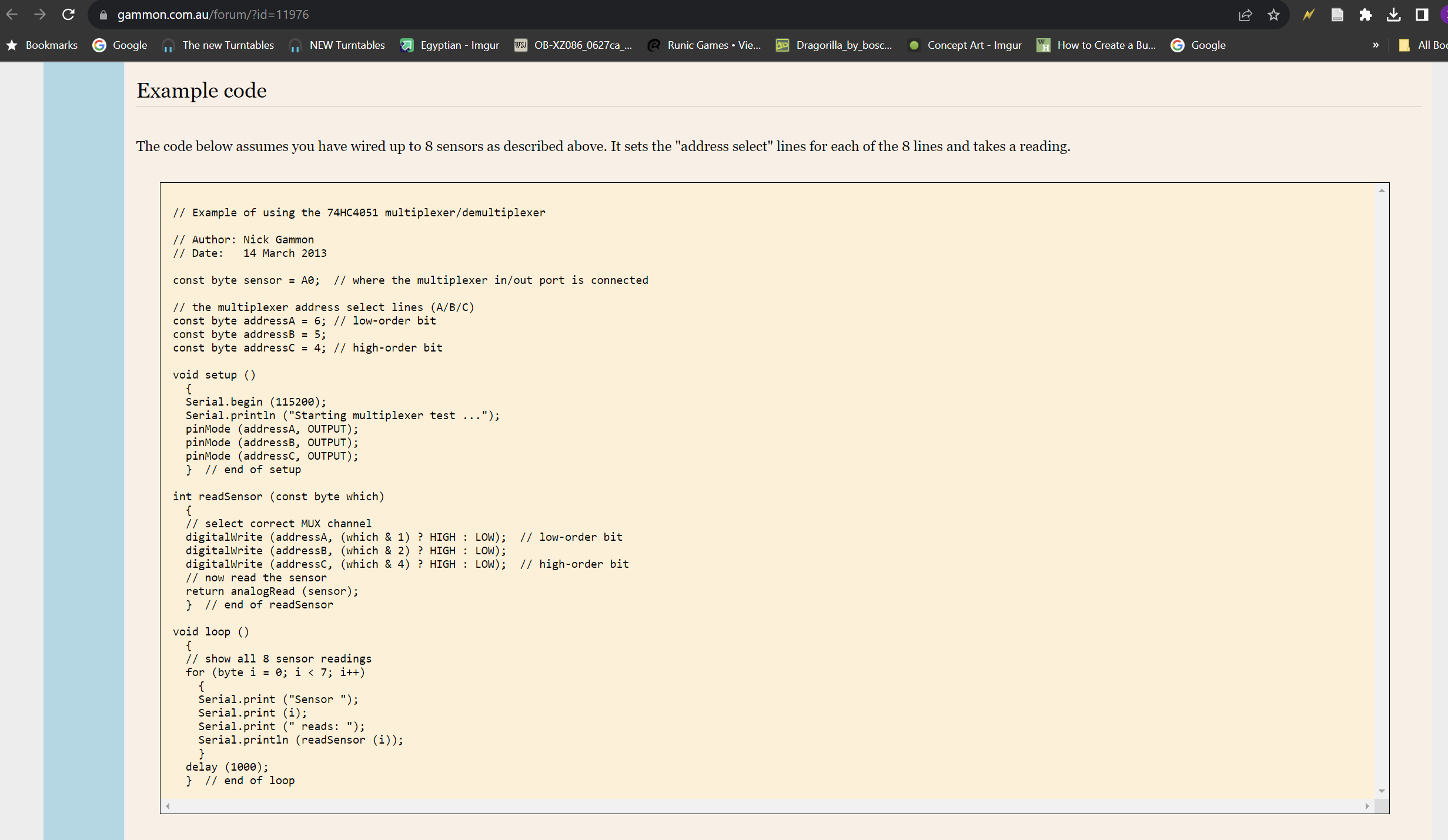
I was using this as my code
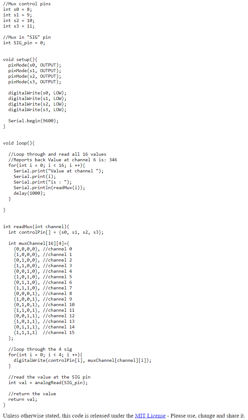
I also tried using this as my code